M35
www.vishay.com
Vishay
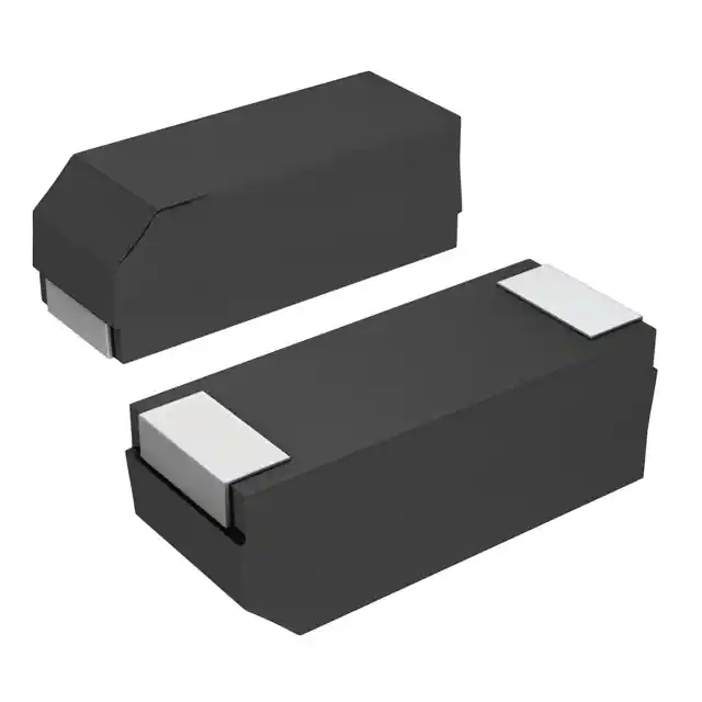
Wet Tantalum Capacitors Surface Mount, Molded Case
FEATURES
• Molded surface mountable design
• Terminations: standard tin/lead (SnPb),
100 % tin (RoHS compliant) available
• Industry standard ratings
• Model M35 wet tantalum electrolytic chip
capacitors incorporate the advantages of all the
varieties of electrolytic capacitors and eliminate most of
the disadvantages. These units have a 3 V reverse voltage
capability at + 85 °C and a higher ripple current capability
than any other electrolytic type with similar combinations
of capacitance and case size.
• Compliant to RoHS Directive 2002/95/EC
Note
* Pb containing terminations are not RoHS compliant, exemptions
may apply
PERFORMANCE CHARACTERISTICS
Life Test: Capacitors are capable of withstanding a 2000 h
life test at a temperature of + 85 °C or + 125 °C at the
applicable rated DC working voltage.
Following life test:
1. DCL, measured at + 85 °C rated voltage, shall not be in
excess of the original requirement.
2. The equivalent series resistance shall not exceed 150 %
of the initial requirement.
3. Change in capacitance shall not exceed 10 % from the
initial measurement.
Operating Temperature: - 55 °C to + 85 °C
(to + 125 °C with voltage derating)
Capacitance Tolerance: At 120 Hz, + 25 °C. ± 20 %
standard. ± 10 %, ± 5 % available as special.
DC Leakage Current (DCL Max.): At + 25 °C and above:
Leakage current shall not exceed the values listed in the
Standard Ratings Tables.
ORDERING INFORMATION
M35
C
826
M
125
B
Z
S
L
MODEL
CASE
CODE
CAPACITANCE
CAPACITANCE
TOLERANCE
DC VOLTAGE RATING
AT + 85 °C
TERMINATION
AND PACKAGING
RELIABILITY
LEVEL
TEMP
ESR
See
Ratings
and Case
Codes
table
This is
expressed in
picofarads.
The first two
digits are the
significant
figures. The
third is the
number of zeros
to follow.
K = ± 10 %
M = ± 20 %
This is expressed in
volts. To complete the
three-digit block,
zeros precede the
voltage rating.
A decimal point is
indicated by an “R”
(6R3 = 6.3 V)
A = 100 % tin
(RoHS compliant),
bulk
B = Std, tin/lead,
bulk
Z = Non-ER
S = Std
S = Std.
L = Low
Note
• Packaging: The use of formed plastic tubes for packing bulk components is standard
TH
H
TW
DIMENSIONS in inches [millimeters]
W
L
P
CASE CODE
L (MAX.)
W
H
P (MIN.)
TW
TH (MIN.)
C
0.835
[21.2]
0.315 ± 0.012
[8 ± 0.3]
0.295 ± 0.012
[7.5 ± 0.3]
0.118
[3.0]
0.236 ± 0.012
[6.0 ± 0.3]
0.075
[1.9]
Revision: 07-Nov-11
Document Number: 40095
1
For technical questions, contact: tantalum@vishay.com
THIS DOCUMENT IS SUBJECT TO CHANGE WITHOUT NOTICE. THE PRODUCTS DESCRIBED HEREIN AND THIS DOCUMENT
ARE SUBJECT TO SPECIFIC DISCLAIMERS, SET FORTH AT www.vishay.com/doc?91000
�M35
www.vishay.com
Vishay
RECOMMENDED REFLOW PROFILES
Tp °C
tp
TEMPERATURE (°C)
TL °C
Ts MAX. °C
(tL)
Ts MIN. °C
PREHEAT (ts)
25 °C
TIME (s)
ALL CASE CODES
Tp
Tp
Lead (Pb)-free Sn/Pb
260 °C
tp
TL
Ts MIN.
Ts MAX.
Ts MAX.
ts
TL
Ts MIN.
Lead (Pb)-free Sn/Pb Lead (Pb)-free Sn/Pb Lead (Pb)-free Sn/Pb Lead (Pb)-free
240 °C 10
217 °C
183 °C
150 °C
100 °C
200 °C
150 °C
60 to 150
ts
Sn/Pb
tL
60 to 90 60
MOUNTING
Due to the size and weight of these capacitors, we recommend that a supplemental mounting restraint to be used in printed
circuit board attachment in addition to the reflowed solder.
One recommendation is to use an adhesive such as defined in the J-STD-001DS.
This is the Space Application Electronic Hardware Addendum to J-STD-001 (Requirements for Solder Electrical and Electronic
Assemblies).
STANDARD RATINGS
MAX.
RIPPLE
40 kHz
+ 85 °C
RMS
- 55 °C + 85 °C + 125 °C
+ 25 °C
+ 125 °C
(mA)
MAX. DCL (μA) AT
MAX. ESR MAX. ESR
AT + 25 °C AT - 55 °C
CAPACITANCE
(μF)
CASE
CODE
PART NUMBER
30
C
M35C306(1)006(2)ZS(3)
MAX. CAPACITANCE
CHANGE (%) AT
6 VDC AT + 85 °C; 4 VDC AT + 125 °C
4.0
100
1.0
2.0
- 40
+ 10.5
+ 12
820
68
C
M35C686(1)006(2)ZS(3)
3.2
60
1.0
2.0
- 40
+ 14
+ 16
960
220
C
M35C227(1)006(2)ZS(3)
3.0
36
2.0
9.0
- 64
+ 13
+ 16
1000
25
C
M35C256(1)008(2)ZS(3)
4.0
100
1.0
2.0
- 40
+ 10.5
+ 12
820
56
C
M35C566(1)008(2)ZS(3)
3.3
59
1.0
2.0
- 40
+ 14
+ 16
900
180
C
M35C187(1)008(2)ZS(3)
3.0
45
2.0
9.0
- 60
+ 13
+ 16
1000
20
C
M35C206(1)010(2)ZS(3)
4.0
120
1.0
2.0
- 32
+ 10.5
+ 12
820
47
C
M35C476(1)010(2)ZS(3)
3.7
90
1.0
2.0
- 36
+ 14
+ 16
855
120
C
M35C127(1)010(2)ZS(3)
3.2
54
2.0
6.0
- 40
+ 14
+ 16
900
150
C
M35C157(1)010(2)ZS(3)
3.0
54
2.0
9.0
- 55
+ 13
+ 16
900
8 VDC AT + 85 °C; 5 VDC AT + 125 °C
10 VDC AT + 85 °C; 7 VDC AT + 125 °C
Note
• Part number definitions:
(1) Capacitance tolerance: K, M
(2) Termination/packaging: (see Ordering Information)
Reliability level: Z = Non-ER
Temperature: S = STD
(3) ESR: S = STD, L = Low (1/2 standard ESR value)
Revision: 07-Nov-11
Document Number: 40095
2
For technical questions, contact: tantalum@vishay.com
THIS DOCUMENT IS SUBJECT TO CHANGE WITHOUT NOTICE. THE PRODUCTS DESCRIBED HEREIN AND THIS DOCUMENT
ARE SUBJECT TO SPECIFIC DISCLAIMERS, SET FORTH AT www.vishay.com/doc?91000
�M35
www.vishay.com
Vishay
STANDARD RATINGS
MAX.
RIPPLE
40 kHz
+ 85 °C
RMS
+ 25 °C + 125 °C - 55 °C + 85 °C + 125 °C
(mA)
MAX. DCL (μA) AT
MAX. ESR MAX. ESR
AT + 25 °C AT - 55 °C
CAPACITANCE
(μF)
CASE
CODE
PART NUMBER
15
33
82
100
C
C
C
C
M35C156(1)015(2)ZS(3)
M35C336(1)015(2)ZS(3)
M35C826(1)015(2)ZS(3)
M35C107(1)015(2)ZS(3)
10
22
56
68
C
C
C
C
M35C106(1)025(2)ZS(3)
M35C226(1)025(2)ZS(3)
M35C566(1)025(2)ZS(5)
M35C686(1)025(2)ZS(5)
8
15
47
56
C
C
C
C
M35C805(1)030(2)ZS(3)
M35C156(1)030(2)ZS(3)
M35C476(1)030(2)ZS(3)
M35C566(1)030(2)ZS(3)
15
39
C
C
M35C156(1)035(2)ZS(3)
M35C396(1)035(2)ZS(3)
5
10
33
C
C
C
M35C505(1)050(2)ZS(3)
M35C106(1)050(2)ZS(3)
M35C336(1)050(2)ZS(3)
4
8.2
27
C
C
C
M35C405(1)060(2)ZS(3)
M35C825(1)060(2)ZS(3)
M35C276(1)060(2)ZS(3)
3.5
6.8
22
C
C
C
M35C355(1)075(2)ZS(3)
M35C685(1)075(2)ZS(3)
M35C226(1)075(2)ZS(3)
2.5
4.7
10
C
C
C
M35C255(1)100(2)ZS(3)
M35C475(1)100(2)ZS(3)
M35C106(1)100(2)ZS(3)
1.7
3.6
6.8
C
C
C
M35C175(1)125(2)ZS(3)
M35C365(1)125(2)ZS(3)
M35C685(1)125(2)ZS(3)
MAX. CAPACITANCE
CHANGE (%) AT
15 VDC AT + 85 °C; 10 VDC AT + 125 °C
4.4
4.0
3.9
3.9
155
90
72
72
1.0
1.0
2.0
2.0
2.0
2.0
6.0
9.0
- 24
- 28
- 35
- 44
+ 10.5
+ 14
+ 12
+ 13
+ 12
+ 16
+ 16
+ 16
780
820
900
900
2.0
2.0
6.0
9.0
- 16
- 20
- 25
- 40
+8
+ 10.5
+ 12
+ 12
+9
+ 12
+ 15
+ 15
715
800
850
850
2.0
2.0
6.0
9.0
- 16
- 20
- 23
- 38
+8
+ 10.5
+ 12
+ 12
+ 12
+ 12
+ 15
+ 15
640
780
800
800
1.5
6.0
- 20
- 22
+ 10.5
+ 12
+ 12
+ 14
660
820
2.0
2.0
9.0
- 16
- 24
- 29
+5
+8
+ 10
+6
+9
+ 12
580
715
700
2.0
2.0
12
- 16
- 24
- 24
+5
+8
+ 10
+6
+9
+ 12
525
625
700
2.0
2.0
12
- 16
- 20
- 19
+5
+8
+ 10
+6
+9
+ 12
525
610
600
2.0
2.0
12
- 16
- 16
- 17
+7
+7
+ 10
+8
+8
+ 12
505
565
800
2.0
2.0
12
- 16
- 16
- 14
+7
+7
+ 10
+8
+8
+ 12
415
520
700
25 VDC AT + 85 °C; 15 VDC AT + 125 °C
5.3
4.2
4.3
4.3
220
140
90
90
1.0
1.0
2.0
2.0
30 VDC AT + 85 °C; 20 VDC AT + 125 °C
6.6
6.2
5.2
5.2
275
175
100
100
1.0
1.0
2.0
2.0
35 VDC AT + 85 °C; 22 VDC AT + 125 °C
6.2
4.1
175
61
0.75
2.0
50 VDC AT + 85 °C; 30 VDC AT + 125 °C
8.0
6.4
5.0
400
250
135
1.0
1.0
2.0
60 VDC AT + 85 °C; 40 VDC AT + 125 °C
9.3
6.6
5.0
550
275
144
1.0
1.0
3.0
75 VDC AT + 85 °C; 50 VDC AT + 125 °C
9.5
6.8
5.1
650
300
157
1.0
1.0
3.0
100 VDC AT + 85 °C; 65 VDC AT + 125 °C
10.6
8.5
5.9
950
500
200
1.0
1.0
3.0
125 VDC AT + 85 °C; 85 VDC AT + 125 °C
15.6
10.0
11.7
1250
600
300
1.0
1.0
3.0
Note
• Part number definitions:
(1) Capacitance tolerance: K, M
(2) Termination/packaging: (see Ordering Information)
Reliability level: Z = Non-ER
Temperature: S = STD
(3) ESR: S = STD, L = Low (1/2 standard ESR value)
Revision: 07-Nov-11
Document Number: 40095
3
For technical questions, contact: tantalum@vishay.com
THIS DOCUMENT IS SUBJECT TO CHANGE WITHOUT NOTICE. THE PRODUCTS DESCRIBED HEREIN AND THIS DOCUMENT
ARE SUBJECT TO SPECIFIC DISCLAIMERS, SET FORTH AT www.vishay.com/doc?91000
�M35
www.vishay.com
Vishay
PERFORMANCE CHARACTERISTICS OF M35 CAPACITORS
ELECTRICAL CHARACTERISTICS
ITEM
Operating temperature range
Capacitor tolerance
Capacitance change (maximum)
ESR
AC ripple current
DCL (maximum leakage current)
Impedance (maximum)
PERFORMANCE CHARACTERISTICS
- 55 °C to + 125 °C
± 20 %, ± 10 % at 120 Hz
Limits per Standard Ratings table. Measured per requirements of MIL-PRF-39006.
Reverse voltage shall be in accordance with MIL-PRF-39006/22.
Units are capable of withstanding 3 V in reverse at + 85 °C for 125 h.
Surge voltage shall be in accordance with MIL-PRF-39006.
The DC rated surge voltage is the maximum voltage to which the capacitors should be subjected
under any conditions. This includes transients and peak ripple at the highest line voltage. The
surge voltage is 115 % of rated DC working voltage.
The capacitors shall be capable of withstanding a 2000 h life test at 85 °C at rated voltage.
Reverse voltage
Surge voltage
Life test
ENVIRONMENTAL CHARACTERISTICS
ITEM
Hermeticity
Moisture resistance
Altitude/barometric pressure
(reduced)
CONDITION
MIL-PRF-39006
MIL-PRF-39006
COMMENTS
The internal component has been tested to be compliant to
hermeticity requirements of MIL-PRF-39006/22.
The internal component has been tested to be compliant to
moisture resistance requirements of MIL-PRF-39006/22.
The internal component has been tested to be compliant to
altitude or reduced barometric pressure requirements
MIL-PRF-39006/22 (150 000 feet).
MIL-PRF-39006
the
the
the
of
MECHANICAL CHARACTERISTICS
ITEM
Thermal shock
Shock
Vibration (high frequency)
Vibration (random)
CONDITION
MIL-STD-202, Method 107, A
MIL-STD-202, Method 213
MIL-STD-202, Method 204
MIL-STD-202, Method 214
Resistance to solder heat
MIL-STD-202, Method 210
Solderability
ANSI J-STD-002
Part markings
MIL-STD-1285
Weight (typical) in g
3.5
COMMENTS
Per MIL-PRF-39006, 30 cycles
Per MIL-PRF-39006, 500 g
Per MIL-PRF-39006, 80 g
Per MIL-PRF-39006, 53.79 g
The capacitor must withstand solder dipping of the terminals at
260 °C for 10 s. The capacitor must not be visibly damaged and the
electrical characteristics must not be affected.
The terminations must be solderable per the requirements of
MIL-PRF-55365 para. 4.10
The part marking shall include Vishay name, trademark,
capacitance, voltage, date code and lot symbol.
PAD DIMENSIONS in millimeters
D
A
C
CASE CODE
C
A (MIN.)
22.7
B
B (NOM.)
14.7
C
C (NOM.)
4.0
D (NOM.)
6.4
STANDARD PACKAGING QUANTITY
SERIES
M35
Revision: 07-Nov-11
CASE CODE
C
BULK/TUBE
10 pcs
Document Number: 40095
4
For technical questions, contact: tantalum@vishay.com
THIS DOCUMENT IS SUBJECT TO CHANGE WITHOUT NOTICE. THE PRODUCTS DESCRIBED HEREIN AND THIS DOCUMENT
ARE SUBJECT TO SPECIFIC DISCLAIMERS, SET FORTH AT www.vishay.com/doc?91000
�Legal Disclaimer Notice
www.vishay.com
Vishay
Disclaimer
ALL PRODUCT, PRODUCT SPECIFICATIONS AND DATA ARE SUBJECT TO CHANGE WITHOUT NOTICE TO IMPROVE
RELIABILITY, FUNCTION OR DESIGN OR OTHERWISE.
Vishay Intertechnology, Inc., its affiliates, agents, and employees, and all persons acting on its or their behalf (collectively,
“Vishay”), disclaim any and all liability for any errors, inaccuracies or incompleteness contained in any datasheet or in any other
disclosure relating to any product.
Vishay makes no warranty, representation or guarantee regarding the suitability of the products for any particular purpose or
the continuing production of any product. To the maximum extent permitted by applicable law, Vishay disclaims (i) any and all
liability arising out of the application or use of any product, (ii) any and all liability, including without limitation special,
consequential or incidental damages, and (iii) any and all implied warranties, including warranties of fitness for particular
purpose, non-infringement and merchantability.
Statements regarding the suitability of products for certain types of applications are based on Vishay's knowledge of typical
requirements that are often placed on Vishay products in generic applications. Such statements are not binding statements
about the suitability of products for a particular application. It is the customer's responsibility to validate that a particular product
with the properties described in the product specification is suitable for use in a particular application. Parameters provided in
datasheets and / or specifications may vary in different applications and performance may vary over time. All operating
parameters, including typical parameters, must be validated for each customer application by the customer's technical experts.
Product specifications do not expand or otherwise modify Vishay's terms and conditions of purchase, including but not limited
to the warranty expressed therein.
Hyperlinks included in this datasheet may direct users to third-party websites. These links are provided as a convenience and
for informational purposes only. Inclusion of these hyperlinks does not constitute an endorsement or an approval by Vishay of
any of the products, services or opinions of the corporation, organization or individual associated with the third-party website.
Vishay disclaims any and all liability and bears no responsibility for the accuracy, legality or content of the third-party website
or for that of subsequent links.
Except as expressly indicated in writing, Vishay products are not designed for use in medical, life-saving, or life-sustaining
applications or for any other application in which the failure of the Vishay product could result in personal injury or death.
Customers using or selling Vishay products not expressly indicated for use in such applications do so at their own risk. Please
contact authorized Vishay personnel to obtain written terms and conditions regarding products designed for such applications.
No license, express or implied, by estoppel or otherwise, to any intellectual property rights is granted by this document or by
any conduct of Vishay. Product names and markings noted herein may be trademarks of their respective owners.
© 2022 VISHAY INTERTECHNOLOGY, INC. ALL RIGHTS RESERVED
Revision: 01-Jan-2022
1
Document Number: 91000
�