101/102 PHR-ST
www.vishay.com
Vishay BCcomponents
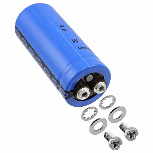
Aluminum Electrolytic Capacitors,
Power High Ripple Current, Screw Terminals
FEATURES
• Long useful life: 10 000 h to 15 000 h at +85 °C
• Low ESR
• Available in case sizes up to Ø 90 mm x 220 mm
• Polarized aluminum electrolytic capacitors,
non-solid electrolyte
• Large types, cylindrical aluminum case, insulated with a
blue sleeve
LINKS TO ADDITIONAL RESOURCES
• Pressure relief in the sealing
3D 3D
• Material categorization: for definitions of compliance
please see www.vishay.com/doc?99912
3D Models
202
PML-ST
APPLICATIONS
• Buffering and filtering
smaller size
501
PGM-ST
longer life
101/102
PHR-ST
• Motor drives, inverters, UPS, and traction systems
longer life
106
PED-ST
• Pulsed power supplies
MARKING
105 °C
The capacitors are marked with the following information:
104
PHR-ST
• Rated capacitance (in μF)
Fig. 1
• Tolerance on rated capacitance, code letter in accordance
with IEC 60062 (M for ± 20 %)
• Rated voltage (in V)
QUICK REFERENCE DATA
DESCRIPTION
VALUE
101
102
35 x 60 to 90 x 220
Nominal case size (Ø D x L in mm)
Rated capacitance range
220 μF to 1 F
(E6 series), CR
Tolerance on CR
± 20 %
25 V to 100 V 200 V to 450 V
Rated voltage range, UR
Category temperature range
-40 °C to +85 °C
Endurance test at 85 °C
2000 h
10 000 h
(D ≤ 50 mm)
10 000 h
Useful life at 85 °C
15 000 h
(D ≥ 65 mm)
400 000 h
Useful life at 40 °C,
(D ≤ 50 mm)
400 000 h
1.4 x IR applied
600 000 h
(D ≥ 65 mm)
Shelf life at 0 V, 85 °C
500 h
Based on sectional specification
IEC 60384-4 / EN 130300
Climatic category IEC 60068
40 / 085 / 056
Revision: 21-Jul-2022
• Date code
• Name of manufacturer
• Code for factory of origin
• “-” sign to identify the negative terminal, visible from the
top and side of the capacitor
• Ordering code (relevant part only)
• Climatic category in accordance with IEC 60068
Document Number: 28371
1
For technical questions, contact: aluminumcaps2@vishay.com
THIS DOCUMENT IS SUBJECT TO CHANGE WITHOUT NOTICE. THE PRODUCTS DESCRIBED HEREIN AND THIS DOCUMENT
ARE SUBJECT TO SPECIFIC DISCLAIMERS, SET FORTH AT www.vishay.com/doc?91000
�101/102 PHR-ST
www.vishay.com
Vishay BCcomponents
SELECTION CHART FOR CR, UR, AND RELEVANT NOMINAL CASE SIZES (Ø D x L in mm)
CR
(μF)
220
330
470
680
1000
1500
2200
3300
4700
5600
6800
10 000
15 000
22 000
33 000
47 000
68 000
100 000
150 000
220 000
330 000
470 000
UR (V)
25
40
63
100
200
250
350
385
400
450
-
-
-
-
-
-
-
35 x 60
35 x 60
35 x 60
-
-
-
-
-
-
35 x 60
35 x 80
35 x 60
35 x 80
-
-
-
-
-
-
-
-
35 x 80
-
-
-
-
-
-
35 x 60
35 x 80
35 x 80
35 x 80
35 x 105
-
-
-
-
-
-
-
-
35 x 105
-
-
-
-
-
35 x 60
35 x 80
35 x 105
35 x 105
35 x 105
50 x 80
-
-
-
-
-
-
-
-
50 x 80
-
-
-
-
-
35 x 80
35 x 80
50 x 80
50 x 80
50 x 80
50 x 80
-
-
-
-
35 x 105
35 x 105
-
-
50 x 105
50 x 105
-
-
-
-
35 x 105
35 x 105
50 x 80
50 x 105
50 x 105
50 x 105
-
-
-
-
50 x 80
50 x 80
50 x 105
-
-
65 x 105
-
-
-
35 x 60
50 x 80
50 x 80
50 x 105
65 x 105
65 x 105
65 x 105
-
-
-
-
-
50 x 105
65 x 105
-
-
76 x 105
-
-
-
35 x 60
50 x 80
50 x 105
65 x 105
76 x 105
65 x 105
76 x 105
-
-
-
35 x 80
50 x 105
65 x 105
-
-
76 x 105
76 x 146
-
-
35 x 60
35 x 80
65 x 105
65 x 105
76 x 105
76 x 105
76 x 105
76 x 146
-
-
-
35 x 105
-
76 x 105
76 x 146
76 x 146
76 x 146
-
-
-
-
-
-
-
-
-
-
76 x 146
-
-
35 x 60
35 x 105
65 x 105
76 x 105
76 x 146
76 x 146
76 x 146
76 x 220
-
-
35 x 80
50 x 80
76 x 105
76 x 146
-
-
-
90 x 146
-
35 x 60
35 x 80
50 x 80
76 x 105
76 x 105
76 x 220
-
76 x 220
90 x 220
-
-
35 x 105
50 x 105
76 x 146
76 x 146
90 x 146
-
-
-
35 x 60
35 x 60
35 x 105
50 x 105
76 x 146
76 x 146
90 x 220
-
-
-
-
35 x 80
50 x 80
-
-
-
-
-
-
-
35 x 60
35 x 80
50 x 80
65 x 105
76 x 220
76 x 220
-
-
-
-
-
50 x 80
50 x 105
76 x 105
90 x 146
90 x 146
-
-
-
-
35 x 80
35 x 105
50 x 105
76 x 105
90 x 220
90 x 220
-
-
-
-
50 x 80
50 x 80
65 x 105
76 x 146
-
-
-
-
-
-
35 x 105
50 x 80
65 x 105
76 x 146
-
-
-
-
-
-
50 x 80
50 x 105
76 x 105
-
-
-
-
-
-
-
50 x 80
50 x 105
76 x 105
76 x 146
-
-
-
-
-
-
50 x 105
65 x 105
76 x 146
-
-
-
-
-
-
-
50 x 105
65 x 105
76 x 146
76 x 220
-
-
-
-
-
-
65 x 105
76 x 105
-
90 x 146
-
-
-
-
-
-
65 x 105
76 x 105
76 x 146
90 x 220
-
-
-
-
-
-
76 x 105
76 x 146
-
-
-
-
-
-
-
-
65 x 105
76 x 146
76 x 220
-
-
-
-
-
-
-
76 x 105
-
90 x 146
-
-
-
-
-
-
-
76 x 146
76 x 220
90 x 220
-
-
-
-
-
-
-
-
90 x 146
-
-
-
-
-
-
-
-
76 x 220
90 x 220
-
-
-
-
-
-
-
-
90 x 146
-
-
-
-
-
-
-
-
-
680 000
76 x 220
-
-
-
-
-
-
-
-
-
1 000 000
90 x 220
-
-
-
-
-
-
-
-
-
Revision: 21-Jul-2022
Document Number: 28371
2
For technical questions, contact: aluminumcaps2@vishay.com
THIS DOCUMENT IS SUBJECT TO CHANGE WITHOUT NOTICE. THE PRODUCTS DESCRIBED HEREIN AND THIS DOCUMENT
ARE SUBJECT TO SPECIFIC DISCLAIMERS, SET FORTH AT www.vishay.com/doc?91000
�101/102 PHR-ST
www.vishay.com
Vishay BCcomponents
DIMENSIONS in millimeters AND AVAILABLE FORMS
Lt
Lt
Safety
vent
L
L
Thread M x S
Mb
lb
d1
d1
D
D
P
B
B
H
H
T
Standard M5 disc
T
Clamp mounting (ST)
Threaded stud mounting (STB)
Fig. 2A - Mechanical drawings for standard M5 disc versions.
For details refer to Table 1
Safety
vent
Lt
Thread M x S
Lt
L
Mb
L
d1
lb
d1
P
D
D
B
B
H
H
T
High current M6 disc
T
Clamp mounting (ST)
Threaded stud mounting (STB)
Fig. 2B - Mechanical drawings for high current M6 disc versions.
For details refer to Table 1
Notes
• Maximum permissible torque which may be applied to the termination screws: 2 Nm for M5; 2.5 Nm for M6
For accessories refer to document “Mounting Accessories”, see www.vishay.com/doc?28348
The capacitors are delivered with screws and washers
• High current disc with 1/4 28 UNF (US) thread is available on request
Table 1
DIMENSIONS in millimeters AND MASS
DESIGN
DRAWING
L±1
35 x 60
2A
63.3
68.7
35 x 80
2A
81.3
86.7
35 x 105
2A
103.3 108.7
50 x 80
2A
82.8
50 x 105
2A
65 x 105
2A
104.8 110.7
65 x 105 HC
2B
104.8 109.2
76 x 105
2A
105.8 111.7
76 x 105 HC
2B
105.8 110.2
76 x 146
2A
145.8 151.7
76 x 146 HC
2B
145.8 150.2
76 x 220
2A
76 x 220 HC
2B
90 x 146 HC
90 x 220 HC
M
S-0
Mb
Ib ± 0.1
MASS
(g)
7.9
M5
9.5
M8
12
75
7.9
M5
9.5
M8
12
95
11
7.9
M5
9.5
M8
12
130
4.8
11
7.9
M5
9.5
M12
16
200
4.8
11
7.9
M5
9.5
M12
16
300
4.6
11.9
7.9
M5
9.5
M12
16
480
P ± 0.3
T ± 0.2
35.3
12.8
7
4.6
11
35.3
12.8
7
4.6
11
35.3
12.8
7
4.6
88.8
51
22.2
7.1
104.8 110.8
51
22.2
7.1
65
28.5
7
65
28.5
5.5
3.5
18
13
M6
8.5
M12
16
480
76.4
31.8
7
4.6
11.7
7.9
M5
9.5
M12
16
700
76.4
31.8
5.5
3.5
18.3
13
M6
8.5
M12
16
700
76.4
31.8
7
4.6
11.7
7.9
M5
9.5
M12
16
1000
76.4
31.8
5.5
3.5
18.3
13
M6
8.5
M12
16
1000
219.8 225.7
76.4
31.8
7
4.6
11.7
7.9
M5
9.5
M12
16
1500
219.8 224.2
76.4
31.8
5.5
3.5
18.3
13
M6
8.5
M12
16
1500
2B
150.1 155.4
89.4
31.8
7.9
0
13
13
M6
10
M12
16
1300
2B
218.1 223.4
89.4
31.8
7.9
0
13
13
M6
10
M12
16
2000
Revision: 21-Jul-2022
Lt ± 1 D ± 1
H ± 0.3 B ± 0.3 d1 ± 0.1
Document Number: 28371
3
For technical questions, contact: aluminumcaps2@vishay.com
THIS DOCUMENT IS SUBJECT TO CHANGE WITHOUT NOTICE. THE PRODUCTS DESCRIBED HEREIN AND THIS DOCUMENT
ARE SUBJECT TO SPECIFIC DISCLAIMERS, SET FORTH AT www.vishay.com/doc?91000
�101/102 PHR-ST
www.vishay.com
Vishay BCcomponents
PACKAGING QUANTITIES AND DIMENSIONS in millimeters
PACKAGING QUANTITIES
(units per box)
50
50
50
25
25
16
16
12
12
12
12
12
12
8
8
DESIGN
35 x 60
35 x 80
35 x 105
50 x 80
50 x 105
65 x 105
65 x 105 HC
76 x 105
76 x 105 HC
76 x 146
76 x 146 HC
76 x 220
76 x 220 HC
90 x 146 HC
90 x 220 HC
Note
• For bolt version holds:
H cardbox box: + 10 mm
ORDERING EXAMPLE
ELECTRICAL DATA
SYMBOL
CR
IR
IL5
ESR
Z
CARDBOX DIMENSIONS
LxWxH
377 x 375 x 88
377 x 375 x 123
377 x 375 x 129
377 x 375 x 123
377 x 375 x 129
377 x 375 x 129
377 x 375 x 129
377 x 375 x 129
377 x 375 x 129
377 x 375 x 168
377 x 375 x 168
377 x 375 x 242
377 x 375 x 242
377 x 375 x 168
377 x 375 x 242
Electrolytic capacitor 101 series
DESCRIPTION
Rated capacitance at 100 Hz, tolerance ± 20 %
Rated RMS ripple current at 100 Hz, 85 °C
Max. leakage current after 5 min at UR
Max. equivalent series resistance at 100 Hz
Max. impedance at 20 kHz
10 000 μF / 40 V; ± 20 %
Nominal case size: Ø 35 mm x 60 mm;
ST version, standard M5 disc
Ordering code: MAL210117103E3
Note
• Unless otherwise specified, all electrical values in Table 2 and 3
apply at Tamb = 20 °C, P = 86 kPa to 106 kPa, RH = 45 % to 75 %
Table 2
ELECTRICAL DATA AND ORDERING INFORMATION FOR 101 SERIES
UR
(V)
CR
100 Hz
(μF)
25
15 000
22 000
33 000
33 000
47 000
47 000
68 000
68 000
100 000
100 000
150 000
150 000
220 000
220 000
330 000
470 000
470 000
680 000
1 000 000
NOMINAL
IR
ESR
Z
IL5
CASE SIZE 100 Hz
MAX. MAX.
LIFE
5 min
(1)
ØDxL
85 °C
(mA) 100 Hz 20 kHz CODE
(mm)
(mΩ)
(mΩ)
(A)
35 x 60
35 x 60
35 x 80
50 x 80
35 x 105
50 x 80
50 x 80
50 x 105
50 x 105
65 x 105
65 x 105
76 x 105
65 x 105
76 x 105
76 x 146
76 x 220
90 x 146
76 x 220
90 x 220
Revision: 21-Jul-2022
7.7
8.3
9.0
10.0
12.1
14.8
12.8
17.1
14.7
19.6
17.6
21.4
20.2
22.5
25.8
29.9
38.2
29.0
46.6
0.75
1.10
1.65
1.65
2.35
2.35
3.40
3.40
5.00
5.00
7.50
7.50
11.0
11.0
16.5
23.5
23.5
34.0
50.0
29
27
19
17
15
12
15
9
12
7
8
6
6
6
4
5
5
5
5
22
22
17
14
13
10
13
8
11
6
7
5
5
5
4
5
5
5
5
L1
L1
L1
L1
L1
L1
L1
L1
L1
L2
L2
L2
L2
L2
L2
L2
L2
L2
L2
STANDARD M5 DISC
HIGH CURRENT M6 DISC
ST
STB
ST
STB
ORDERING
ORDERING
ORDERING
ORDERING
CODE
CODE
CODE
CODE
MAL2101....... MAL2101....... MAL2101....... MAL2101.......
16153E3
56153E3
16223E3
56223E3
16333E3
56333E3
26333E3
66333E3
16473E3
56473E3
26473E3
66473E3
16683E3
56683E3
26683E3
66683E3
16104E3
56104E3
26104E3
66104E3
46104E3
86104E3
16154E3
56154E3
36154E3
76154E3
26154E3
66154E3
46154E3
86154E3
16224E3
56224E3
36224E3
76224E3
26224E3
66224E3
46224E3
86224E3
26334E3
66334E3
46334E3
86334E3
16474E3
56474E3
36474E3
76474E3
46474E3
86474E3
16684E3
56684E3
36684E3
76684E3
46105E3
86105E3
Document Number: 28371
4
For technical questions, contact: aluminumcaps2@vishay.com
THIS DOCUMENT IS SUBJECT TO CHANGE WITHOUT NOTICE. THE PRODUCTS DESCRIBED HEREIN AND THIS DOCUMENT
ARE SUBJECT TO SPECIFIC DISCLAIMERS, SET FORTH AT www.vishay.com/doc?91000
�101/102 PHR-ST
www.vishay.com
Vishay BCcomponents
ELECTRICAL DATA AND ORDERING INFORMATION FOR 101 SERIES
UR
(V)
40
63
CR
100 Hz
(μF)
NOMINAL
IR
ESR
Z
IL5
CASE SIZE 100 Hz 5 min
MAX. MAX.
LIFE
ØDxL
100 Hz 20 kHz CODE (1)
85 °C
(mA)
(mm)
(mΩ)
(mΩ)
(A)
STANDARD M5 DISC
HIGH CURRENT M6 DISC
ST
STB
ST
STB
ORDERING
ORDERING
ORDERING
ORDERING
CODE
CODE
CODE
CODE
MAL2101....... MAL2101....... MAL2101....... MAL2101.......
10 000
35 x 60
7.1
0.80
31
23
L1
17103E3
57103E3
-
-
15 000
35 x 60
7.8
1.20
28
22
L1
17153E3
57153E3
-
-
15 000
35 x 80
8.7
1.20
22
17
L1
27153E3
67153E3
-
-
22 000
35 x 80
9.4
1.76
20
17
L1
17223E3
57223E3
-
-
22 000
50 x 80
11.2
1.76
19
15
L1
27223E3
67223E3
-
-
33 000
35 x 105
11.0
2.64
15
13
L1
17333E3
57333E3
-
-
33 000
50 x 80
13.7
2.64
13
10
L1
27333E3
67333E3
-
-
47 000
50 x 80
14.6
3.76
12
10
L1
17473E3
57473E3
-
-
47 000
50 x 105
15.9
3.76
10
8
L1
27473E3
67473E3
-
-
68 000
50 x 105
16.9
5.44
9
8
L1
17683E3
57683E3
-
-
68 000
65 x 105
18.1
5.44
7
6
L2
27683E3
67683E3
47683E3
87683E3
100 000
65 x 105
19.2
8.0
7
6
L2
17104E3
57104E3
37104E3
77104E3
100 000
76 x 105
21.3
8.0
7
6
L2
27104E3
67104E3
47104E3
87104E3
150 000
76 x 105
20.5
12.0
7
6
L2
17154E3
57154E3
37154E3
77154E3
150 000
76 x 146
24.0
12.0
5
5
L2
27154E3
67154E3
47154E3
87154E3
220 000
76 x 146
24.5
17.6
5
5
L2
27224E3
67224E3
47224E3
87224E3
330 000
76 x 220
28.2
26.4
5
5
L2
17334E3
57334E3
37334E3
77334E3
330 000
90 x 146
38.6
26.4
5
5
L2
-
-
47334E3
87334E3
470 000
90 x 220
41.5
37.6
5
5
L2
-
-
47474E3
87474E3
4700
35 x 60
5.9
0.59
42
25
L1
18472E3
58472E3
-
-
6800
35 x 60
6.6
0.86
38
25
L1
18682E3
58682E3
-
-
6800
35 x 80
7.3
0.86
30
19
L1
28682E3
68682E3
-
-
10 000
35 x 80
8.1
1.26
27
19
L1
18103E3
58103E3
-
-
10 000
35 x 105
8.8
1.26
22
14
L1
28103E3
68103E3
-
-
15 000
35 x 105
9.7
1.89
19
14
L1
18153E3
58153E3
-
-
15 000
50 x 80
12.1
1.89
16
11
L1
28153E3
68153E3
-
-
22 000
50 x 80
11.1
2.77
19
15
L1
18223E3
58223E3
-
-
22 000
50 x 105
14.3
2.77
12
9
L1
28223E3
68223E3
-
-
33 000
50 x 105
12.9
4.16
14
12
L1
18333E3
58333E3
-
-
33 000
65 x 105
16.5
4.16
9
6
L2
28333E3
68333E3
48333E3
88333E3
47 000
65 x 105
15.6
5.92
10
8
L2
18473E3
58473E3
38473E3
78473E3
47 000
76 x 105
18.6
5.92
8
6
L2
28473E3
68473E3
48473E3
88473E3
68 000
76 x 105
20.0
8.57
7
6
L2
18683E3
58683E3
38683E3
78683E3
68 000
76 x 146
21.9
8.57
6
5
L2
28683E3
68683E3
48683E3
88683E3
100 000
76 x 146
23.4
12.6
5
5
L2
28104E3
68104E3
48104E3
88104E3
150 000
76 x 146
22.2
18.9
6
5
L2
18154E3
58154E3
38154E3
78154E3
220 000
76 x 220
27.0
27.7
5
5
L2
18224E3
58224E3
38224E3
78224E3
220 000
90 x 146
36.5
27.7
5
5
L2
-
-
48224E3
88224E3
330 000
90 x 220
42.9
41.6
5
5
L2
-
-
48334E3
88334E3
Revision: 21-Jul-2022
Document Number: 28371
5
For technical questions, contact: aluminumcaps2@vishay.com
THIS DOCUMENT IS SUBJECT TO CHANGE WITHOUT NOTICE. THE PRODUCTS DESCRIBED HEREIN AND THIS DOCUMENT
ARE SUBJECT TO SPECIFIC DISCLAIMERS, SET FORTH AT www.vishay.com/doc?91000
�101/102 PHR-ST
www.vishay.com
Vishay BCcomponents
ELECTRICAL DATA AND ORDERING INFORMATION FOR 101 SERIES
CR
100 Hz
(μF)
UR
(V)
NOMINAL
IR
ESR
Z
IL5
CASE SIZE 100 Hz 5 min
MAX. MAX.
LIFE
ØDxL
100 Hz 20 kHz CODE (1)
85 °C
(mA)
(mm)
(mΩ)
(mΩ)
(A)
STANDARD M5 DISC
HIGH CURRENT M6 DISC
ST
STB
ST
STB
ORDERING
ORDERING
ORDERING
ORDERING
CODE
CODE
CODE
CODE
MAL2101....... MAL2101....... MAL2101....... MAL2101.......
2200
35 x 60
5.2
0.44
50
29
L1
19222E3
59222E3
-
-
3300
35 x 60
6.0
0.66
42
27
L1
19332E3
59332E3
-
-
3300
35 x 80
6.6
0.66
35
21
L1
29332E3
69332E3
-
-
4700
35 x 80
7.3
0.94
31
20
L1
19472E3
59472E3
-
-
4700
35 x 105
7.9
0.94
26
16
L1
29472E3
69472E3
-
-
6800
35 x 105
8.8
1.36
23
15
L1
19682E3
59682E3
-
-
6800
50 x 80
10.9
1.36
19
12
L1
29682E3
69682E3
-
-
10 000
50 x 80
10.5
2.00
21
15
L1
19103E3
59103E3
-
-
10 000
50 x 105
13.1
2.00
14
9
L1
29103E3
69103E3
-
-
15 000
50 x 105
12.3
3.00
16
12
L1
19153E3
59153E3
-
-
22 000
65 x 105
14.8
4.40
11
8
L2
19223E3
59223E3
39223E3
79223E3
22 000
76 x 105
17.4
4.40
9
6
L2
29223E3
69223E3
49223E3
89223E3
33 000
76 x 105
19.0
6.60
8
6
L2
19333E3
59333E3
39333E3
79333E3
33 000
76 x 146
20.7
6.60
7
5
L2
29333E3
69333E3
49333E3
89333E3
47 000
76 x 146
22.4
9.40
6
5
L2
29473E3
69473E3
49473E3
89473E3
68 000
76 x 146
25.6
13.6
6
5
L2
19683E3
59683E3
39683E3
79683E3
100 000
76 x 220
31.2
20.0
5
5
L2
19104E3
59104E3
39104E3
79104E3
100 000
90 x 146
41.5
20.0
5
5
L2
-
-
49104E3
89104E3
150 000
90 x 220
49.1
30.0
5
5
L2
-
-
49154E3
89154E3
100
Note
(1) Determines the applicable row in the table “Endurance Test Duration and Useful Life”
Table 3
ELECTRICAL DATA AND ORDERING INFORMATION FOR 102 SERIES
UR
(V)
200
CR
100 Hz
(μF)
IR
Z
NOMINAL
ESR
IL5
LIFE
CASE SIZE 100 Hz
MAX. MAX.
5 min
85 °C
ØDxL
100 Hz 20 kHz CODE (1)
(mA)
(mΩ)
(A)
(mm)
(mΩ)
STANDARD M5 DISC
HIGH CURRENT M6 DISC
STB
ST
STB
ST
ORDERING
ORDERING
ORDERING
ORDERING
CODE
CODE
CODE
CODE
MAL2102....... MAL2102....... MAL2102....... MAL2102.......
680
35 x 60
3.5
0.27
207
136
L1
12681E3
52681E3
-
-
1000
35 x 80
4.4
0.40
144
95
L1
12102E3
52102E3
-
-
1000
35 x 105
4.7
0.40
140
91
L1
22102E3
62102E3
-
-
1500
35 x 105
5.5
0.60
100
67
L1
12152E3
52152E3
-
-
1500
50 x 80
6.2
0.60
106
74
L1
22152E3
62152E3
-
-
2200
50 x 80
8.0
0.88
67
44
L1
12222E3
52222E3
-
-
3300
50 x 80
8.9
1.32
50
35
L1
12332E3
52332E3
-
-
3300
50 x 105
9.9
1.32
46
32
L1
22332E3
62332E3
-
-
4700
65 x 105
12.5
1.88
37
26
L1
22472E3
62472E3
42472E3
82472E3
6800
65 x 105
15.2
2.72
25
18
L1
12682E3
52682E3
32682E3
72682E3
6800
76 x 105
16.9
2.72
25
18
L1
22682E3
62682E3
42682E3
82682E3
10 000
76 x 105
19.9
4.00
18
13
L1
12103E3
52103E3
32103E3
72103E3
10 000
76 x 146
20.4
4.00
18
13
L1
22103E3
62103E3
42103E3
82103E3
15 000
76 x 146
24.1
6.00
12
9
L1
12153E3
52153E3
32153E3
72153E3
22 000
76 x 220
29.5
8.8
9
7
L1
12223E3
52223E3
32223E3
72223E3
22 000
90 x 146
34.1
8.8
8
6
L1
-
-
42223E3
82223E3
33 000
90 x 220
41.7
13.2
6
5
L1
-
-
42333E3
82333E3
Revision: 21-Jul-2022
Document Number: 28371
6
For technical questions, contact: aluminumcaps2@vishay.com
THIS DOCUMENT IS SUBJECT TO CHANGE WITHOUT NOTICE. THE PRODUCTS DESCRIBED HEREIN AND THIS DOCUMENT
ARE SUBJECT TO SPECIFIC DISCLAIMERS, SET FORTH AT www.vishay.com/doc?91000
�101/102 PHR-ST
www.vishay.com
Vishay BCcomponents
ELECTRICAL DATA AND ORDERING INFORMATION FOR 102 SERIES
UR
(V)
250
350
385
CR
100 Hz
(μF)
IR
Z
NOMINAL
ESR
IL5
LIFE
CASE SIZE 100 Hz
MAX. MAX.
5 min
85 °C
ØDxL
100 Hz 20 kHz CODE (1)
(mA)
(mΩ)
(A)
(mm)
(mΩ)
STANDARD M5 DISC
HIGH CURRENT M6 DISC
STB
ST
STB
ST
ORDERING
ORDERING
ORDERING
ORDERING
CODE
CODE
CODE
CODE
MAL2102....... MAL2102....... MAL2102....... MAL2102.......
470
35 x 60
3.1
0.24
250
152
L1
13471E3
53471E3
-
-
680
35 x 80
3.8
0.34
175
107
L1
13681E3
53681E3
-
-
1000
35 x 80
4.4
0.50
128
82
L1
13102E3
53102E3
-
-
1000
35 x 105
4.8
0.50
122
76
L1
23102E3
63102E3
-
-
1500
35 x 105
5.4
0.75
90
58
L1
13152E3
53152E3
-
-
1500
50 x 80
7.0
0.75
81
50
L1
23152E3
63152E3
-
-
2200
50 x 80
8.0
1.10
60
39
L1
13222E3
53222E3
-
-
2200
50 x 105
8.7
1.10
57
35
L1
23222E3
63222E3
-
-
3300
50 x 105
9.8
1.65
42
28
L1
13332E3
53332E3
-
-
3300
65 x 105
11.4
1.65
42
28
L1
23332E3
63332E3
43332E3
83332E3
4700
65 x 105
13.8
2.35
29
19
L1
13472E3
53472E3
33472E3
73472E3
4700
76 x 105
15.3
2.35
29
19
L1
23472E3
63472E3
43472E3
83472E3
6800
76 x 105
18.1
3.40
21
14
L1
13682E3
53682E3
33682E3
73682E3
6800
76 x 146
18.6
3.40
21
14
L1
23682E3
63682E3
43682E3
83682E3
10 000
76 x 105
19.3
5.00
17
12
L1
13103E3
53103E3
33103E3
73103E3
10 000
76 x 146
22.0
5.00
15
10
L1
23103E3
63103E3
43103E3
83103E3
15 000
76 x 146
23.3
7.5
12
10
L1
13153E3
53153E3
33153E3
73153E3
22 000
76 x 220
29.1
11.0
9
7
L1
13223E3
53223E3
33223E3
73223E3
22 000
90 x 146
35.3
11.0
7
5
L1
-
-
43223E3
83223E3
33 000
90 x 220
43.2
16.5
5
5
L1
-
-
43333E3
83333E3
330
35 x 60
2.5
0.23
435
305
L1
15331E3
55331E3
-
-
470
35 x 80
3.1
0.33
308
216
L1
25471E3
65471E3
-
-
680
35 x 105
3.8
0.48
216
152
L1
25681E3
65681E3
-
-
1000
50 x 80
5.6
0.70
145
102
L1
25102E3
65102E3
-
-
1500
50 x 80
6.5
1.05
102
74
L1
15152E3
55152E3
-
-
1500
50 x 105
7.0
1.05
99
70
L1
25152E3
65152E3
-
-
2200
50 x 105
8.0
1.54
72
52
L1
15222E3
55222E3
-
-
2200
65 x 105
9.3
1.54
72
52
L1
25222E3
65222E3
45222E3
85222E3
3300
65 x 105
11.4
2.31
48
35
L1
25332E3
65332E3
45332E3
85332E3
4700
76 x 105
15.0
3.29
34
25
L1
15472E3
55472E3
35472E3
75472E3
4700
76 x 146
15.4
3.29
34
25
L1
25472E3
65472E3
45472E3
85472E3
6800
76 x 146
18.3
4.76
24
18
L1
25682E3
65682E3
45682E3
85682E3
10 000
76 x 220
23.2
7.0
15
12
L1
15103E3
55103E3
35103E3
75103E3
10 000
90 x 146
25.1
7.0
15
12
L1
-
-
45103E3
85103E3
15 000
90 x 220
31.2
10.5
10
8
L1
-
-
45153E3
85153E3
220
35 x 60
2.1
0.17
575
380
L1
18221E3
58221E3
-
-
330
35 x 80
2.7
0.26
386
257
L1
18331E3
58331E3
-
-
470
35 x 80
3.1
0.37
279
188
L1
18471E3
58471E3
-
-
680
35 x 105
3.9
0.53
196
133
L1
18681E3
58681E3
-
-
1000
50 x 80
5.6
0.77
132
89
L1
18102E3
58102E3
-
-
1500
50 x 105
7.1
1.16
90
61
L1
18152E3
58152E3
-
-
2200
65 x 105
10.0
1.70
61
42
L1
18222E3
58222E3
38222E3
78222E3
3300
76 x 105
13.4
2.55
42
29
L1
18332E3
58332E3
38332E3
78332E3
4700
76 x 105
15.0
3.62
31
22
L1
18472E3
58472E3
38472E3
78472E3
4700
76 x 146
16.3
3.62
29
20
L1
28472E3
68472E3
48472E3
88472E3
6800
76 x 146
18.3
5.24
22
16
L1
18682E3
58682E3
38682E3
78682E3
Revision: 21-Jul-2022
Document Number: 28371
7
For technical questions, contact: aluminumcaps2@vishay.com
THIS DOCUMENT IS SUBJECT TO CHANGE WITHOUT NOTICE. THE PRODUCTS DESCRIBED HEREIN AND THIS DOCUMENT
ARE SUBJECT TO SPECIFIC DISCLAIMERS, SET FORTH AT www.vishay.com/doc?91000
�101/102 PHR-ST
www.vishay.com
Vishay BCcomponents
ELECTRICAL DATA AND ORDERING INFORMATION FOR 102 SERIES
UR
(V)
400
450
CR
100 Hz
(μF)
220
330
330
470
470
680
680
1000
1000
1500
2200
3300
3300
4700
4700
6800
10000
220
330
470
680
1000
1000
1500
1500
2200
2200
3300
3300
4700
5600
6800
6800
10 000
IR
Z
NOMINAL
ESR
IL5
LIFE
CASE SIZE 100 Hz
MAX. MAX.
5 min
85 °C
ØDxL
100 Hz 20 kHz CODE (1)
(mA)
(mΩ)
(A)
(mm)
(mΩ)
35 x 60
35 x 60
35 x 80
35 x 80
35 x 105
35 x 105
50 x 80
50 x 80
50 x 105
50 x 105
65 x 105
65 x 105
76 x 105
76 x 105
76 x 146
76 x 146
76 x 220
35 x 60
35 x 80
35 x 105
50 x 80
50 x 80
50 x 105
50 x 105
65 x 105
65 x 105
76 x 105
76 x 105
76 x 146
76 x 146
76 x 146
76 x 220
90 x 146
90 x 220
2.1
2.5
2.7
3.1
3.3
3.9
4.5
5.7
6.0
7.1
10.0
12.1
13.4
15.0
16.4
18.3
22.1
2.1
2.7
3.4
4.9
5.7
6.1
7.1
8.3
10.1
11.2
13.5
13.9
16.4
17.3
19.8
21.3
26.5
0.18
0.26
0.26
0.38
0.38
0.55
0.54
0.80
0.80
1.20
1.76
2.64
2.64
3.76
3.76
5.44
8.0
0.20
0.30
0.42
0.61
0.90
0.90
1.35
1.35
1.98
1.98
2.97
2.97
4.23
5.04
6.1
6.1
9.0
557
383
374
271
265
191
199
128
125
88
60
40
40
31
28
22
14
503
339
241
159
118
114
81
81
55
55
37
37
26
23
25
24
17
363
254
245
180
175
128
136
86
83
59
40
27
27
21
19
15
11
313
212
151
98
75
72
52
52
35
35
24
24
17
15
20
19
14
L1
L1
L1
L1
L1
L1
L1
L1
L1
L1
L1
L1
L1
L1
L1
L1
L1
L1
L1
L1
L1
L1
L1
L1
L1
L1
L1
L1
L1
L1
L1
L1
L1
L1
STANDARD M5 DISC
HIGH CURRENT M6 DISC
STB
ST
STB
ST
ORDERING
ORDERING
ORDERING
ORDERING
CODE
CODE
CODE
CODE
MAL2102....... MAL2102....... MAL2102....... MAL2102.......
16221E3
56221E3
16331E3
56331E3
26331E3
66331E3
16471E3
56471E3
26471E3
66471E3
16681E3
56681E3
26681E3
66681E3
16102E3
56102E3
26102E3
66102E3
26152E3
66152E3
26222E3
66222E3
46222E3
86222E3
16332E3
56332E3
36332E3
76332E3
26332E3
66332E3
46332E3
86332E3
16472E3
56472E3
36472E3
76472E3
26472E3
66472E3
46472E3
86472E3
26682E3
66682E3
46682E3
86682E3
16103E3
56103E3
36103E3
76103E3
17221E3
57221E3
27331E3
67331E3
27471E3
67471E3
27681E3
67681E3
17102E3
57102E3
27102E3
67102E3
17152E3
57152E3
27152E3
67152E3
47152E3
87152E3
17222E3
57222E3
37222E3
77222E3
27222E3
67222E3
47222E3
87222E3
17332E3
57332E3
37332E3
77332E3
27332E3
67332E3
47332E3
87332E3
17472E3
57472E3
37472E3
77472E3
17562E3
57562E3
37562E3
77562E3
17682E3
57682E3
37682E3
77682E3
47682E3
87682E3
47103E3
87103E3
Note
(1) Determines the applicable row in the table “Endurance Test Duration and Useful Life”
ADDITIONAL ELECTRICAL DATA
PARAMETER
Voltage
Surge voltage
CONDITIONS
VALUE
≤ 250 V versions
≥ 350 V versions
US = 1.15 x UR
US = 1.1 x UR
Urev ≤ 1 V
After 1 min at UR
After 5 min at UR
IL1 ≤ 0.006 CR x UR
IL5 ≤ 0.002 CR x UR
Case Ø D = 35 mm
Case Ø D = 50 mm
Case Ø D = 65 mm
Case Ø D = 76 mm
Case Ø D = 90 mm
Typ. 13 nH
Typ. 16 nH
Typ. 19 nH (1)
Typ. 20 nH (1)
Typ. 21 nH (1)
Reverse voltage
Current
Leakage current
Inductance
Equivalent series inductance (ESL)
Note
(1) Low ESL designs available on request
Revision: 21-Jul-2022
Document Number: 28371
8
For technical questions, contact: aluminumcaps2@vishay.com
THIS DOCUMENT IS SUBJECT TO CHANGE WITHOUT NOTICE. THE PRODUCTS DESCRIBED HEREIN AND THIS DOCUMENT
ARE SUBJECT TO SPECIFIC DISCLAIMERS, SET FORTH AT www.vishay.com/doc?91000
�101/102 PHR-ST
www.vishay.com
Vishay BCcomponents
RIPPLE CURRENT AND USEFUL LIFE
1.5
1.4
1.3
IR Forced
IR Free
1.2
1.1
1
0
1
0.5
1.5
2.5
2
3
3.5
4
4.5
5
Air Velocity (m/s)
Fig. 3 - Multiplier of ripple current (IR) as a function of air flow
MAXIMUM RIPPLE CURRENT
PARAMETER
Ambient temperature (Tamb)
Operating frequency (f)
Air flow
CONDITION
MAXIMUM RIPPLE CURRENT MULTIPLIER
VALUE
70 °C
From nomogram; see Fig. 4
1.6
400 Hz
From frequency; see Table 4
1.3
2 m/s
From air flow; see Fig. 3
1.25
Note
• Calculation example for 102 series. Maximum ripple current multiplier = 1.6 x 1.3 x 1.25 = 2.6
Table 4
ENDURANCE TEST DURATION AND USEFUL LIFE
LIFE CODE
ENDURANCE AT 85 °C
(h)
USEFUL LIFE AT 85 °C
(h)
L1
2000
10 000
L2
2000
15 000
Note
• Multiplier of useful life code: CCC205-05
Revision: 21-Jul-2022
Document Number: 28371
9
For technical questions, contact: aluminumcaps2@vishay.com
THIS DOCUMENT IS SUBJECT TO CHANGE WITHOUT NOTICE. THE PRODUCTS DESCRIBED HEREIN AND THIS DOCUMENT
ARE SUBJECT TO SPECIFIC DISCLAIMERS, SET FORTH AT www.vishay.com/doc?91000
�101/102 PHR-ST
www.vishay.com
Vishay BCcomponents
CCC205-05
2.6
IA
IR
2.4
2.2
2.0
1.8
1.6
1.4
lifetime multiplier
1.2
(1)
0.8
1.0
1.5
2.0
3.0
4.0
6.0
10
20
Useful life at 85 °C and IR applied:
101 series: case Ø ≤ 50: 10 000 h
case Ø ≥ 65: 15 000 h
102 series: 10 000 h
30
(1)
40
IA = Actual ripple current at 100 Hz
IR = Rated ripple current at 100 Hz and 85 °C 1.0
0.5
0.0
40
50
60
70
80
90
100
Tamb (°C)
Fig. 4 - Multiplier of useful life as a function of ambient temperature and ripple current load
Table 5
MULTIPLIER OF RIPPLE CURRENT (IR) AS A FUNCTION OF FREQUENCY
FREQUENCY (Hz)
UR
(V)
50
100
200
400
1000
10 000
IR MULTIPLIER
25
0.85
1.00
1.10
1.15
1.20
1.30
40
0.85
1.00
1.10
1.15
1.20
1.30
63
0.85
1.00
1.10
1.15
1.20
1.30
100
0.85
1.00
1.10
1.15
1.20
1.30
200
0.90
1.00
1.20
1.30
1.40
1.50
250
0.90
1.00
1.20
1.30
1.40
1.50
350
0.90
1.00
1.20
1.30
1.40
1.50
385
0.90
1.00
1.20
1.30
1.40
1.50
400
0.90
1.00
1.20
1.30
1.40
1.50
450
0.90
1.00
1.20
1.30
1.40
1.50
Revision: 21-Jul-2022
Document Number: 28371
10
For technical questions, contact: aluminumcaps2@vishay.com
THIS DOCUMENT IS SUBJECT TO CHANGE WITHOUT NOTICE. THE PRODUCTS DESCRIBED HEREIN AND THIS DOCUMENT
ARE SUBJECT TO SPECIFIC DISCLAIMERS, SET FORTH AT www.vishay.com/doc?91000
�101/102 PHR-ST
www.vishay.com
Vishay BCcomponents
Table 6
TEST PROCEDURES AND REQUIREMENTS
TEST
NAME OF TEST
Endurance
PROCEDURE
(quick reference)
REFERENCE
IEC 60384-4 /
EN 130300
subclause 4.13
Tamb = 85 °C; UR applied;
2000 h
Tamb = 85 °C; UR and IR applied
Useful life
CECC 30301
subclause 1.8.1
101 series:
case Ø D ≤ 50: 10 000 h
case Ø D ≥ 65: 15 000 h
102 series:
10 000 h
Shelf life
(storage at
high temperature)
IEC 60384-4 /
EN 130300
subclause 4.17
Tamb = 85 °C; no voltage applied;
500 h
After test: UR to be applied for 30 min,
24 h to 48 h before measurement
REQUIREMENTS
UR ≤ 100 V; ΔC/C: ± 15 %
UR > 100 V; ΔC/C: ± 10 %
tan δ ≤ 1.3 x spec. limit
Z ≤ 2 x spec. limit
IL5 ≤ spec. limit
UR ≤ 100 V; ΔC/C: ± 45 %
UR > 100 V; ΔC/C: ± 30 %
tan δ ≤ 3 x spec. limit
Z ≤ 3 x spec. limit
IL5 ≤ spec. limit
no short or open circuit,
no visible damage
Total failure percentage:
UR ≤ 100 V; ≤ 1 %
UR > 100 V; ≤ 3 %
ΔC/C: ± 10 %
tan δ ≤ 1.2 x spec. limit
IL5 ≤ 2 x spec. limit
Statements about product lifetime are based on calculations and internal testing. They should only be interpreted as estimations. Also due to external factors, the
lifetime in the field application may deviate from the calculated lifetime. In general, nothing stated herein shall be construed as a guarantee of durability.
Revision: 21-Jul-2022
Document Number: 28371
11
For technical questions, contact: aluminumcaps2@vishay.com
THIS DOCUMENT IS SUBJECT TO CHANGE WITHOUT NOTICE. THE PRODUCTS DESCRIBED HEREIN AND THIS DOCUMENT
ARE SUBJECT TO SPECIFIC DISCLAIMERS, SET FORTH AT www.vishay.com/doc?91000
�Legal Disclaimer Notice
www.vishay.com
Vishay
Disclaimer
ALL PRODUCT, PRODUCT SPECIFICATIONS AND DATA ARE SUBJECT TO CHANGE WITHOUT NOTICE TO IMPROVE
RELIABILITY, FUNCTION OR DESIGN OR OTHERWISE.
Vishay Intertechnology, Inc., its affiliates, agents, and employees, and all persons acting on its or their behalf (collectively,
“Vishay”), disclaim any and all liability for any errors, inaccuracies or incompleteness contained in any datasheet or in any other
disclosure relating to any product.
Vishay makes no warranty, representation or guarantee regarding the suitability of the products for any particular purpose or
the continuing production of any product. To the maximum extent permitted by applicable law, Vishay disclaims (i) any and all
liability arising out of the application or use of any product, (ii) any and all liability, including without limitation special,
consequential or incidental damages, and (iii) any and all implied warranties, including warranties of fitness for particular
purpose, non-infringement and merchantability.
Statements regarding the suitability of products for certain types of applications are based on Vishay's knowledge of typical
requirements that are often placed on Vishay products in generic applications. Such statements are not binding statements
about the suitability of products for a particular application. It is the customer's responsibility to validate that a particular product
with the properties described in the product specification is suitable for use in a particular application. Parameters provided in
datasheets and / or specifications may vary in different applications and performance may vary over time. All operating
parameters, including typical parameters, must be validated for each customer application by the customer's technical experts.
Product specifications do not expand or otherwise modify Vishay's terms and conditions of purchase, including but not limited
to the warranty expressed therein.
Hyperlinks included in this datasheet may direct users to third-party websites. These links are provided as a convenience and
for informational purposes only. Inclusion of these hyperlinks does not constitute an endorsement or an approval by Vishay of
any of the products, services or opinions of the corporation, organization or individual associated with the third-party website.
Vishay disclaims any and all liability and bears no responsibility for the accuracy, legality or content of the third-party website
or for that of subsequent links.
Except as expressly indicated in writing, Vishay products are not designed for use in medical, life-saving, or life-sustaining
applications or for any other application in which the failure of the Vishay product could result in personal injury or death.
Customers using or selling Vishay products not expressly indicated for use in such applications do so at their own risk. Please
contact authorized Vishay personnel to obtain written terms and conditions regarding products designed for such applications.
No license, express or implied, by estoppel or otherwise, to any intellectual property rights is granted by this document or by
any conduct of Vishay. Product names and markings noted herein may be trademarks of their respective owners.
© 2023 VISHAY INTERTECHNOLOGY, INC. ALL RIGHTS RESERVED
Revision: 01-Jan-2023
1
Document Number: 91000
�