MPM (Divider)
www.vishay.com
Vishay Dale Thin Film
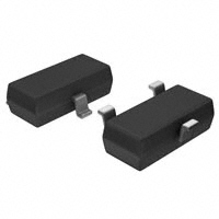
Molded, SOT-23 Thin Film Resistor, Surface Mount Divider Network
FEATURES
• Excellent long term ratio stability
(ΔR ± 0.015 %, 2000 h, +70 °C)
• Ratio tolerances to ± 0.01 %
Available
• Low TCR tracking ± 2 ppm
• Zero ohm jumper option available
• Standard JEDEC® TO-236 package variation AB
• Material categorization: for definitions of compliance
please see www.vishay.com/doc?99912
Note
* This datasheet provides information about parts that are
RoHS-compliant and / or parts that are non RoHS-compliant. For
example, parts with lead (Pb) terminations are not RoHS-compliant.
Please see the information / tables in this datasheet for details
LINKS TO ADDITIONAL RESOURCES
Footprints
Packages
TYPICAL PERFORMANCE
Vishay Dale Thin Film MPM Series Dividers provide
± 2 ppm/°C tracking and a ratio tolerance as tight as 0.01 %,
small size, and exceptional stability for all surface mount
applications. The standard SOT-23 package format with
unity and common standard resistance divider ratios
provide easy selection for most applications requiring
matched pair resistor elements. The ratios listed are
available for off the shelf delivery. Ratios not listed but within
the datasheet limits are available without NRE charge. See
“Global Part Number Information” table for guidance how to
create part number for ordering.
ABSOLUTE
TCR
TOL.
TRACKING
25
2
ABSOLUTE
RATIO
0.1
0.05
Note
• Typical performance TCR and tolerance does not apply to zero
ohm jumper
SCHEMATIC
3
R1
1
R2
2
STANDARD DIVIDER RATIOS (R2/R1) COMMONLY STOCKED BY DISTRIBUTORS
RATIO
100:1
50:1
25:1
20:1
10:1
10:1
9:1
9:1
6:1
5:1
5:1
4:1
4:1
3:1
2:1
2:1
Revision: 03-Jan-2022
R2 (Ω)
100K
50K
25K
20K
20K
10K
9K
900
6K
10K
5K
8K
4K
7.5K
50K
12K
R1 (Ω)
1K
1K
1K
1K
2K
1K
1K
100
1K
2K
1K
2K
1K
2.5K
25K
6K
RATIO
2:1
2:1
1:1
1:1
1:1
1:1
1:1
1:1
1:1
1:1
1:1
1:1
1:2
1:2.5
1:4
1:9
R2 (Ω)
10K
2K
100K
50K
25K
10K
5K
2.5K
2K
1K
500
250
5K
10K
7.5K
10K
R1 (Ω)
5K
1K
100K
50K
25K
10K
5K
2.5K
2K
1K
500
250
10K
25K
30K
90K
Document Number: 60001
1
For technical questions, contact: thinfilm@vishay.com
THIS DOCUMENT IS SUBJECT TO CHANGE WITHOUT NOTICE. THE PRODUCTS DESCRIBED HEREIN AND THIS DOCUMENT
ARE SUBJECT TO SPECIFIC DISCLAIMERS, SET FORTH AT www.vishay.com/doc?91000
�MPM (Divider)
www.vishay.com
Vishay Dale Thin Film
STANDARD ELECTRICAL SPECIFICATIONS
TEST
Material
Pin/Lead Number
Resistance Range
Resistance for Jumper
TCR: Absolute
TCR: Tracking
Tolerance: Absolute
Tolerance: Ratio
Power Rating: Resistor
Power Rating: Package
Stability: Absolute
Stability: Ratio
Voltage Coefficient
Working Voltage
Operating Temperature Range
Storage Temperature Range
Noise
Thermal EMF
Shelf Life Stability: Absolute
Shelf Life Stability: Ratio
SPECIFICATIONS
Passivated nichrome
3
250 Ω to 100 kΩ per resistor
≤ 50 mΩ
± 25 ppm/°C
± 2 ppm/°C (typical)
± 0.05 % to ± 1.0 %
± 0.01 % to 0.5 %
100 mW
200 mW
ΔR ± 0.05 %
ΔR ± 0.015 %
0.1 ppm/V
100 V max. not to exceed P x R
-55 °C to +125 °C
-55 °C to +150 °C
< -30 dB
0.2 μV/°C
ΔR ± 0.01 %
ΔR ± 0.002 %
CONDITIONS
-55 °C to +125 °C
-55 °C to +125 °C
+25 °C
+25 °C
Maximum at +70 °C
Maximum at +70 °C
2000 h at +70 °C
2000 h at +70 °C
1 year at +25 °C
1 year at +25 °C
Note
• TCR and TCR tracking are not available for parts with zero ohm jumpers
DIMENSIONS AND IMPRINTING in inches and millimeters
INCHES
MIN.
MAX.
0.031
0.040
0.001
0.004
0.105
0.120
0.071
0.079
0.015
0.021
0.083
0.098
0.047
0.055
0.005
0.010
0.0035
0.0059
0.017
0.022
0
8°
DIMENSION
T
H L
A
S
A1
K
1
Pin #
2
J
MECHANICAL SPECIFICATIONS
Resistive Element
Substrate Material
Body
Terminals
Lead (Pb)-free Option
Tin Lead Option
Tin Lead and Lead (Pb)-free Finish
Passivated nichrome
Silicon
Molded epoxy
Copper alloy
100 % matte tin
Sn85
Plated
Ø
DERATING CURVE
10000
100
100 % = 0.2 W
80
1000
60
1st line
2nd line
B
A
A1
B
S
W
L
H
T
J
K
Ø
2nd line
Rated Power (%)
3
W
MILLIMETERS
MIN.
MAX.
0.79
1.02
0.02
0.10
2.67
3.05
1.80
2.00
0.38
0.54
2.10
2.50
1.20
1.40
0.13
0.25
0.089
0.15
0.44
0.55
0
8°
40
100
20
10
0
0
70
125
150
Ambient Temperature (°C)
Revision: 03-Jan-2022
Document Number: 60001
2
For technical questions, contact: thinfilm@vishay.com
THIS DOCUMENT IS SUBJECT TO CHANGE WITHOUT NOTICE. THE PRODUCTS DESCRIBED HEREIN AND THIS DOCUMENT
ARE SUBJECT TO SPECIFIC DISCLAIMERS, SET FORTH AT www.vishay.com/doc?91000
�MPM (Divider)
www.vishay.com
Vishay Dale Thin Film
GLOBAL PART NUMBER INFORMATION
New Global Part Numbering: MPM1003AWS
M
M
P
M
P
M
T
1
0
GLOBAL MODEL
(3 or 4 digits)
RESISTANCE
(4 or 8 digits)
MPM
(Tin lead)
First 3 digits are significant
figures and the last digit
specifies the number of zeros
to follow. When like values are
required use total resistance.
When dual values are required
list both values.
0000 = zero ohm jumper
for R value
UUUU = open connection in
place of R value
MPMT
(Lead (Pb)-free)
(e3)
1
0
0
3
0
1
5
0
0
1
TOLERANCE AND
RATIO TOLERANCE (1)
Abs. Tol.
Ratio
A = 0.1 %
B = 0.1 %
C = 0.25 %
D = 0.5 %
F=1%
Z = 0.1 % (2)
Q = 0.05 % (2)
N = for jumpers only
0.05 %
0.1 %
0.1 %
0.1 %
0.5 %
0.025 %
0.01 %
A
W
S
A
T
1
PACKAGING
BS = BULK 100 min., 1 mult.
WS = WAFFLE 100 min., 1 mult.
TAPE AND REEL
T0 = 100 min., 100 mult.
T1 = 1000 min., 1000 mult. (3)
T3 = 300 min., 300 mult.
T5 = 500 min., 500 mult.
TF = full reel 4000
TS = 100 min., 1 mult.
Example:
(List R1 first in part number
with dual values)
1002 = 10K (5K / 5K)
1003 = 100K (50K / 50K)
10011002 = 1K / 10K divider
0000UUUU = R1 = jumper,
R2 = open
UUUU0000 = R1 = open,
R2 = jumper
00UUUU00 = jumper connection
pin 1 to pin 2
0000 = R1 and R2 = jumpers
00001002 = R1 = jumper,
R2 = 10K
50010000 = R1 = 5K,
R2 = jumper
Historical Part Number Example: MPM1002BW (for reference purposes only)
MPM
1002
B
W
SERIES
RESISTANCE
TOLERANCE AND
RATIO TOLERANCE
PACKAGING
Notes
(1) For combinations of a resistor and a zero ohm jumper only the absolute tolerance applies to the resistor value
(2) Tolerance available 1K and up equal values only
(3) Preferred packaging code
Revision: 03-Jan-2022
Document Number: 60001
3
For technical questions, contact: thinfilm@vishay.com
THIS DOCUMENT IS SUBJECT TO CHANGE WITHOUT NOTICE. THE PRODUCTS DESCRIBED HEREIN AND THIS DOCUMENT
ARE SUBJECT TO SPECIFIC DISCLAIMERS, SET FORTH AT www.vishay.com/doc?91000
�Legal Disclaimer Notice
www.vishay.com
Vishay
Disclaimer
ALL PRODUCT, PRODUCT SPECIFICATIONS AND DATA ARE SUBJECT TO CHANGE WITHOUT NOTICE TO IMPROVE
RELIABILITY, FUNCTION OR DESIGN OR OTHERWISE.
Vishay Intertechnology, Inc., its affiliates, agents, and employees, and all persons acting on its or their behalf (collectively,
“Vishay”), disclaim any and all liability for any errors, inaccuracies or incompleteness contained in any datasheet or in any other
disclosure relating to any product.
Vishay makes no warranty, representation or guarantee regarding the suitability of the products for any particular purpose or
the continuing production of any product. To the maximum extent permitted by applicable law, Vishay disclaims (i) any and all
liability arising out of the application or use of any product, (ii) any and all liability, including without limitation special,
consequential or incidental damages, and (iii) any and all implied warranties, including warranties of fitness for particular
purpose, non-infringement and merchantability.
Statements regarding the suitability of products for certain types of applications are based on Vishay's knowledge of typical
requirements that are often placed on Vishay products in generic applications. Such statements are not binding statements
about the suitability of products for a particular application. It is the customer's responsibility to validate that a particular product
with the properties described in the product specification is suitable for use in a particular application. Parameters provided in
datasheets and / or specifications may vary in different applications and performance may vary over time. All operating
parameters, including typical parameters, must be validated for each customer application by the customer's technical experts.
Product specifications do not expand or otherwise modify Vishay's terms and conditions of purchase, including but not limited
to the warranty expressed therein.
Hyperlinks included in this datasheet may direct users to third-party websites. These links are provided as a convenience and
for informational purposes only. Inclusion of these hyperlinks does not constitute an endorsement or an approval by Vishay of
any of the products, services or opinions of the corporation, organization or individual associated with the third-party website.
Vishay disclaims any and all liability and bears no responsibility for the accuracy, legality or content of the third-party website
or for that of subsequent links.
Except as expressly indicated in writing, Vishay products are not designed for use in medical, life-saving, or life-sustaining
applications or for any other application in which the failure of the Vishay product could result in personal injury or death.
Customers using or selling Vishay products not expressly indicated for use in such applications do so at their own risk. Please
contact authorized Vishay personnel to obtain written terms and conditions regarding products designed for such applications.
No license, express or implied, by estoppel or otherwise, to any intellectual property rights is granted by this document or by
any conduct of Vishay. Product names and markings noted herein may be trademarks of their respective owners.
© 2022 VISHAY INTERTECHNOLOGY, INC. ALL RIGHTS RESERVED
Revision: 01-Jan-2022
1
Document Number: 91000
�


 工商网监
湘ICP备2023018690号
工商网监
湘ICP备2023018690号
