NTCALUG01T
www.vishay.com
Vishay BCcomponents
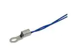
NTC Thermistors, Standard Lug Sensors, 150 °C
FEATURES
• 150 °C long term stability (5000 h dry heat)
• Easy mounting using ring tongue terminal
Available
• Rugged construction
• Cable with ETFE insulation according to
NEMA HP-3, type Z, rated 600 VRMS, cable test
voltage 3.4 kV
• AEC-Q200 qualified (grade 1)
• cULus recognized, file E148885
(UL category XGPU2/XGPU8)
• Material categorization: for definitions of compliance
please see www.vishay.com/doc?99912
LINKS TO ADDITIONAL RESOURCES
3D 3D
3D Models
Design Tools
Models
APPLICATIONS
Related
Documents
QUICK REFERENCE DATA
PARAMETER
Resistance value at 25 °C (1)
Tolerance on R25-value (1)
B25/85-value (1)
Tolerance on B25/85-value
Operating temperature range
at zero dissipation
Min. dielectric withstanding
voltage between terminals and lug
Min. insulation resistance between
terminals and lug at 500 VDC
Weight
VALUE
10K
± 1 to ± 2
3435, 3984
± 0.5 to ± 1
UNIT
Ω
%
K
%
-40 to +150
°C
2700
VAC
100
MΩ
2.0 to 3.2
g
Note
(1) Other R -values, B
25
25/85-values, and tolerances are available
upon request
AGENCY APPROVALS
• cUL certificate XGPU8.E148885
• ULus certificate XGPU2.E148885
Note
• Agency approval documents, please see:
www.vishay.com/ppg?29164&documents
DESIGN-IN SUPPORT
• Other resistance curves and tolerances are available on
request
• Consult Vishay for other lead length, other connector
crimping, or other features
https://info.vishay.com/vishay-ntc-modification-request
Suitable for surface sensing applications, especially when a
good electrical insulation and a good thermal contact with
the chassis is required for:
• Automotive equipment
• EV and battery management
• Power electronics, heat sink
• Consumer appliances
DESCRIPTION
A NTC thermistor chip is soldered to AWG#26
multi-stranded silver plated copper leads with ETFE
insulation and insulated with epoxy coating. The insulated
sensor is attached to a tin plated copper ring lug via a middle
buffer layer. The lead wires are twisted.
PACKAGING
The thermistors are packed in cardboard boxes; the
smallest packaging quantity is 200 units.
CAUTIONS AND WARNINGS ON MOUNTING
AND HANDLING
Please read the special instructions:
see www.vishay.com/doc?29221.
• By means of M3 (stud #3, #4) or M3,5 (stud #5, #6) screw.
Leads to be soldered or crimped
• The device is suitable for screwing e.g. on metal surface
• The leads are suitable for soldering e.g. on PCB
• 3D solid models: www.vishay.com/doc?29179
• NTC curve computation:
www.vishay.com/thermistors/ntc-rt-calculator/
Revision: 01-Mar-2022
Document Number: 29164
1
For technical questions, contact: nlr@vishay.com
THIS DOCUMENT IS SUBJECT TO CHANGE WITHOUT NOTICE. THE PRODUCTS DESCRIBED HEREIN AND THIS DOCUMENT
ARE SUBJECT TO SPECIFIC DISCLAIMERS, SET FORTH AT www.vishay.com/doc?91000
�NTCALUG01T
www.vishay.com
Vishay BCcomponents
DIMENSIONS in millimeters
T
Ø D2
Ø D3
Ø D4
Ø D1
L2
E
L3
L1
L1
L2
Ø D1
Ø D2
Ø D3
T
L3
E
D4
Refer to the
ordering
table
3.8 ± 1
3.7 +0.2 / -0
7.2 ± 0.2
5.6 +0.3 / -0.2
1.0
15.70 ± 0.3
6.2 ± 0.2
0.93 ± 0.1
ELECTRICAL DATA AND ORDERING INFORMATION
R25
(Ω)
R25B25/85B25/85
TOL.
TOL.
(K)
(± %)
(± %)
L1
(mm)
DESCRIPTION
UL
RECOG.
SAP MATERIAL AND ORDERING NUMBER
RoHS-COMPLIANT
WITH EXEMPTION (1)
RoHS-COMPLIANT (2)
10 000
1
3984
0.5
150 ± 10
NTC Lug01T 10K 1 % 3984 K
150 °C ETFE AWG26 150 mm
✓
NTCALUG01T103F
NTCALUG01T103FA
10 000
1
3435
1.0
150 ± 10
NTC Lug01T 10K 1 % 3435 K
150 °C ETFE AWG26 150 mm
✓
NTCALUG01T103FL
NTCALUG01T103FLA
10 000
2
3984
0.5
40 ± 5
NTC Lug01T 10K 2 % 3984 K
150 °C ETFE AWG26 40 mm
✓
NTCALUG01T103G400
NTCALUG01T103G400A
10 000
2
3984
0.5
150 ± 10
NTC Lug01T 10K 2 % 3984 K
150 °C ETFE AWG26 150 mm
✓
NTCALUG01T103G
NTCALUG01T103GA
10 000
2
3984
0.5
200 ± 10
NTC Lug01T 10K 2 % 3984 K
150 °C ETFE AWG26 200 mm
✓
NTCALUG01T103G201
NTCALUG01T103G201A
10 000
2
3984
0.5
500 ± 10
NTC Lug01T 10K 2 % 3984 K
150 °C ETFE AWG26 500 mm
✓
NTCALUG01T103G501
NTCALUG01T103G501A
Notes
Preferred versions for new designs
(1) RoHS exemption 7(c)-I: electrical and electronic components containing lead in a glass or ceramic other than dielectric ceramic in
capacitors, e.g. piezo-electronic devices, or in a glass or ceramic matrix compound.
(e2) The end conductor is dipped in tin-silver alloy solder
(2) RoHS I, RoHS II, RoHS III, without exemption, and lead (Pb)-free.
(e4) The end conductor is multistranded silver plated copper
Revision: 01-Mar-2022
Document Number: 29164
2
For technical questions, contact: nlr@vishay.com
THIS DOCUMENT IS SUBJECT TO CHANGE WITHOUT NOTICE. THE PRODUCTS DESCRIBED HEREIN AND THIS DOCUMENT
ARE SUBJECT TO SPECIFIC DISCLAIMERS, SET FORTH AT www.vishay.com/doc?91000
�Legal Disclaimer Notice
www.vishay.com
Vishay
Disclaimer
ALL PRODUCT, PRODUCT SPECIFICATIONS AND DATA ARE SUBJECT TO CHANGE WITHOUT NOTICE TO IMPROVE
RELIABILITY, FUNCTION OR DESIGN OR OTHERWISE.
Vishay Intertechnology, Inc., its affiliates, agents, and employees, and all persons acting on its or their behalf (collectively,
“Vishay”), disclaim any and all liability for any errors, inaccuracies or incompleteness contained in any datasheet or in any other
disclosure relating to any product.
Vishay makes no warranty, representation or guarantee regarding the suitability of the products for any particular purpose or
the continuing production of any product. To the maximum extent permitted by applicable law, Vishay disclaims (i) any and all
liability arising out of the application or use of any product, (ii) any and all liability, including without limitation special,
consequential or incidental damages, and (iii) any and all implied warranties, including warranties of fitness for particular
purpose, non-infringement and merchantability.
Statements regarding the suitability of products for certain types of applications are based on Vishay's knowledge of typical
requirements that are often placed on Vishay products in generic applications. Such statements are not binding statements
about the suitability of products for a particular application. It is the customer's responsibility to validate that a particular product
with the properties described in the product specification is suitable for use in a particular application. Parameters provided in
datasheets and / or specifications may vary in different applications and performance may vary over time. All operating
parameters, including typical parameters, must be validated for each customer application by the customer's technical experts.
Product specifications do not expand or otherwise modify Vishay's terms and conditions of purchase, including but not limited
to the warranty expressed therein.
Hyperlinks included in this datasheet may direct users to third-party websites. These links are provided as a convenience and
for informational purposes only. Inclusion of these hyperlinks does not constitute an endorsement or an approval by Vishay of
any of the products, services or opinions of the corporation, organization or individual associated with the third-party website.
Vishay disclaims any and all liability and bears no responsibility for the accuracy, legality or content of the third-party website
or for that of subsequent links.
Except as expressly indicated in writing, Vishay products are not designed for use in medical, life-saving, or life-sustaining
applications or for any other application in which the failure of the Vishay product could result in personal injury or death.
Customers using or selling Vishay products not expressly indicated for use in such applications do so at their own risk. Please
contact authorized Vishay personnel to obtain written terms and conditions regarding products designed for such applications.
No license, express or implied, by estoppel or otherwise, to any intellectual property rights is granted by this document or by
any conduct of Vishay. Product names and markings noted herein may be trademarks of their respective owners.
© 2022 VISHAY INTERTECHNOLOGY, INC. ALL RIGHTS RESERVED
Revision: 01-Jan-2022
1
Document Number: 91000
�