NTCALUG03A / LUG39A Mini Lug Series
www.vishay.com
Vishay BCcomponents
NTC Thermistors, Mini Lug Sensors
FEATURES
LINKS TO ADDITIONAL RESOURCES
3D 3D
3D Models
Design Tools
Models
Related
Documents
QUICK REFERENCE DATA
PARAMETER
Resistance value at 25 °C
Tolerance on R25-value
VALUE
UNIT
10K to 47K
Ω
± 2 to ± 3
%
• Fast time response for surface applications
compared to industry standard NTC lug sensors
Available
• Reduced thermal gradient, due to the use of
small dimensions and nickel conductor,
allowing for an accurate surface temperature
measurement
• The sensor is not suitable for being permanently
in contact with water or liquids
• Small size connector and small lug ring tongue terminal,
allowing for temperature sensing at locations where only
limited space is available
• Optional connector, rated +85 °C, tin plated (e3)
• AEC-Q200 qualified available (grade 1)
• cULus recognized, file E148885
(UL category XGPU2/XGPU8)
• Material categorization: for definitions of compliance
please see www.vishay.com/doc?99912
B25/85-value
3740 to 3984
K
Tolerance on B25/85-value
± 0.5 to ± 1.5
%
APPLICATIONS
°C
Thermistors used for surface temperature sensing and
control in:
Operating temperature range:
At zero dissipation
-40 to +125
≈ 3.5
s
Thermal time constant τ
≈5
s
Dissipation factor δ
10
mW/K
1000
VAC
40 / 125 / 56
-
Response time
Min. dielectric withstanding
voltage between terminals
and lug
Climatic category
(LCT / UCT / days)
• Computer equipment
• MOSFETS, IC’s, power electronics, heatsink temperature
control, LED emitter heat-sink control
• Consumer appliances
• Industrial equipment
• Automotive equipment
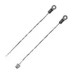
DESCRIPTION
Weight
without connector
~ 0.5
g
with connector
~ 0.6
g
AGENCY APPROVALS
• cUL certificate XGPU8.E148885
• ULus certificate XGPU2.E148885
Note
Miniature insulated chip thermistor with a negative
temperature coefficient soldered to AWG#32 silver plated
nickel and insulated cables, and mounted inside a mini lug
tin plated copper barrel.
PACKAGING
Available in plastic bags.
• Agency approval documents, please see:
www.vishay.com/ppg?29114&documents
CAUTIONS AND WARNINGS ON MOUNTING
AND HANDLING
DESIGN-IN SUPPORT
Please read the special instructions:
see www.vishay.com/doc?29221.
• Other resistance curves and tolerances are available on
request
• Consult Vishay for other lead length, other connector
crimping, or other features
https://info.vishay.com/vishay-ntc-modification-request
• 3D solid models: www.vishay.com/doc?29147
• NTC curve computation:
www.vishay.com/thermistors/ntc-rt-calculator/
Revision: 21-Feb-2022
• The sensor NTCALUG03A can be mounted by means of a
screw M2 (stud #1, #2), or a screw M3 (stud #3, #4) for
NTCALUG39A
• For the type without connector, the electrical connection
can be made by soldering, crimping, or welding
• For the type with connector, see section Mounting
Connector
Document Number: 29114
1
For technical questions, contact: nlr@vishay.com
THIS DOCUMENT IS SUBJECT TO CHANGE WITHOUT NOTICE. THE PRODUCTS DESCRIBED HEREIN AND THIS DOCUMENT
ARE SUBJECT TO SPECIFIC DISCLAIMERS, SET FORTH AT www.vishay.com/doc?91000
�NTCALUG03A / LUG39A Mini Lug Series
www.vishay.com
Vishay BCcomponents
DIMENSIONS in millimeters
Ø D2
Ø D1
Ø D4
L4
Ø D3
4.
L2
1. 2.
L3
3.
L1
T
5.
P
(3.10)
L1
MODEL
L1
L2
L3
L4
L1 + L 3
(item without
connector)
Ø D1
Ø D2
Ø D3
Ø D4
T
PITCH P
NTCALUG03A
70 ± 5 4 ± 1 11.5 ± 0.5
8.8 ± 0.3
81.5 ± 5
2.2 ± 0.3
5.5 ± 0.3
3.4 ± 0.3
0.35 ± 0.1
0.8 ± 0.1
1.5 ± 0.3
NTCALUG39A
70 ± 5 4 ± 1 11.5 ± 0.5
8.8 ± 0.3
81.5 ± 5
3.2 ± 0.3
5.5 ± 0.3
3.4 ± 0.3
0.35 ± 0.1
0.8 ± 0.1
1.5 ± 0.3
Notes
1. Vishay thermistor chip NTC, with epoxy coating
2. Metal ring lug, tin plated
3. Insulated leads: AWG#32, monostranded, diam 0.20 mm, silver plated nickel, ETFE insulated, diameter 0.35 mm
4. End wire stripped
5. 2-poles JST ZHR-2 connector crimped
ELECTRICAL DATA AND ORDERING INFORMATION
R25B25/85B
TOL. 25/85 TOL.
(K)
(± %)
(± %)
R25
(Ω)
DESCRIPTION
UL
RECOG.
SAP MATERIAL AND ORDERING NUMBER
RoHS-COMPLIANT
WITH EXEMPTION (1)
RoHS-COMPLIANT
NTC Mini Lug M2 10K 2 % 3984 K 0.5 %
✓
NTCALUG03A103G
NTCALUG03A103GA
0.5
NTC Mini Lug M3 10K 2 % 3984 K 0.5 %
✓
NTCALUG39A103G
NTCALUG39A103GA
✓
NTCALUG03A103GC NTCALUG03A103GCA
NTCALUG39A103GC NTCALUG39A103GCA
10 000
2
3984
0.5
10 000
2
3984
10 000
2
3984
0.5
NTC Mini Lug M2 10K 2 % 3984 K 0.5 %
with connector
10 000
2
3984
0.5
NTC Mini Lug M3 10K 2 % 3984 K 0.5 %
with connector
✓
10 000
3
3984
0.5
NTC Mini Lug M2 10K 3 % 3984 K 0.5 %
✓
NTCALUG03A103H
NTCALUG03A103HA
10 000
3
3984
0.5
NTC Mini Lug M2 10K 3 % 3984 K 0.5 %
with connector
✓
NTCALUG03A103HC
NTCALUG03A103HCA
12 000
3
3740
1.5
NTC Mini Lug M2 12K 3 %
NTCALUG03A123H
NTCALUG03A123HA
NTCALUG03A123HC
NTCALUG03A123HCA
12 000
3
3740
1.5
NTC Mini Lug M2 12K 3 %
with connector
47 000
3
3740
1.5
NTC Mini Lug M2 47K 3 %
NTCALUG03A473H
NTCALUG03A473HA
47 000
3
3740
1.5
NTC Mini Lug M2 47 kΩ 3 %
with connector
NTCALUG03A473HC
NTCALUG03A473HCA
Notes
Preferred versions for new designs
(1) RoHS exemption 7(c)-I: electrical and electronic components containing lead in a glass or ceramic other than dielectric ceramic in
capacitors, e.g. piezo-electronic devices, or in a glass or ceramic matrix compound
Revision: 21-Feb-2022
Document Number: 29114
2
For technical questions, contact: nlr@vishay.com
THIS DOCUMENT IS SUBJECT TO CHANGE WITHOUT NOTICE. THE PRODUCTS DESCRIBED HEREIN AND THIS DOCUMENT
ARE SUBJECT TO SPECIFIC DISCLAIMERS, SET FORTH AT www.vishay.com/doc?91000
�NTCALUG03A / LUG39A Mini Lug Series
www.vishay.com
Vishay BCcomponents
MOUNTING CONNECTOR
• Important mounting and handling instructions: see www.vishay.com/doc?29221
• For the type with connector, the JST ZHR-2 connector can mate with following counter-connectors (1):
A. One of the PCB connector - through hole:
• JST B 2B-ZR (top entry)
• JST S 2B-ZR (side entry)
• JST B 2B-ZR-3.4 (top entry, for 1.6 mm board)
• JST S 2B-ZR-3.4 (side entry, for 1.6 mm board)
B. One of the PCB board connector - SMT surface mount:
• JST S 2B-ZR-SM2-TF (SM2 side entry)
• JST B 2B-ZR-SM3-TF (SM3 top entry)
• JST S 2B-ZR-SM3A-TF (SM3 side entry)
• JST B 2B-ZR-SM4-TF (SM4 top entry)
• JST S 2B-ZR-SM4A-TF (SM4 side entry)
C. The wire-to-wire connector:
• JST ZMR-02 housing (x 1) + JST SMM-003T-P0.5 terminals (x 2)
Note
(1) Additional details and dimensions can be found in JST ZH and JST ZM datasheets
Revision: 21-Feb-2022
Document Number: 29114
3
For technical questions, contact: nlr@vishay.com
THIS DOCUMENT IS SUBJECT TO CHANGE WITHOUT NOTICE. THE PRODUCTS DESCRIBED HEREIN AND THIS DOCUMENT
ARE SUBJECT TO SPECIFIC DISCLAIMERS, SET FORTH AT www.vishay.com/doc?91000
�Legal Disclaimer Notice
www.vishay.com
Vishay
Disclaimer
ALL PRODUCT, PRODUCT SPECIFICATIONS AND DATA ARE SUBJECT TO CHANGE WITHOUT NOTICE TO IMPROVE
RELIABILITY, FUNCTION OR DESIGN OR OTHERWISE.
Vishay Intertechnology, Inc., its affiliates, agents, and employees, and all persons acting on its or their behalf (collectively,
“Vishay”), disclaim any and all liability for any errors, inaccuracies or incompleteness contained in any datasheet or in any other
disclosure relating to any product.
Vishay makes no warranty, representation or guarantee regarding the suitability of the products for any particular purpose or
the continuing production of any product. To the maximum extent permitted by applicable law, Vishay disclaims (i) any and all
liability arising out of the application or use of any product, (ii) any and all liability, including without limitation special,
consequential or incidental damages, and (iii) any and all implied warranties, including warranties of fitness for particular
purpose, non-infringement and merchantability.
Statements regarding the suitability of products for certain types of applications are based on Vishay's knowledge of typical
requirements that are often placed on Vishay products in generic applications. Such statements are not binding statements
about the suitability of products for a particular application. It is the customer's responsibility to validate that a particular product
with the properties described in the product specification is suitable for use in a particular application. Parameters provided in
datasheets and / or specifications may vary in different applications and performance may vary over time. All operating
parameters, including typical parameters, must be validated for each customer application by the customer's technical experts.
Product specifications do not expand or otherwise modify Vishay's terms and conditions of purchase, including but not limited
to the warranty expressed therein.
Hyperlinks included in this datasheet may direct users to third-party websites. These links are provided as a convenience and
for informational purposes only. Inclusion of these hyperlinks does not constitute an endorsement or an approval by Vishay of
any of the products, services or opinions of the corporation, organization or individual associated with the third-party website.
Vishay disclaims any and all liability and bears no responsibility for the accuracy, legality or content of the third-party website
or for that of subsequent links.
Except as expressly indicated in writing, Vishay products are not designed for use in medical, life-saving, or life-sustaining
applications or for any other application in which the failure of the Vishay product could result in personal injury or death.
Customers using or selling Vishay products not expressly indicated for use in such applications do so at their own risk. Please
contact authorized Vishay personnel to obtain written terms and conditions regarding products designed for such applications.
No license, express or implied, by estoppel or otherwise, to any intellectual property rights is granted by this document or by
any conduct of Vishay. Product names and markings noted herein may be trademarks of their respective owners.
© 2022 VISHAY INTERTECHNOLOGY, INC. ALL RIGHTS RESERVED
Revision: 01-Jan-2022
1
Document Number: 91000
�