P13SM
www.vishay.com
Vishay Sfernice
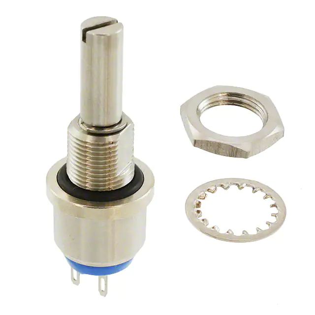
Fully Sealed Container Cermet Potentiometers
Submarine Applications
FEATURES
• High power rating 1.5 W at 70 °C
• Stainless steel shaft and bushing to endure sea
salt water immersion
• Fully sealed IP68 on panel
• Tight temperature coefficient (± 75 ppm/°C typical)
• Material categorization: for definitions of compliance
please see www.vishay.com/doc?99912
P13SM is designed for applications which need to set
electrical parameters with an immersed potentiometer in
deep water conditions up to 30 m (100 feet).
QUICK REFERENCE DATA
Multiple module
No
Switch module
n/a
Detent module
n/a
Special electrical laws
A: linear, L: logarithmic, F: reverse logarithmic
Sealing level
IP 68
Lifespan
25K cycles
DIMENSIONS in millimeters (inches) ± 0.5 mm (± 0.02")
P13SM N
Thread M10 x 0.75
14.6 max. 10.3
Panel Cutout
1.6
Slot 1 x 1.8 deep
0.3
Ø6
Ø 16 Ø 14
Ø 10.5
2 5.08
6.9 ± 0.2
5.08
FG = 16
5
1.6
Ø 1.5 (1)
0.8
FL = 25
2.4
FR = 50
P13SM B
1
Panel Cutout
1/4-32 UNEF-2A
13.2 max.
Ø 1.5 (1)
1.6
Slot 0.6 x 1 deep
Ø 12.6
(0.5")
Ø 3.17 (0.125")
9.52
5
BB = 12.7
BJ = 22.2
0.3
2 5.08
3.9 ± 0.2
5.08
Ø 6.5
1.6
0.8
2.4
Note
(1) CAUTION: Ø 1.5 of panel cut out must not be fully through-hole
Undergoes European Quality Insurance System
Revision: 29-Jul-2021
Document Number: 51064
1
For technical questions, contact: sferpottrimmers@vishay.com
THIS DOCUMENT IS SUBJECT TO CHANGE WITHOUT NOTICE. THE PRODUCTS DESCRIBED HEREIN AND THIS DOCUMENT
ARE SUBJECT TO SPECIFIC DISCLAIMERS, SET FORTH AT www.vishay.com/doc?91000
�P13SM
www.vishay.com
Vishay Sfernice
ELECTRICAL SPECIFICATIONS
Resistive element
Cermet
Electrical travel
270° ± 10°
Linear taper
22 Ω to 10 MΩ
Logarithmic taper
1 kΩ to 2.2 MΩ
Resistance range
Standard series E3
1, 2.2, 4.7, and on request 1, 2, 5
Standard
± 20 %
Tolerance
On request
± 10 % to ± 5 %
Taper
% TOTAL RESISTANCE
100
80
F
60
A
L
40
20
0
0
20
40
60
80
100
% CLOCKWISE SHAFT ROTATION
c
a
Circuit diagram
(3)
(1)
cw
b
(2)
1.5
Linear
1.5 W at 70 °C
Power rating
Logarithmic
0.75 W at 70 °C
POWER IN W
LIN. TAPER A
1
LOG. TAPER
L and F
0.5
0
0
20
40
60 70 80
100
120 140
AMBIENT TEMPERATURE IN °C
Temperature coefficient (typical)
Limiting element voltage (linear law)
Contact resistance variation
End resistance (typical)
± 150 ppm/°C
For values ≥ 100 Ω and in temperature range +20 °C to +70 °C,
the typical temperature coefficient is ± 75 ppm/°C
350 V
3 % Rn or 3 Ω
1Ω
Dielectric strength (RMS)
2000 V
Insulation resistance (300 VDC)
106 MΩ
Independent linearity (typical)
±5%
Revision: 29-Jul-2021
Document Number: 51064
2
For technical questions, contact: sferpottrimmers@vishay.com
THIS DOCUMENT IS SUBJECT TO CHANGE WITHOUT NOTICE. THE PRODUCTS DESCRIBED HEREIN AND THIS DOCUMENT
ARE SUBJECT TO SPECIFIC DISCLAIMERS, SET FORTH AT www.vishay.com/doc?91000
�P13SM
www.vishay.com
Vishay Sfernice
STANDARD RESISTANCE ELEMENT DATA
LINEAR TAPER
LOGS TAPED
MAX.
POWER
AT 70 °C
MAX.
WORKING
VOLTAGE
MAX. CUR.
THROUGH
WIPER
MAX.
POWER
AT 70 °C
MAX.
WORKING
VOLTAGE
MAX. CUR.
THROUGH
WIPER
TYPICAL
TCR
-55 °C
+125 °C
W
V
mA
W
V
mA
ppm/°C
22
1.5
5.74
261
-
-
-
47
1.5
8.4
177
-
-
-
100
1.5
12.2
122
-
-
-
220
1.5
18.2
82.6
-
-
-
470
1.5
26.5
56.5
-
-
-
STANDARD
RESISTANCE
VALUES
Ω
1K
1.5
38.7
38.7
0.75
27
27
2.2K
1.5
57.5
26.1
0.75
40
18
4.7K
1.5
84
17.9
0.75
59
12
10K
1.5
122.5
12.2
0.75
87
8.7
22K
1.5
182
8.26
0.75
128
5.8
47K
1.5
265
5.65
0.75
187
3.9
100K
1.22
350
3.5
0.75
273
2.7
220K
0.56
350
1.6
0.56
350
1.6
470K
0.26
350
0.74
0.26
350
0.74
1M
0.12
350
0.35
0.12
350
0.35
2.2M
0.05
350
0.16
0.05
350
0.16
4.7M
0.026
350
0.074
-
-
-
10M
0.012
350
0.035
-
-
-
± 150
MECHANICAL SPECIFICATIONS
Mechanical travel
Style B
300° ± 5°
Style N
310° ± 5°
Operating torque (typical)
2 Ncm
2.85 oz. inch
Style B
35 Ncm max.
3.1 lb inch max.
Style N
80 Ncm max.
7.1 lb inch max.
Style B
80 Ncm min., 150 Ncm max.
7 lb inch min., 13.3 lb inch max.
Style N
80 Ncm min., 250 Ncm max.
7 lb inch min., 22.1 lb inch max.
8 g to 27 g
0.3 oz. to 1 oz.
End stop torque
Tightening torque of mounting nut
Unit weight
Terminals
e3: pure Sn
ENVIRONMENTAL SPECIFICATIONS
Temperature range
Climatic category
Sealing
Panel sealing
Revision: 29-Jul-2021
-55 °C to +125 °C
55 / 125 / 56
Fully sealed - container IP68
Immersion at 30 m (100 feet) in sea salt water or clear water
Document Number: 51064
3
For technical questions, contact: sferpottrimmers@vishay.com
THIS DOCUMENT IS SUBJECT TO CHANGE WITHOUT NOTICE. THE PRODUCTS DESCRIBED HEREIN AND THIS DOCUMENT
ARE SUBJECT TO SPECIFIC DISCLAIMERS, SET FORTH AT www.vishay.com/doc?91000
�P13SM
www.vishay.com
Vishay Sfernice
OPTIONS
Special feature command shaft
Length is measured from the mounting surface to the free end of the shaft. The screwdriver slot is aligned
with the wiper within ± 10°. Special shafts are available, in accordance to drawings supplied by
customers. We recommend that customers should not machine tool shafts, in order to avoid damage.
Bending or torsion of terminals should also be avoided.
MARKING
Printed:
• Vishay trademark
• Part number (including ohmic value code, tolerance code and resistance law)
• Manufacturing date
• Marking of terminals a
PACKAGING
In box
Packaging quantity depending on shafts:
• Box of 5 pieces for shaft FR (code BO5)
• Box of 10 pieces for shaft FG or FL (code BO10)
• Box of 15 pieces for shaft BJ (code BO15)
• Box of 25 pieces for shaft BB (code BO25)
Hardware: nuts, washer, and O-ring are separately supplied (not mounted on the potentiometer), in a small bag placed in the packaging.
PERFORMANCE
TESTS
CONDITIONS
TYPICAL VALUES AND DRIFTS
ΔRT/RT (%)
ΔR1-2/R1-2 (%)
OTHER
1000 h at rated power
90'/30' - ambient temperature 70 °C
±1%
-
Contact res. variation: < 3 % Rn
Phase A dry heat 125 °C
Phase B damp heat
Phase C cold -55 °C
Phase D damp heat 5 cycles
± 0.5 %
±1%
-
Damp heat, steady state
56 days
40 °C, 93 % HR
± 0.5 %
±1%
Dielectric strength: 1000 V
Insulation resistance: > 104 MΩ
Change of temperature
5 cycles
-55 °C at +125 °C
± 0.5 %
-
-
Electrical endurance
Climatic sequence
Mechanical endurance
Shock
Vibration
25 000 cycles
±3%
-
Contact res. variation: < 2 % Rn
50 g’s at 11 ms
3 successive shocks
in 3 directions
± 0.1 %
± 0.2 %
-
10 Hz to 55 Hz
0.75 mm or 10 g’s
during 6 h
± 0.1 %
-
ΔV1-2/V1-3 < ± 0.2 %
Note
• Nothing stated herein shall be construed as a guarantee of quality or durability
Revision: 29-Jul-2021
Document Number: 51064
4
For technical questions, contact: sferpottrimmers@vishay.com
THIS DOCUMENT IS SUBJECT TO CHANGE WITHOUT NOTICE. THE PRODUCTS DESCRIBED HEREIN AND THIS DOCUMENT
ARE SUBJECT TO SPECIFIC DISCLAIMERS, SET FORTH AT www.vishay.com/doc?91000
�P13SM
www.vishay.com
Vishay Sfernice
ORDERING INFORMATION (Part Number)
P
1
3
MODEL
S
M
BUSHING
P13SM
Ø
L
N
F
SHAFT
Ø
L
Shaft
Ø
BB 3.17 12.7
6
BJ 3.17 22.2
N 10 10.3
B 6.35 9.52 3.17
FG
6
16
FL
6
25
FR
6
50
AP
Custom
L
S
1
0
SHAFT
STYLE
OHMIC
VALUE
S = slotted
Linear law
from 22 Ω
to 10 MΩ
On request:
R = round
F = flat
D = custom
Logarithmic
law from
1 kΩ to 2.2 MΩ
3
M
A
E
TOLERANCE
TAPER
SPECIAL
M = 20 %
A = linear
L = clockwise
logarithmic
F = inverse
clockwise
logarithmic
E=
locating peg
or
special code
given by
Vishay
On request:
K = 10 %
J=5%
103 = 10 kΩ
PART NUMBER DESCRIPTION (for information only)
P13SM
N
E
FL
MODEL BUSHING SPECIAL SHAFT
S
10K
20 %
A
BO10
e3
SHAFT
LEAD
VALUE TOLERANCE TAPER SPECIAL PACKAGING SHAFT SPECIAL
STYLE
(Pb)-FREE
RELATED DOCUMENTS
APPLICATION NOTES
Potentiometers and Trimmers
www.vishay.com/doc?51001
Guidelines for Vishay Sfernice Resistive and Inductive Components
www.vishay.com/doc?52029
Revision: 29-Jul-2021
Document Number: 51064
5
For technical questions, contact: sferpottrimmers@vishay.com
THIS DOCUMENT IS SUBJECT TO CHANGE WITHOUT NOTICE. THE PRODUCTS DESCRIBED HEREIN AND THIS DOCUMENT
ARE SUBJECT TO SPECIFIC DISCLAIMERS, SET FORTH AT www.vishay.com/doc?91000
�Legal Disclaimer Notice
www.vishay.com
Vishay
Disclaimer
ALL PRODUCT, PRODUCT SPECIFICATIONS AND DATA ARE SUBJECT TO CHANGE WITHOUT NOTICE TO IMPROVE
RELIABILITY, FUNCTION OR DESIGN OR OTHERWISE.
Vishay Intertechnology, Inc., its affiliates, agents, and employees, and all persons acting on its or their behalf (collectively,
“Vishay”), disclaim any and all liability for any errors, inaccuracies or incompleteness contained in any datasheet or in any other
disclosure relating to any product.
Vishay makes no warranty, representation or guarantee regarding the suitability of the products for any particular purpose or
the continuing production of any product. To the maximum extent permitted by applicable law, Vishay disclaims (i) any and all
liability arising out of the application or use of any product, (ii) any and all liability, including without limitation special,
consequential or incidental damages, and (iii) any and all implied warranties, including warranties of fitness for particular
purpose, non-infringement and merchantability.
Statements regarding the suitability of products for certain types of applications are based on Vishay's knowledge of typical
requirements that are often placed on Vishay products in generic applications. Such statements are not binding statements
about the suitability of products for a particular application. It is the customer's responsibility to validate that a particular product
with the properties described in the product specification is suitable for use in a particular application. Parameters provided in
datasheets and / or specifications may vary in different applications and performance may vary over time. All operating
parameters, including typical parameters, must be validated for each customer application by the customer's technical experts.
Product specifications do not expand or otherwise modify Vishay's terms and conditions of purchase, including but not limited
to the warranty expressed therein.
Hyperlinks included in this datasheet may direct users to third-party websites. These links are provided as a convenience and
for informational purposes only. Inclusion of these hyperlinks does not constitute an endorsement or an approval by Vishay of
any of the products, services or opinions of the corporation, organization or individual associated with the third-party website.
Vishay disclaims any and all liability and bears no responsibility for the accuracy, legality or content of the third-party website
or for that of subsequent links.
Except as expressly indicated in writing, Vishay products are not designed for use in medical, life-saving, or life-sustaining
applications or for any other application in which the failure of the Vishay product could result in personal injury or death.
Customers using or selling Vishay products not expressly indicated for use in such applications do so at their own risk. Please
contact authorized Vishay personnel to obtain written terms and conditions regarding products designed for such applications.
No license, express or implied, by estoppel or otherwise, to any intellectual property rights is granted by this document or by
any conduct of Vishay. Product names and markings noted herein may be trademarks of their respective owners.
© 2022 VISHAY INTERTECHNOLOGY, INC. ALL RIGHTS RESERVED
Revision: 01-Jan-2022
1
Document Number: 91000
�


 工商网监
湘ICP备2023018690号
工商网监
湘ICP备2023018690号
