PLTT
www.vishay.com
Vishay Dale Thin Film
Precision Low TCR High Temperature Thin Film Resistor,
Surface Mount Chip, ± 5 ppm/°C TCR, 0.02 % Tolerance
FEATURES
• PLTT0603 case size is qualified to AEC-Q200
for automotive applications
• -55 °C to 215 °C operating temperature range
• TCR of ± 5 ppm/°C standard
Available
• Tolerances to ± 0.02 %
• Anti corrosion resistant film with (SPM) special
passivation method
• Stable film and performance characteristics
• 0.5 % max. at 2000 h, 215 °C, 25 % rated power
• Non-standard resistance values available
• Very low noise and voltage coefficient
(< -30 dB, 0.1 ppm/V)
• UL 94 V-0 flame resistant
• Gold terminations (10 μ" to 20 μ")
• Material categorization: for definitions of compliance
please see www.vishay.com/doc?99912
Vishay’s proven precision thin film wraparound resistors will
meet your exact requirements. These resistors are ideal for
use in oil industry precision applications requiring low noise,
long term stability under high temperature, ultra low
temperature coefficient of resistance, and low voltage
coefficient. The chip resistors are available in any resistance
ohmic value in the range specified below.
CONSTRUCTION
SPM Passivation
Enhancement
Available
Passivated Nichrome
Resistive Film
Plated
Gold (10 μ" to 20 μ")
TYPICAL PERFORMANCE
ABSOLUTE
Nickel Barrier
High Purity
Alumina Substrate
Adhesion Layer
TCR
5
TOL.
0.02
STANDARD ELECTRICAL SPECIFICATIONS
TEST
Material
SPECIFICATIONS
CONDITIONS
Passivated nichrome
-
50 to 3 M
-
± 5 ppm/°C
-55 °C to +215 °C
± 0.1 % to ± 0.02 %
+25 °C
R ± 0.5 %
2000 h at 215 °C, 25 % rated power
-
-
± 0.1 ppm/V (typical)
-
Resistance Range
TCR: Absolute
Tolerance: Absolute
Stability: Absolute
Stability: Ratio
Voltage Coefficient
Working Voltage
100 V to 200 V
-
Operating Temperature Range
-55 °C to +215 °C
-
Storage Temperature Range
-55 °C to +215 °C
-
Noise
< - 35 dB (typical)
-
R ± 0.01 %
1 year at +25 °C
Shelf Life Stability: Absolute
COMPONENT RATINGS
CASE SIZE
POWER RATING
AT 70 °C
(mW)
WORKING VOLTAGE
(V)
RESISTANCE RANGE
()
0603
150
75
75 to 130K
0805
250
100
250 to 260K
1206
400
200
500 to 775K
2010
800
200
500 to 2M
2512
1000
200
500 to 3M
Note
• Consult factory for additional case size
Revision: 08-Jul-16
Document Number: 60082
1
For technical questions, contact: thinfilm@vishay.com
THIS DOCUMENT IS SUBJECT TO CHANGE WITHOUT NOTICE. THE PRODUCTS DESCRIBED HEREIN AND THIS DOCUMENT
ARE SUBJECT TO SPECIFIC DISCLAIMERS, SET FORTH AT www.vishay.com/doc?91000
�PLTT
www.vishay.com
Vishay Dale Thin Film
DIMENSIONS in inches
D
W
T
E
L
CASE SIZE
TERM
L
W
T
D
E
0603
G
0.064 ± 0.006
0.032 ± 0.005
0.015 to 0.033
0.012 ± 0.005
0.015 ± 0.005
0805
G
0.080 ± 0.006
0.050 ± 0.005
0.015 to 0.033
0.016 ± 0.008
0.015 ± 0.005
1206
G
0.126 ± 0.008
0.063 ± 0.005
0.015 to 0.033
0.020 + 0.005/- 0.010
0.020 + 0.005/- 0.010
2010
G
0.209 ± 0.009
0.098 ± 0.005
0.015 to 0.033
0.020 ± 0.005
0.020 ± 0.005
2512
G
0.259 ± 0.009
0.124 ± 0.005
0.015 to 0.033
0.020 ± 0.005
0.020 ± 0.005
ENVIRONMENTAL TESTS - MIL-PRF-55342
CONDITIONS
TYPICAL VISHAY
PERFORMANCE
Thermal Shock
MIL-STD-202 method 107 Cond F, -65 °C to +150 °C
± 0.02 %
Short Time Overload
MIL-PRF-55342 Para 4.8.6, 2.5x rated working voltage
± 0.01 %
ENVIRONMENTAL TEST
Low Temperature Operation
MIL-PRF-55342 Para 4.8.5, -65 °C
± 0.01 %
Resistance to Soldering Heat
MIL-STD-202 method 210
± 0.01 %
Moisture Resistance
MIL-STD-202 method 106, no power applied
± 0.02 %
MIL-PRF-55342 Para 4.8.7, at 150 °C for 100 h
± 0.02 %
Life
MIL-STD-202 method 108, 25 % rated power
for 2000 h at 215 °C
± 0.50 %
TCR
MIL-STD-202 method 304
± 5 ppm/°C
High Temperature Exposure
ENVIRONMENTAL TESTS - AEC-Q200 PLTT0603 Case Size Only
ENVIRONMENTAL TEST
CONDITIONS
TYPICAL VISHAY
PERFORMANCE
High temperature storage
MIL-STD-202 method 108, 1000 h at 125 °C
± 0.10 %
Temperature cycling
JESD22 method JA-104, 1000 cycles,
-55 °C to +155 °C
± 0.25 %
Moisture resistance
MIL-STD-202 method 106, no power applied
± 0.10 %
Biased humidity
MIL-STD-202 method 103, 1000 h at 85 °C,
85 % RH, 10 % rated power
± 0.20 %
MIL-STD-202 method 108,
1000 h at 175 °C, 50 % rated power
± 0.50 %
MIL-STD-202 method 213, condition C
± 0.02 %
Life
Mechanical shock
Vibration
MIL-STD-202 method 204, 10 Hz to 2 kHz
± 0.02 %
MIL-STD-202 method 210, condition B
± 0.02 %
Electrostatic discharge
AEC-Q200-002, human body (< 1 k: 1 kV; > 1 k: 2 kV)
< 1 k: 1 kV; > 1 k: 2 kV
Solderability
MIL-STD-883 method 2003 para 2.3.1 and J-STD-002
Pass
MIL-STD-202 method 304
± 5 ppm /°C
MIL-PRF-55342, 0.5 kg for 30 s minimun
Pass
AEC-Q200-001 para 4.0
Pass
Resistance to soldering heat
TCR
Die shear
Flame retardance
Revision: 08-Jul-16
Document Number: 60082
2
For technical questions, contact: thinfilm@vishay.com
THIS DOCUMENT IS SUBJECT TO CHANGE WITHOUT NOTICE. THE PRODUCTS DESCRIBED HEREIN AND THIS DOCUMENT
ARE SUBJECT TO SPECIFIC DISCLAIMERS, SET FORTH AT www.vishay.com/doc?91000
�PLTT
www.vishay.com
Vishay Dale Thin Film
DERATING CURVE
Percent of Rated Power
100
75
50
25
0
0
70
175
215
230
Ambient Temperature °C
PLTT0805 50 k STABILITY TEST RESULTS
0.50
0.50
0.40
0.40
0.30
0.30
Maximum Δ (%)
Maximum Δ (%)
PLTT0805 500 STABILITY TEST RESULTS
0.20
0.10
0.00
- 0.10
- 0.30
- 0.40
- 0.50
0
0.10
0.00
- 0.10
Test Conditions:
Case Size: 0805
Resistance Value: 500 Ω
Applied Power: 25 % of rated power
Test Chamber Temperature: 215 °C
- 0.20
0.20
Test Conditions:
Case Size: 0805
Resistance Value: 50 kΩ
Applied Power: 25 % of rated power
Test Chamber Temperature: 215 °C
- 0.20
- 0.30
- 0.40
- 0.50
125 250 425 500 750 1000 1100 1250 1525 1775 2000
0
125 250 425 500 750 1000 1100 1250 1525 1775 2000
Time on Test (h)
Time on Test (h)
Note
• Performance obtained with following mounting conditions
PCB: Polymide IPC-7831A STD land patterns
Solder paste: PbSnAg (93.5/5/1.5)
GLOBAL PART NUMBER INFORMATION
P
L
T
T
0
GLOBAL
MODEL
CASE
SIZE
TCR
CHARACTERISTIC
PLTT
0603
0805
1206
2010
2512
Z = ± 5 ppm/°C
8
0
5
Z
1
0
0
1
Q
G
T
1
RESISTANCE
TOLERANCE
TERMINATION
PACKAGING
The first 3 digits are
significant figures and
the last digit specifies
the number of zeros to
follow. “R” designates
the decimal point.
Example:
1001 = 1 k
2500 = 250
Special values with more
than 4 significant figures,
use a R for value below
1 k and a K for values
greater than 1 k to
signify a decimal point.
982R6 = 982.6
532R41 = 532.41
Q=
± 0.02 % (1)
A = ± 0.05 %
B = ± 0.1 %
D = ± 0.5 %
F=±1%
G=±2%
G = Wraparound Gold
over Ni barrier
(10 μ" min. Au)
WS = WAFFLE
WI = 100 min./1mult
(item single lot date code)
WP = 100 min./1mult
(package unit single lot
date code)
TAPE AND REEL
T0 = 100 min., 100 mult
T1 = 1000 min., 1000 mult
T5 = 500 min., 500 mult
TF = Full reel
TS = 100 min., 1 mult
TI = 100 min./1mult
(item single lot date code)
TP = 100 min., 1 mult
(package unit single lot
date code)
Note
Q tolerances are available only for resistance values 250 .
(1)
Revision: 08-Jul-16
Document Number: 60082
3
For technical questions, contact: thinfilm@vishay.com
THIS DOCUMENT IS SUBJECT TO CHANGE WITHOUT NOTICE. THE PRODUCTS DESCRIBED HEREIN AND THIS DOCUMENT
ARE SUBJECT TO SPECIFIC DISCLAIMERS, SET FORTH AT www.vishay.com/doc?91000
�
很抱歉,暂时无法提供与“PLTT0805Z3162AGT5”相匹配的价格&库存,您可以联系我们找货
免费人工找货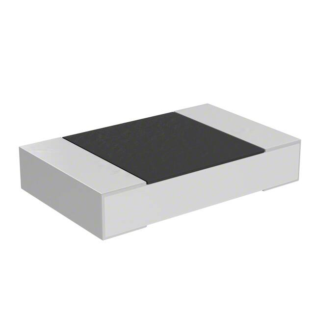


 工商网监
湘ICP备2023018690号
工商网监
湘ICP备2023018690号
