RAMK060
www.vishay.com
Vishay MCB
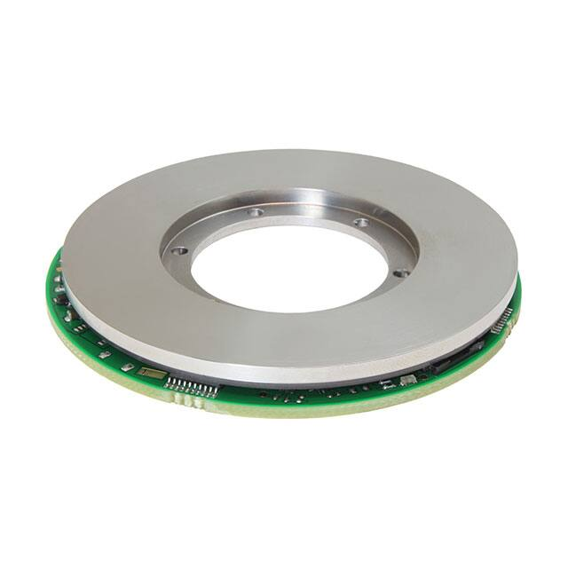
Rotational Absolute Magnetic Kit Encoder Version 60 mm
HP Position Sensor Version 2.1
FEATURES
• Especially dedicated to robotics applications
• High precision, high repeatability,
resolution, single or multi-turns variant
high
• Plug and play or self-calibration
• Memorization of last position before power off
• Not sensitive to external magnetic fields and temperature
• Not sensitive to moisture and pollution
LINKS TO ADDITIONAL RESOURCES
• Especially dedicated for harsh conditions (vibrations,
shocks, CEM…)
3D 3D
3D Models
Videos
• Built-in self-monitoring
• Hall effect principle
QUICK REFERENCE DATA
• Option back-up battery connector
Sensor type
ROTATIONAL, magnetic technology
Output type
Connector Würth Elektronik 687106182122
to plug a flat flex cable or
connector Hirose DF58-6P-1.2V(21) to plug
an external connector equipped of wires
Market appliance
Dimensions
• Protected design, patent EP 2711663
• Material categorization: for definitions of compliance
please see www.vishay.com/doc?99912
Industrial
Diameter 60 mm
ELECTRICAL SPECIFICATIONS
PARAMETER
Voltage power supply (on sensor connector)
5 V ± 0.25 V
≤ 180 mA
Supply current at 5 V
Standard output format
SSI
Optional output format
Biss-C or SPI
Useful electrical angle
360°
Accuracy at 25 °C
Better than 13 bits (0.044°)
Repeatability
> 16 bits
≈ 0.001° (335 872 points, ≈ 18.35 bits)
Resolution
Startup time
≤ 20 ms
Data latency time
≤ 200 μs
Maximum sampling rate
9.2 kHz
Optional multi-turn counter without external battery
For multi-turns options
16 bits counter
Memorization of the last angle value and the multi-turns counter at the power off
On request: multi-turns counter with external
backup battery (not supplied)
16 bits counter, battery: voltage 3.6 V to 5 V, Imax. 15 mA
MECHANICAL SPECIFICATIONS (All Versions)
PARAMETER
Mechanical angle
Maximum speed rotation
360°
10 000 rpm (mechanical limits)
Rotor weight
< 40 g
Stator weight
< 15 g
Revision: 09-Nov-2021
Document Number: 32579
1
For technical questions, contact: mcbprecisionpot@vishay.com
THIS DOCUMENT IS SUBJECT TO CHANGE WITHOUT NOTICE. THE PRODUCTS DESCRIBED HEREIN AND THIS DOCUMENT
ARE SUBJECT TO SPECIFIC DISCLAIMERS, SET FORTH AT www.vishay.com/doc?91000
�RAMK060
www.vishay.com
Vishay MCB
SAP PART NUMBERING GUIDELINES
TYPE
R = rotational
MODEL DESIGN SIZE TYPE FUNCTION ACCURACY RESOLUTION OUTPUT
(mm)
(BITS)
(BITS)
AM
K = kit
060
M
1
13
19
PACKAGING
OPTION
F=
SPI CCW
J=
SSI CCW
L=
Biss-C
B = box
F=
SPI CCW
B = box
661 = multi-turn
counting
J=
SSI CCW
B = box
663 = multi-turn
counting
L=
Biss-C
B = box
659 = multi-turn
counting
Note
• “Multi-turn with connection back-up battery” possible on request, please contact Vishay
ACCESSORY
Transfer adaptor (see section “Accessory on Request”)
ACCSRAMKADAPTCB067
PERFORMANCE
PARAMETER
Standard operating temperature range
-40 °C to +85 °C
Storage temperature range
-55 °C to +105 °C
≤ 80 % no condensing
Humidity
Environmental protection
Vibrations
Shocks
Magnetic protection
Coating on PCB components side
0.05 g2/Hz, 20 Hz to 2000 Hz for 1 hour along three major axis
100 g, 14 ms, ½ sine (one on each axis)
- No influence up to 3 mT (typical value) (uniform magnetic field)
- No permanent deviation greater than 0.03° if a magnet of 50 mT was in contact
with the upper metallic shape of the rotor
- No permanent deviation greater than 0.03° if a magnet of 50 mT was exposed
at 5 mm of the magnetic rubber
COMMUNICATION INTERFACES
Three protocols are possible: SSI protocol, Biss-C protocol, or SPI protocol.
Connector Types
Connector to plug a flat flex cable: output connector FCC pitch 0.5 mm, thickness 0.3 mm bottom contacts connector Würth
Elektronik 687106182122
Connector to plug an external connector equipped of wires: output connector wires connector on the PCB: Hirose
DF58-6P-1.2V(21)
• User crimp socket: Hirose DF58-6S-1.2C
• User crimp contact: Hirose DF58-2830SCF
Revision: 09-Nov-2021
Document Number: 32579
2
For technical questions, contact: mcbprecisionpot@vishay.com
THIS DOCUMENT IS SUBJECT TO CHANGE WITHOUT NOTICE. THE PRODUCTS DESCRIBED HEREIN AND THIS DOCUMENT
ARE SUBJECT TO SPECIFIC DISCLAIMERS, SET FORTH AT www.vishay.com/doc?91000
�RAMK060
www.vishay.com
Vishay MCB
Recommended FCC (customer side)
3.5 ± 0.08
2.5 ± 0.08
0.5 ± 0.05
0.29 ~ 0.34
4.0 min.
2.0 min.
0.3 ± 0.03
0.5 ± 0.08
Fig. 1 - Recommended FCC
Wires user connector
22
°
22
6
.5 °
1
31
°
Self-calibration activation
1
6
112.5
°
1 5
6 7°
15
7°
Flat flex cable user connector
12
LED indicators
Optional battery connector
Fig. 2 - User Connectors
Note
• See also last page for accessory which allows to provide a different pinning
Revision: 09-Nov-2021
Document Number: 32579
3
For technical questions, contact: mcbprecisionpot@vishay.com
THIS DOCUMENT IS SUBJECT TO CHANGE WITHOUT NOTICE. THE PRODUCTS DESCRIBED HEREIN AND THIS DOCUMENT
ARE SUBJECT TO SPECIFIC DISCLAIMERS, SET FORTH AT www.vishay.com/doc?91000
�RAMK060
www.vishay.com
Vishay MCB
SELF-MONITORING
All frame includes 3 status bits. These 3 status bits form a 3 bits word.
3 BITS STATUS WORD
BIT A1
BIT A2
MSB
Normal
operation
Temperature
overflow
Mechanical
mounting error
Cells default
0
0
0
0
0
1
0
1
BIT A3 DECIMAL
LED
VALUE STATUS
LSB
0
1
1
0
0
3
1
2
Green
INFORMATION
ACTION
PRIORITY
LEVEL
Frame without error or warning.
No action required.
-
Red
This error is set if the temperature
of the sensor is superior to +85 °C Set the environmental
or inferior to -40 °C.
temperature between
-40 °C to +85 °C .
This information is sent until
temperature is over range.
Red
This error is set when the
mechanical tolerances of the
airgap parameter are out of range.
This information is sent until power
supply turns off.
Red
This error occurs when a magnetic
cell is temporary or completely
out of order.
This error is sent at each
concerned frame.
Need
self-calibration
Self-calibration
error
1
1
0
0
0
1
4
5
Orange
Orange
To get the best performances,
a self-calibration is required.
This information is available until
power supply turns off.
This warning occurs when the
self-calibration is not ended
correctly. The factory settings
are restored.
1
(highest)
The mechanical
mounting must be
adjusted.
2
Check the sensor
integrity.
3
The self-calibration
shall be start.
4
The self-calibration
shall be restarted.
5
No action required.
6
This information is available until
power supply turns off.
Multi-turn
counter error
Internal angle
correction
Revision: 09-Nov-2021
1
1
1
1
0
1
6
7
Green
Orange
stealthily
This warning occurs when at the
power on the sensor has detected
an excessive displacement during
the power off. This warning and
the multi-turns counter are reset at
the next power on.
This warning occurs when the
sensor has performed an internal
correction error.
This warning is sent at each
concerned frame.
It is advisable to
adjust the mechanical
assembly or to
perform a selfcalibration.
7
(lowest)
Document Number: 32579
4
For technical questions, contact: mcbprecisionpot@vishay.com
THIS DOCUMENT IS SUBJECT TO CHANGE WITHOUT NOTICE. THE PRODUCTS DESCRIBED HEREIN AND THIS DOCUMENT
ARE SUBJECT TO SPECIFIC DISCLAIMERS, SET FORTH AT www.vishay.com/doc?91000
�RAMK060
www.vishay.com
Vishay MCB
SSI INTERFACE (Standard Output Format)
TABLE 1 - SSI CONNECTOR
PIN NO.
NAME
1
VCC power supply
2
CLK+
3
CLK-
4
DATA+
5
DATA-
6
GND power supply
tclk
≥ 1 μs
SSI
t = 20 μs
CLK+
Time out
CLK-
DATA+
A1
A2
A3
MSB
DATA-
0
1
2
3
4
5
6
18
19
20
LSB
P
22
23
21
Fig. 3 - SSI Chronogram
TABLE 2 - SSI PARAMETERS
PARAMETER
CLK differential interface
DATA differential interface
Output DATA
Clock frequency (tclk)
INFORMATION
RS422 according to the EIA-RS422
Binary two’s complement left aligned
100 kHz to 3 MHz
Data bit status
3
Data bits (angle value)
19
Parity bit
Time out (time between two requests)
ODD
20 μs minimum
TABLE 3 - SSI DATA BITS FORMAT
ANGLE VALUE SSI DATA BITS FORMAT
FRAME BITS (SSI CHRONOGRAM FIG. 3)
FUNCTION
Bit 0
Status bit A1
Bit 1
Status bit A2
Bit 2
Status bit A3
Bit 3
Data MSB
Bit 21
Data LSB
Bit 22
Always = 0
Bit 23
Parity
Revision: 09-Nov-2021
Document Number: 32579
5
For technical questions, contact: mcbprecisionpot@vishay.com
THIS DOCUMENT IS SUBJECT TO CHANGE WITHOUT NOTICE. THE PRODUCTS DESCRIBED HEREIN AND THIS DOCUMENT
ARE SUBJECT TO SPECIFIC DISCLAIMERS, SET FORTH AT www.vishay.com/doc?91000
�RAMK060
www.vishay.com
Vishay MCB
BISS-C INTERFACE (Optional)
TABLE 4 - BISS-C CONNECTOR
PIN NO.
NAME
1
VCC power supply
2
CLK+
3
CLK-
4
DATA+
5
DATA-
6
GND power supply
tclk
Biss-C
t = 20 µs
MA+
MAACK
SLO+
Start
CDS
SLO-
A1
A2
A3
MSB
0
1
2
3
21
LSB
CRC
MSB
22
23
CRC
LSB
24
Time out
28
Fig. 4 - Biss-C Chronogram
TABLE 5 - BISS-C PARAMETERS
PARAMETER
Biss-C configuration
CLK and data differential interface
Output DATA
Clock frequency (tclk)
INFORMATION
Point to point (multi-slave not supported)
RS422 according to the EIA-RS422
Left aligned
5 MHz maximum (3 MHz tested)
ACK
12 bits always equal to 0
Start
1 bit always equal to 1
CDS
1 bit always equal to 0
Data bit status
Data bits (angle value)
CRC
Time out (time between two requests)
3
19 (see Table 6)
6 bits inverted, P(x) = X3 + X1 + 1, (0 x 43)
20 μs minimum
TABLE 6 - BISS-C DATA BITS FORMAT
ANGLE VALUE BISS-C DATA BITS FORMAT
FRAME BITS (BISS-C CHRONOGRAM FIG. 4)
FUNCTION
Bit 0
Status bit A1
Bit 1
Status bit A2
Bit 2
Status bit A3
Bit 3
Data MSB
Bit 21
Data LSB
Bit 22
Always = 0
Bit 23
CRC MSB
Bit 28
CRC LSB
Revision: 09-Nov-2021
Document Number: 32579
6
For technical questions, contact: mcbprecisionpot@vishay.com
THIS DOCUMENT IS SUBJECT TO CHANGE WITHOUT NOTICE. THE PRODUCTS DESCRIBED HEREIN AND THIS DOCUMENT
ARE SUBJECT TO SPECIFIC DISCLAIMERS, SET FORTH AT www.vishay.com/doc?91000
�RAMK060
www.vishay.com
Vishay MCB
SPI INTERFACE (Optional)
TABLE 7 - SPI CONNECTOR
PIN NO.
NAME
1
VCC power supply
2
CLK
3
DATA
4
CS
5
NC
6
GND power supply
SPI Slave Mode
tp = 6 μs
tclk
ts = 1 μs
CPOL = 1
CPHA = 1
A1
A2
A3
MSB
Bit 0
Bit 1
Bit 2
Bit 3
Bit 20
Bit 21
LSB
P
Bit 22
Bit 23
A1
A2
A3
MSB
Fig. 5 - SPI Chronogram
TABLE 8 - SPI PARAMETERS
PARAMETER
INFORMATION
SPI configuration
Slave mode only
CLK and DATA
TTL 3.3 V or 5 V
Output DATA
Left aligned
Clock frequency (tclk)
Up to 4 MHz
ts (time to start)
1 μs minimum
Data bit status
3
Data bits (angle value)
19
Parity bit
Time out (time between two requests)
ODD
6 μs minimum
TABLE 9 - SPI DATA BITS FORMAT
ANGLE VALUE SPI DATA BITS FORMAT
FRAME BITS (SPI CHRONOGRAM FIG. 5)
FUNCTION
Bit 0
Status bit A1
Bit 1
Status bit A2
Bit 2
Status bit A3
Bit 3
Data MSB
Bit 21
Data LSB
Bit 22
Always = 0
Bit 23
Parity
Revision: 09-Nov-2021
Document Number: 32579
7
For technical questions, contact: mcbprecisionpot@vishay.com
THIS DOCUMENT IS SUBJECT TO CHANGE WITHOUT NOTICE. THE PRODUCTS DESCRIBED HEREIN AND THIS DOCUMENT
ARE SUBJECT TO SPECIFIC DISCLAIMERS, SET FORTH AT www.vishay.com/doc?91000
�RAMK060
www.vishay.com
Vishay MCB
OPTIONAL MULTI-TURNS COUNTER
First Possible Option: Counting of Turns Without Battery Backup Connector and Memorization of Last Position Before
Power Off!
In normal operation when the power is on, the counting of the turns is made in the two directions, clockwise and anticlockwise.
The maximum value of the counter is -32 768 anticlockwise turns to +32 767 clockwise turns. When the counter reaches the
maximum value of 32 767, the next counter value is set to -32 768. When it reaches the minimum value of -32 768, the next
value is set to 32 767.
The value of the turn counter is sent in the output frame in two complement. No counting during power off. When the power is
off, the last position before power cutting (value of the multi-turn counter and value of the angle) is memorized in a no volatile
memory and the encoder can accept (during power off) a movement of encoder up to ± 90° to calculate and release the new
position as soon as the power comes back.
The number of non-volatile memory in write-in cycles is unlimited.
At the power on, if the variation of the angle is superior to ± 90°, the error flag of the frame is set and the multi-turn counter is
reset at the next power on. This procedure could be used to reset the multi-turns counter.
The multi-turns counter is also reset when the sensor enter in the self-calibration mode.
Second Possible Option: Counting of Turns With Battery Backup Across Connector
After the power off, if the sensor turns, the number of revolutions are counted internally. The counting is made in the two
directions, clockwise and anticlockwise. The maximum value of the counter is -32 767 anticlockwise turns to +32 767 clockwise
turns. When the counter reaches the maximum value of 32 767, the next counter value is set to -32 768. When the counter
reaches the minimum of -32 768, the next value is set to 32 767.
During the power is off, no data is sent to the output. With the backup battery connector plugged to external battery, with low
consumption, the encoder counts the number of turns and stocks this data in memory. As soon as the power comes back, the
encoder releases the data of number of turns and continues to count in normal conditions.
The multi-turns counter is also reset when the sensor enter in the self-calibration mode.
MULTI-TURNS SSI OUTPUT FORMAT
≥ 1 μs
SSI
tclk
t = 20 μs
CLK+
Time out
CLKDATA+
A1
A2
A3
MSB
DATA-
0
1
2
3
4
LSB
MSB
18
19
20
21
29
LSB
P
38
39
Fig. 6 - SSI Multi-Turns Chronogram
TABLE 10 - SSI MULTI-TURN DATA BITS FORMAT
SSI DATA BITS FORMAT
DATA BIT
MSB
LSB
DATA BITS LENGTH
INFORMATION
Status bits
Frame bit 0
Frame bit 2
3 bits
See section “Self-Monitoring”
Multi-turns counter
Frame bit 3
Frame bit 18
16 bits
See Fig. 6
Angle value
Frame bit 19
Frame bit 37
19 bits
Parity
Frame bit 39
-
1 bit
See Table 3
Revision: 09-Nov-2021
Document Number: 32579
8
For technical questions, contact: mcbprecisionpot@vishay.com
THIS DOCUMENT IS SUBJECT TO CHANGE WITHOUT NOTICE. THE PRODUCTS DESCRIBED HEREIN AND THIS DOCUMENT
ARE SUBJECT TO SPECIFIC DISCLAIMERS, SET FORTH AT www.vishay.com/doc?91000
�RAMK060
www.vishay.com
Vishay MCB
MULTI-TURNS BISS-C OUTPUT FORMAT
tclk
Biss-C
t = 20 µs
MA+
MAACK
SLO+
CDS
Start
SLO-
A1
A2
A3
MSB
LSB
MSB
LSB
CRC
MSB
CRC
LSB
0
1
2
3
18
19
38
39
44
Time out
Fig. 7 - Biss-C Multi-Turns Chronogram
TABLE 11 - BISS-C MULTI-TURN DATA BITS FORMAT
BISS-C DATA BITS FORMAT
DATA BIT
MSB
LSB
DATA BITS LENGTH
INFORMATION
Status bits
Frame bit 0
Multi-turns counter
Frame bit 3
Frame bit 2
3 bits
See section “Self-Monitoring”
Frame bit 18
16 bits
Angle value
Frame bit 19
Frame bit 38
19 bits
See Fig. 7
CRC
Frame bit 39
Frame bit 44
6 bits
See Table 6
MULTI-TURNS SPI OUTPUT FORMAT
SPI Slave Mode
tclk
ts = 1 μs
tp = 6 μs
A1
A2
A3
MSB
LSB
Bit 0
Bit 1
Bit 2
Bit 3
Bit 18
MSB
Bit 19
LSB
P
A1
Bit 38
Bit 39
A2
A3
MSB
Fig. 8 - SPI Multi-Turns Chronogram
TABLE 12 - SPI MULTI-TURN DATA BITS FORMAT
SPI DATA BITS FORMAT
DATA BIT
MSB
LSB
DATA BITS LENGTH
INFORMATION
Status bits
Frame bit 0
Multi-turns counter
Frame bit 3
Frame bit 2
3 bits
See section “Self-Monitoring”
Frame bit 18
16 bits
Angle value
Frame bit 19
Frame bit 38
19 bits
See Fig. 8
Parity
Frame bit 39
-
1 bit
See Table 9
OPTIONAL BATTERY BACKUP CONNECTOR
• Header on the PCB: Hirose SMD 7 106 (666-1001-0-21)
• Crimp socket: Hirose DF58-2S-1.2C (Hirose number 666-1006-0 00)
• Crimp contact: Hirose DF58-2830SCF (Hirose number 666-1011-0 00)
Revision: 09-Nov-2021
Document Number: 32579
9
For technical questions, contact: mcbprecisionpot@vishay.com
THIS DOCUMENT IS SUBJECT TO CHANGE WITHOUT NOTICE. THE PRODUCTS DESCRIBED HEREIN AND THIS DOCUMENT
ARE SUBJECT TO SPECIFIC DISCLAIMERS, SET FORTH AT www.vishay.com/doc?91000
�RAMK060
www.vishay.com
Vishay MCB
MOUNTING INFORMATION (All Versions)
SENSOR DIMENSIONS
Data output connector
4 x 90°
Ø 47.5
A
A
4 x Ø 1.8 ± 0.1
Ø 0.1 CZ C D
Stator
A-A
Ø 57 ± 0.1 E
Ø 34.9 ± 0.1 E
Ø 0.05 B
Ø 0.05 B
Ø 0.05 B
Ø 32.5 ± 0.1 E
Ø 25 + 0.013
0
Rotor
(stainless steel
alloy + magnet)
Stator
(PCB)
2.225 ± 0.1
E
B
Ø0M A
B
A
Ø 35.8 ± 0.1
E
Ø 59.9 ± 0.1
E
DETAIL B
5:1
C
D
6.5 max.
3.1 ± 0.2
1.425 ± 0.45
2.65 ± 0.2 Rep 5
Revision: 09-Nov-2021
2.7 ± 0.3
(Air-gap: 0.5 ± 0.2
for information only)
Document Number: 32579
10
For technical questions, contact: mcbprecisionpot@vishay.com
THIS DOCUMENT IS SUBJECT TO CHANGE WITHOUT NOTICE. THE PRODUCTS DESCRIBED HEREIN AND THIS DOCUMENT
ARE SUBJECT TO SPECIFIC DISCLAIMERS, SET FORTH AT www.vishay.com/doc?91000
�RAMK060
www.vishay.com
Vishay MCB
6 x Ø 2.3 ± 0.1
Ø 0.1 CZ A B
E
6 x Ø 4.8 ± 0.05
Ø 0.1 E
Ø 29.3
6x
60
°
Mechanical zero tracking
(on request)
Rotor
2:1
22
°
.5° °
22 31
15
7°
112.5°
67°
Revision: 09-Nov-2021
Document Number: 32579
11
For technical questions, contact: mcbprecisionpot@vishay.com
THIS DOCUMENT IS SUBJECT TO CHANGE WITHOUT NOTICE. THE PRODUCTS DESCRIBED HEREIN AND THIS DOCUMENT
ARE SUBJECT TO SPECIFIC DISCLAIMERS, SET FORTH AT www.vishay.com/doc?91000
�RAMK060
www.vishay.com
Vishay MCB
MOUNTING DATA AND SELF-MONITORING
After the mounting and throughout the use of the sensor, the encoder provides across the LED colors and also across data bits
of self-monitoring the status of correct mounting and of correct operation. Look at section “Self-Monitoring” and the table
“Summary” in section “Approach No. 2”, “Self-Calibration Procedure” of §1.
x1 A
Ø V ± V1
Probe
Rep 4
Holding fixture
Measure runout shaft
Rep 3
E
Rep 2
Ø W ± W1
Rep 1
E
X C
A
x2 A
Y
C
Z Rep 5
Customer interface
Customer shaft
Fig. 9 - Mounting Detail
Rep 6
Z
Beat default
(mm)
Y
Stator
Rotor
X
Stator
Rotor
Rotor axis and stator axis are the same but the reference surfaces are not parallel
Fig. 10 - Beat
APPROACH NO. 1: TOTALLY PLUG AND PLAY WITHOUT SELF-CALIBRATION
Comment: it is the case for the customer’s equipment whose mechanical tolerances are under control (requirements described
in Table 13).
TABLE 13 - RECOMMENDED DIMENSIONS AND TOLERANCES OF CUSTOMER INTERFACES
Rep 1
Customer shaft diameter for centering of the rotor (see Fig. 9)
Rep 2
Customer interface diameter for centering of the stator (see Fig. 9)
Rep 3
Diameter runout of the customer shaft for the rotor centering (see Fig. 9)
< 0.005 mm
Rep 4
Concentricity of the stator centering diameter versus shaft centering diameter (see Fig. 9)
< 0.020 mm
Rep 5
Position of the stator reference bottom surface versus rotor reference bottom surface (see Fig. 9)
Rep 6
Total beat included in the air-gap between Ref. C (rotor) and Ref. D (stator) (see Fig. 10)
Revision: 09-Nov-2021
25 mm + 0 mm / - 0.010 mm
60 mm + 0.060 mm / 0 mm
2.65 mm ± 0.1 mm
< 0.2 mm
Document Number: 32579
12
For technical questions, contact: mcbprecisionpot@vishay.com
THIS DOCUMENT IS SUBJECT TO CHANGE WITHOUT NOTICE. THE PRODUCTS DESCRIBED HEREIN AND THIS DOCUMENT
ARE SUBJECT TO SPECIFIC DISCLAIMERS, SET FORTH AT www.vishay.com/doc?91000
�RAMK060
www.vishay.com
Vishay MCB
APPROACH NO. 2: SELF-CALIBRATION
Comment: it is the case for the customer’s equipment whose mechanical tolerances are NOT under the tolerances described
in Approach No. 1, a self-calibration can be used to compensate the misalignment (= eccentricity between rotor axis and stator
axis) and the runout of the customer shaft for the rotor centering (eccentricity mounting of the rotor).
Other case where the self-calibration has to be used, it is when the sensor sets the auto-calibration flag (conditions to use the
self-calibration procedure: Table 14).
Self-Calibration Procedure
1. How to know if the encoder needs a self-calibration
a. Mount the encoder
b. Plug the connector
c. Turn-on the power supply
d. Turn the rotor (at least 360°)
e. Look at the LED color
Case 1
Case 2
Case 3
Green LED: ON
Red LED: OFF
Orange LED: OFF
The encoder is ready to be used with full performances
Green LED: OFF
Red LED: ON
Orange LED: OFF
Bad mechanical position, adjust the mechanical position
Green LED: OFF
Red LED: OFF
Orange LED: ON
Do the self-calibration
SUMMARY
LED COLOR
STATUS
ACTION
Green
Ready to use with full performances
None
Orange
The resolution and / or the accuracy might be out of specification
Do the self-calibration
Red
Bad mechanical position
Adjust the mechanical position
No light
No power
Check the power supply
Reminder: similar data are available across the output frame “status bits of self-monitoring”:
• “Normal operation” = green color
• “Need self-calibration” = orange color
• “Mechanical mounting error” = red color
2. How to do the self-calibration
a.
b.
c.
d.
e.
f.
g.
The encoder is mounted, the connector is unplug
Plug the shunt supplied by Vishay and turn-on the power supply (the red LED is blinking)
Turn the rotor with a maximum rotation speed of 10 rpm (at least 360°) (acquisition of data = the orange LED is blinking)
When the green and orange LEDs are blinking, the correction calculation is in progress
When the green LED is blinking, the correction calculation is finished
Turn off the power supply and unplug the shunt
Plug the connector, turn-on the power supply, turn the rotor (at 360°) and look at the LED color.
Green LED: ON | Red LED: OFF | Orange LED: OFF
h. The encoder is ready to be used with full performances
Note
• The procedure of self-calibration is also described in video available to ask for Vishay
Revision: 09-Nov-2021
Document Number: 32579
13
For technical questions, contact: mcbprecisionpot@vishay.com
THIS DOCUMENT IS SUBJECT TO CHANGE WITHOUT NOTICE. THE PRODUCTS DESCRIBED HEREIN AND THIS DOCUMENT
ARE SUBJECT TO SPECIFIC DISCLAIMERS, SET FORTH AT www.vishay.com/doc?91000
�RAMK060
www.vishay.com
Vishay MCB
The self-calibration is operational when the requirements are in accordance with Table 14.
TABLE 14 - RECOMMENDED DIMENSIONS AND TOLERANCES OF CUSTOMER INTERFACES TO
USE THE SELF-CALIBRATION PROCEDURE
Diameter runout of the customer shaft for the rotor centering
(included gap between customer shaft and inner rotor diameter) (see Fig. 9)
Misalignment: concentricity of the stator centering diameter versus shaft centering diameter
(included tolerances of customer holder and stator interface) (see Fig. 9)
Position of the stator reference bottom surface versus rotor reference bottom surface (see Fig. 9)
(air-gap: the condition of previous line avoids to measure the air-gap)
Total beat included in the air-gap between Ref. C (rotor) and Ref. D (stator) (see Fig. 10)
Rep 3
Rep 4
Rep 5
Rep 6
< 0.08 mm
± 0.8 mm
2.65 mm ± 0.2 mm
(air-gap = 0.5 mm ± 0.2 mm)
< 0.2 mm
Note
• Values at room temperature
• Recommended screws for the rotor: M2 ISO 4762 (stainless steel A4) with recommended torque = 0.3 Nm ± 10 % + narrow
washer M2 NFE 25514 “Z” type (stainless steel A4) thickness 0.5 mm. It is recommended to add glue on screws threads
function of environmental and use conditions
• Recommended screws for the stator: M1.6 ISO 1207 (stainless steel A4, screw head diameter ≤ 3.2 mm and screw head
height ≤ 1 mm) with recommended torque = 0.10 Nm ± 10 % + washer M1.6 DIN 125 (insulated raw material) thickness
0.3 mm. It is recommended to add glue on screws function of environmental and use conditions
OTHER INFORMATION
ATTENTION!
Observe Precautions for Handling Electrostatic
Sensitive Devices!
Do not use magnetic parts around the encoder!
WARNING: the rotor and the stator must have the same serial number!
• Do not damage the magnetic disk surface
• Do not put the disk in contact with metallic particles
• Do not use cleaning product or chemical product
ACCESSORY ON REQUEST
TRANSFER ADAPTOR TO PROVIDE A FLAT FLEX CABLE WITH DIFFERENT PINNING AT THE OUTPUT
Side connector no. 2
Compatible WR-FFC 686606050001
Side connector no. 1
Compatible WR-FFC 687606050002
1
1
7 ± 0.1
J1
J2
6
4±1
3.5 ± 0.08
Support tape
length: 8
6
28.2 ± 0.5
5±1
Distance between support tapes: 32 mm
Support tape
length: 10
50
CONNECTOR J1
CONNECTOR J2
ENCODER RAMK SIDE
CUSTOMER DEVICE SIDE
PIN NO.
SPI
SSI/Biss-C PIN NO.
SPI
SSI/Biss-C
1
VCC
VCC
1
VCC
VCC
2
CLK
CLK+
2
Not connected
Data3
MISO
CLK3
MISO
CLK4
CS
Data+
4
CLK
CLK+
5
Not connected
Data5
CS
Data+
6
GND
GND
6
GND
GND
Revision: 09-Nov-2021
CONNECTOR J1
Pin 1
Pin 2
Pin 3
Pin 4
Pin 5
Pin 6
connected to
connected to
connected to
connected to
connected to
connected to
CONNECTOR J2
Pin 1
Pin 4
Pin 3
Pin 5
Pin 2
Pin 6
Document Number: 32579
14
For technical questions, contact: mcbprecisionpot@vishay.com
THIS DOCUMENT IS SUBJECT TO CHANGE WITHOUT NOTICE. THE PRODUCTS DESCRIBED HEREIN AND THIS DOCUMENT
ARE SUBJECT TO SPECIFIC DISCLAIMERS, SET FORTH AT www.vishay.com/doc?91000
�Legal Disclaimer Notice
www.vishay.com
Vishay
Disclaimer
ALL PRODUCT, PRODUCT SPECIFICATIONS AND DATA ARE SUBJECT TO CHANGE WITHOUT NOTICE TO IMPROVE
RELIABILITY, FUNCTION OR DESIGN OR OTHERWISE.
Vishay Intertechnology, Inc., its affiliates, agents, and employees, and all persons acting on its or their behalf (collectively,
“Vishay”), disclaim any and all liability for any errors, inaccuracies or incompleteness contained in any datasheet or in any other
disclosure relating to any product.
Vishay makes no warranty, representation or guarantee regarding the suitability of the products for any particular purpose or
the continuing production of any product. To the maximum extent permitted by applicable law, Vishay disclaims (i) any and all
liability arising out of the application or use of any product, (ii) any and all liability, including without limitation special,
consequential or incidental damages, and (iii) any and all implied warranties, including warranties of fitness for particular
purpose, non-infringement and merchantability.
Statements regarding the suitability of products for certain types of applications are based on Vishay's knowledge of typical
requirements that are often placed on Vishay products in generic applications. Such statements are not binding statements
about the suitability of products for a particular application. It is the customer's responsibility to validate that a particular product
with the properties described in the product specification is suitable for use in a particular application. Parameters provided in
datasheets and / or specifications may vary in different applications and performance may vary over time. All operating
parameters, including typical parameters, must be validated for each customer application by the customer's technical experts.
Product specifications do not expand or otherwise modify Vishay's terms and conditions of purchase, including but not limited
to the warranty expressed therein.
Hyperlinks included in this datasheet may direct users to third-party websites. These links are provided as a convenience and
for informational purposes only. Inclusion of these hyperlinks does not constitute an endorsement or an approval by Vishay of
any of the products, services or opinions of the corporation, organization or individual associated with the third-party website.
Vishay disclaims any and all liability and bears no responsibility for the accuracy, legality or content of the third-party website
or for that of subsequent links.
Except as expressly indicated in writing, Vishay products are not designed for use in medical, life-saving, or life-sustaining
applications or for any other application in which the failure of the Vishay product could result in personal injury or death.
Customers using or selling Vishay products not expressly indicated for use in such applications do so at their own risk. Please
contact authorized Vishay personnel to obtain written terms and conditions regarding products designed for such applications.
No license, express or implied, by estoppel or otherwise, to any intellectual property rights is granted by this document or by
any conduct of Vishay. Product names and markings noted herein may be trademarks of their respective owners.
© 2021 VISHAY INTERTECHNOLOGY, INC. ALL RIGHTS RESERVED
Revision: 09-Jul-2021
1
Document Number: 91000
�