RSSD
www.vishay.com
Vishay Sfernice
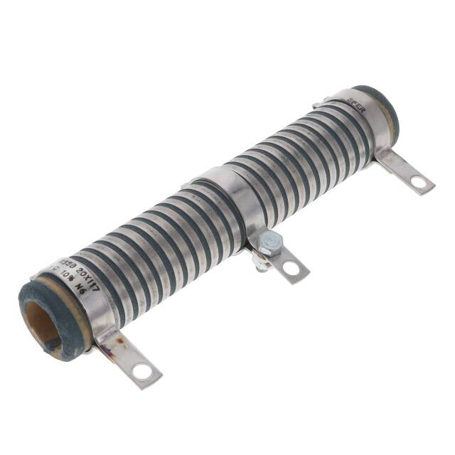
Wirewound Resistor, Industrial High Power, Vitreous Tubular,
Adjustable, Low Values 0.12 Ω to 560 Ω
FEATURES
• High power rating: 16 W to 600 W at 25 °C
• Heavy overloads 10 Pn 5 s ≤ 1 %
• Low ohmic values 0.10 Ω available
• High long term stability drift < 1.5 % after 1000 h
• Excellent withstanding of thermal shock
• Mechanical strength
• Fire proof
• Material categorization: for definitions of compliance
please see www.vishay.com/doc?99912
LINKS TO ADDITIONAL RESOURCES
3D 3D
3D Models
RSSD medium and high power resistors are noted for their ability to withstand heavy transient and severe shock and vibration
conditions. They complement the ohmic range of Vishay styles RW, RWST and RA in the low value area, and can be tapped by
means of adjustable collars. Standard RSSD resistors have a single adjustable collar.
NF F 16101, 10/1988 and 16102, 04/1992: Not applicable (our parts are made of metallic and refractory materials).
DIMENSIONS in millimeters
SCREWED STAINLESS STEEL 304 L COLLARS “CS” TYPE 1
WELDED STAINLESS STEEL 304 L COLLARS “AN” TYPE 1
Type 1 Type 2
Solded Screwed
ØC
ØC
A
Z
F
F
A
ØC
J
P
R
ØB
D
K
P
E
ØB
26
G
H
ØQ
M
15
L
SCREWED STAINLESS STEEL 304 L COLLARS “CS” TYPE 2
ØC
A
J
23
K
ØB
58
G
H
M
15
L
RSSD
SERIES
ØB
MAX.
ØC
MIN.
D
E
34
10
4.1
27 ± 2
50
11.5
5
40 ± 2
70
14.5
6.7
AN type1
94
18
AN type1
117
22
CONNECTION
A±2
8 x 34
AN type1
10 x 50
AN type1
13 x 70
AN type1 CS (1)
16 x 94
20 x 117
Z
APPROX.
AVERAGE
UNIT
WEIGHT IN g
16 ± 0.5
1
10
18 ± 0.5
1.5
22
4.2
20 ± 0.5
3.5
38
38 ± 1
4.2
21 ± 0.5
4
55
42 ± 1
4.2
24 ± 0.7
5
80
F + 0.5
+0
P
ØQ
R
20 ± 0.5
5
28 ± 1
3.2
22 ± 0.5
6.35
31 ± 1
4.2
56 ± 2
24 ± 0.5
6.35
34 ± 1
9.2
78 ± 2
26.5 ± 0.5
6.35
12.6
98 ± 2
31 ± 0.7
6.35
Note
(1) CS connections on request
Revision: 17-Dec-2021
Document Number: 50020
1
For technical questions, contact: sferfixedresistors@vishay.com
THIS DOCUMENT IS SUBJECT TO CHANGE WITHOUT NOTICE. THE PRODUCTS DESCRIBED HEREIN AND THIS DOCUMENT
ARE SUBJECT TO SPECIFIC DISCLAIMERS, SET FORTH AT www.vishay.com/doc?91000
�RSSD
www.vishay.com
Vishay Sfernice
DIMENSIONS in millimeters
RSSD
SERIES
25 x 138
25 x 168
30 x 250
40 x 370
50 x 373
CONNECTIONS
AN type1
AN type1
AN type1
AN type2
AN type2
RSSD
SERIES
25 x 138
25 x 168
30 x 250
40 x 370
50 x 373
cs type1
cs type1
cs type1
cs type2
cs type2
CONNECTIONS
AN type1
AN type1
AN type1
AN type2
AN type2
ØC
MIN.
16.4
16.4
21.3
22.3
27.1
D
E
138
168
250
370
373
ØB
MAX.
27
27
32
43
53
117 ± 2
147 ± 2
227 ± 2.5
332 ± 3
332 ± 3
K
L ± 0.5
M ± 0.5
27 ± 1
27 ± 1
30 ± 1
45 ± 1
51 ± 1.5
6.5
6.5
9
9
9
24
24
25
30
30
A±2
cs type1
cs type1
cs type1
cs type2
cs type2
33.5 ± 1
33.5 ± 1
36 ± 1
57 ± 1.5
63 ± 1.5
F + 0.5
+0
9
9
13
18
18
G-4
-0
199
229
317
432
432
P
ØQ
R
Z
APPROX.
51 ± 1.5
51 ± 1.5
55 ± 1.5
81.5 max.
92.5 max.
5.7
5.7
5.7
9.2
9.2
28.5 ± 1
28.5 ± 1
31± 1
45 ± 1.5
51 ± 1.5
6
6
5
10
11.5
H-4
J
-0
169
50 ± 1.5
199
50 ± 1.5
287
60 ± 1.5
405
69 max.
405
80 max.
AVERAGE UNIT
WEIGHT IN g
AN
CS
90
135
115
160
240
290
845
925
1270
1350
STANDARD ELECTRICAL SPECIFICATIONS
MODEL
SIZE
RESISTANCE
RANGE
Ω
RATED POWER
P25 °C
W
TOLERANCE
±%
RSSD 8 x 34
0834
0.12 to 10
16
5, 10 , 20
RSSD 10 x 50
1050
0.12 to 22
25
5, 10 , 20
RSSD 13 x 70
1370
0.12 to 43
42
5, 10 , 20
RSSD 16 x 94
1694
0.33 to 75
70
5, 10 , 20
RSSD 20 x 117
20117
0.22 to 100
100
5, 10 , 20
RSSD 25 x 138
25138
0.10 to 150
140
5, 10 , 20
RSSD 25 x 168
25168
0.12 to 220
200
5, 10 , 20
RSSD 30 x 250
30250
0.22 to 360
280
5, 10 , 20
RSSD 40 x 370
40370
0.47 to 470
450
5, 10 , 20
RSSD 50 x 373
50373
0.68 to 560
600
5, 10 , 20
MECHANICAL SPECIFICATIONS
Mechanical Protection
Resistive Element
Connections
Average Unit Weight
Vishay Sfernice special cement
Climatic Category
Resistance Range
Nickel alloy wire
AN collars
CS supporting collars
10 g to 1350 g
ENVIRONMENTAL SPECIFICATIONS
Temperature Range
TECHNICAL SPECIFICATIONS
0.12 Ω to 560 Ω
(E12 series)
Standard Tolerance
R ≥ 10 Ω ± 5 % (1)
1 Ω ≤ R < 10 Ω ± 10 %
0.1 Ω ≤ R < 1 Ω ± 20 %
Power Rating
14 W to 600 W at 25 °C
Note
(1) 10 % for RSSD 8 x 34 only
-55 °C, +450 °C
-55 °C / +200 °C / 56 days
PERFORMANCE
TESTS
CONDITIONS
REQUIREMENTS
TYPICAL VALUES AND DRIFTS
Short Time Overload
10 Pr during 5 s
2%
1%
Climatic Sequence
-55 °C, +200 °C
5 cycles
3%
1%
Load at 100 % Pr
followed by cold -55 °C / 15
2%
or 0.05 Ω
1%
90 / 30 cycle
1000 h at Pr at +25 °C
5%
5%
Thermal Shock
Load Life
Revision: 17-Dec-2021
Document Number: 50020
2
For technical questions, contact: sferfixedresistors@vishay.com
THIS DOCUMENT IS SUBJECT TO CHANGE WITHOUT NOTICE. THE PRODUCTS DESCRIBED HEREIN AND THIS DOCUMENT
ARE SUBJECT TO SPECIFIC DISCLAIMERS, SET FORTH AT www.vishay.com/doc?91000
�RSSD
www.vishay.com
Vishay Sfernice
SPECIAL FEATURES
RSSD TYPE
8 x 34
10 x 50
13 x 70
16 x 94
Continuous
16 W
25 W
42 W
70 W
100 W
140 W
200 W
280 W
450 W
600 W
Reduced
14 W
22 W
38 W
62 W
90 W
125 W
170 W
240 W
360 W
450 W
0.12 Ω
10 Ω
0.12 Ω
22 Ω
0.12 Ω
43 Ω
0.33 Ω
75 Ω
0.22 Ω
100 Ω
0.10 Ω
150 Ω
0.12 Ω
220 Ω
0.22 Ω
360 Ω
0.47 Ω
470 Ω
0.68 Ω
560 Ω
Maximum Number
of Additional Tapping
0
1
1
1
1
1
2
2
4
4
Reduction % of Ohmic
Value by Tapping
23
21
14
11
10
8
6.5
6
5.7
5.7
Power Rating
at 25 °C
Resistance Ohmic Range
(E12, E24 Series)
with 1 Tapping
20 x 117 25 x 138 25 x 168 30 x 250 40 x 370 50 x 373
ADDITIONAL TAPPINGS
Are supplied with their adjustable collars fastened but not set to any specific value. Please note that, on request, all tappings
can be adjusted by Vishay Sfernice. For adjustment purposes we would need to be advised of the ohmic values, and tolerances
of the sections in successive order in addition to their sum Rn.
The permissible maximum value for an adjustment should take into account the possible negative tolerance of Rn.
Please consult Vishay Sfernice regarding the acceptable
tolerance.
RECOMMENDATIONS FOR USE
Maximum Current Strength:
The ohmic value and the power decrease as the connections are brought together. To avoid overload, the maximum current
strength that is permissible for Rn should never be exceeded:
Imax. = P r ⁄ R n
POWER RATING
TEMPERATURE RISE
80
60
40
0
0
100
200
300
400
300
200
100
0
450
D8
x3
4
SD
10
x5
RS
0
SD
13
x
RS
70
SD
1
RS 6 x 9
SD
4
20
RS
x1
SD
17
RS
2
SD 5 x
13
2
5
8
RS
SD x 16
8
30
x
RS
25
SD
0
40
RS
x
SD
37
0
50
x3
73
400
RS
S
RATED POWER IN %
100
RS
HOT SPOT TEMPERATURE IN °C
120
AMBIENT TEMPERATURE IN °C
10
100
1000
RATED POWER IN W
MARKING
Vishay Sfernice trademark, model, style, nominal resistance (in Ω), tolerance (in %), manufacturing date.
ORDERING INFORMATION
RSSD
10 × 50
MODEL
STYLE
SPECIAL
DESIGN
Method No
Optional
Revision: 17-Dec-2021
AN
10U
5%
BA25
e
CONNECTIONS
OHMIC VALUE
TOLERANCE
PACKAGING
LEAD
(Pb)-FREE
Custom items are
subject to extra-charge and
min. order.
Please see price list.
Document Number: 50020
3
For technical questions, contact: sferfixedresistors@vishay.com
THIS DOCUMENT IS SUBJECT TO CHANGE WITHOUT NOTICE. THE PRODUCTS DESCRIBED HEREIN AND THIS DOCUMENT
ARE SUBJECT TO SPECIFIC DISCLAIMERS, SET FORTH AT www.vishay.com/doc?91000
�RSSD
www.vishay.com
Vishay Sfernice
GLOBAL PART NUMBER INFORMATION
R
S
S
GLOBAL
MODEL
RSSD
D
2
5
1
3
8
A
1
5
R
0
J
B
1
5
SIZE
LEADS
OHMIC VALUE
TOLERANCE
PACKAGING
SPECIAL
08 x 34
10 x 50
13 x 70
16 x 94
20 x 117
25 x 138
25 x 168
30 x 250
40 x 370
50 x 373
A = AN
B=B
C = CS
F = faston
The three first digits are
significant figures and the last
digit specifies the number of
zeros to follow.
R designates decimal point.
J=5%
K = 10 %
M = 20 %
Standard
packaging:
BXX = box,
XXPCS
(fixed qty
depending on
size)
As applicable.
Example: CB4
4700 = 470 Ω
48R5 = 48.5 Ω
R010 = 0.01 Ω
...
No standard
packaging:
B00 = box,
qty open
RELATED DOCUMENTS
APPLICATION NOTES
Packaging Information
www.vishay.com/doc?50033
Accessories
www.vishay.com/doc?50021
Revision: 17-Dec-2021
Document Number: 50020
4
For technical questions, contact: sferfixedresistors@vishay.com
THIS DOCUMENT IS SUBJECT TO CHANGE WITHOUT NOTICE. THE PRODUCTS DESCRIBED HEREIN AND THIS DOCUMENT
ARE SUBJECT TO SPECIFIC DISCLAIMERS, SET FORTH AT www.vishay.com/doc?91000
�Legal Disclaimer Notice
www.vishay.com
Vishay
Disclaimer
ALL PRODUCT, PRODUCT SPECIFICATIONS AND DATA ARE SUBJECT TO CHANGE WITHOUT NOTICE TO IMPROVE
RELIABILITY, FUNCTION OR DESIGN OR OTHERWISE.
Vishay Intertechnology, Inc., its affiliates, agents, and employees, and all persons acting on its or their behalf (collectively,
“Vishay”), disclaim any and all liability for any errors, inaccuracies or incompleteness contained in any datasheet or in any other
disclosure relating to any product.
Vishay makes no warranty, representation or guarantee regarding the suitability of the products for any particular purpose or
the continuing production of any product. To the maximum extent permitted by applicable law, Vishay disclaims (i) any and all
liability arising out of the application or use of any product, (ii) any and all liability, including without limitation special,
consequential or incidental damages, and (iii) any and all implied warranties, including warranties of fitness for particular
purpose, non-infringement and merchantability.
Statements regarding the suitability of products for certain types of applications are based on Vishay's knowledge of typical
requirements that are often placed on Vishay products in generic applications. Such statements are not binding statements
about the suitability of products for a particular application. It is the customer's responsibility to validate that a particular product
with the properties described in the product specification is suitable for use in a particular application. Parameters provided in
datasheets and / or specifications may vary in different applications and performance may vary over time. All operating
parameters, including typical parameters, must be validated for each customer application by the customer's technical experts.
Product specifications do not expand or otherwise modify Vishay's terms and conditions of purchase, including but not limited
to the warranty expressed therein.
Hyperlinks included in this datasheet may direct users to third-party websites. These links are provided as a convenience and
for informational purposes only. Inclusion of these hyperlinks does not constitute an endorsement or an approval by Vishay of
any of the products, services or opinions of the corporation, organization or individual associated with the third-party website.
Vishay disclaims any and all liability and bears no responsibility for the accuracy, legality or content of the third-party website
or for that of subsequent links.
Except as expressly indicated in writing, Vishay products are not designed for use in medical, life-saving, or life-sustaining
applications or for any other application in which the failure of the Vishay product could result in personal injury or death.
Customers using or selling Vishay products not expressly indicated for use in such applications do so at their own risk. Please
contact authorized Vishay personnel to obtain written terms and conditions regarding products designed for such applications.
No license, express or implied, by estoppel or otherwise, to any intellectual property rights is granted by this document or by
any conduct of Vishay. Product names and markings noted herein may be trademarks of their respective owners.
© 2022 VISHAY INTERTECHNOLOGY, INC. ALL RIGHTS RESERVED
Revision: 01-Jan-2022
1
Document Number: 91000
�