S Series
Vishay BCcomponents
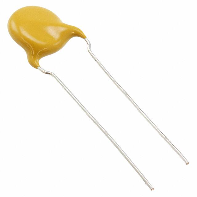
Ceramic Disc Capacitors
Class 1, 3 kVDC
FEATURES
D
D
• Low losses
• High stability
• High capacitance in small size
Tangent
line
SH
Tangent
line
SH
• Kinked (preferred) or straight leads
• Compliant to RoHS directive 2002/095/EC
APPLICATIONS
• DC high voltage
• Pulse high voltage
• LCD backlight inverter
F
F
DESIGN
Capacitors with 7.5 mm (0.30") and 10 mm (0.40") lead spacing
QUICK REFERENCE DATA
DESCRIPTION
CLASS 1 (C0G)
Voltage (VDC)
3000
Min. Capacitance (pF)
2
Max. Capacitance (pF)
220
Mounting
The capacitors consist of a ceramic disc both sides of which
are silver-plated. Connection leads are made of tinned
copper having a diameter of 0.6 mm or 0.8 mm.
The capacitors may be supplied with kinked or straight
leads with a lead spacing of 7.5 mm (0.30") or 10 mm (0.40")
and a lead length from 4 mm to 30 mm. The standard
tolerance on capacitance is ± 5 % or ± 10 % for class 1
capacitors. Encapsulation is made of gold-colored
epoxy-resin, flammable resistant in accordance with
“UL 94 V-0”
Through hole
CAPACITANCE RANGE
MARKING
Class 1, at 1 MHz, 1.2 VRMS; 2 pF to 220 pF
Straight and kinked leaded versions are gold coloured
Marking indicates capacitance value and tolerance in
accordance with ”EIA 198”, and voltage.
RATED DC VOLTAGE
OPERATING TEMPERATURE RANGE
DIELECTRIC STRENGTH
Class 1, C0G; U2J, U2M, - 55 °C to + 125 °C
According to IEC 384-8, 1.5 x UR + 500 VDC (5 kVDC)
TEMPERATURE COEFFICIENTS
INSULATION RESISTANCE AT 500 VDC
Class 1, C0G
≥ 10 000 MΩ
SECTIONAL SPECIFICATIONS
TOLERANCE ON CAPACITANCE
Class 1, IEC 60384-8,
EIA 198
± 5 %; ± 10 %;
CLIMATIC CATEGORY
DISSIPATION FACTOR
Class 1, C0G; U2J, U2M, 55/125/21
3 kV
Other tolerances available on request
C ≤ 5 pF, 0.55 % max.
10 pF ≤ C < 33 pF, 20 x (150/C + 7) x 10-4
C ≥ 33 pF; 0.20 % max.
www.vishay.com
72
For technical questions, contact: CDC@vishay.com
Document Number: 28541
Revision: 07-Jan-10
�S Series
Ceramic Disc Capacitors
Class 1, 3 kVDC
Vishay BCcomponents
ORDERING INFORMATION 3 kVDC, KINKED
C
(pF)
TOL.
(%)
DMAX.
(mm)
LEAD SPACING
(mm)
SH/DRMAX. (1)
(mm)
CLEAR TEXT CODE
13TH DIGIT:
T = REEL; U = AMMO; 3 = BULK
CLASS 1 C0G
2
3
4.9
S209C25C0KR6.K7R
± 0.25
S309C25C0JR6.K7R
± 0.50
S499D25C0HR6.K7R
10
S100J25U2JR6.K7R
6.5
15
S150J25U2JR6.K7R
22
S220J25U2MR6.K7R
33
47
68
7.5
7.5
4.0
S330J25U2MR6.K7R
S470J29U2MR6.K7R
8
S680J31U2MR6.K7R
9
S101J35U2MR6.K7R
120
10
S121J39U2MR6.K7R
150
10.5
S151J41U2MR6.K7R
±5
100
180
S181J49U2MR6.K7R
12.5
220
S221J49U2MR6.K7R
Notes
(1) SH = Seated height
• Maximum thickness 5.0 mm
• Refer to outward kinked leads. Other styles available on request (straight or inline kinked leads).
PACKAGING
PACKAGING TYPE
SIZE CODE
LEAD SPACE
(mm)
VOLTAGE (VDC)
SPQ
BOX DIMENSIONS
LxWxH
1000
Bulk
(long lead
L ≥ 25.4 mm)
1000
20 to 47
1000
53 to 45
≥ 7.5
3 kV
245 x 120 x 65
500
84 to 96
250
Tape and reel
≤ 47
1000
370 x 370 x 60
Ammopack
≤ 47
1500
360 x 330 x 55
Note
• The capacitors are supplied in bulk packaging (cardboard boxes), in tape on reel or in ammopack
Document Number: 28541
Revision: 07-Jan-10
For technical questions, contact: CDC@vishay.com
www.vishay.com
73
�S Series
Ceramic Disc Capacitors
Class 1, 3 kVDC
Vishay BCcomponents
P2
D
Δh
P
ΔP
Δh
ΔP
H1
W2
H0
L
W1
W0 W
A
e
Direction of unreeling
Ød
P1
D0
P0
t1
t
detail A
Kinked capacitors on tape, lead spacing 5.0 mm (0.2")
DIMENSIONS OF TAPE
DIMENSIONS (mm)
SYMBOL
PARAMETER
D
Body diameter
14.0 max.
-
d
Lead diameter
0.6
± 0.05
P
NOMINAL
TOLERANCE
Pitch between capacitors
15
± 1.0
P0 (1)
Feed-hole pitch
15
± 0.3
ΔP
Plane deviation
1.0 max.
-
P1
(2)
Feed-hole center to lead center
3.75
± 0.7
Feed-hole center to component center
7.5
± 1.3
F
Lead spacing
7.5
-1.5
Δh
Component alignment
0
± 1.0
W
Tape width
18.0
1.0
- 0.5
W0
Hold-down tape width
5.0 min.
-
P2 (2)
W1
Hole position
9.0
0.75
- 0.5
W2
Hold-down tape margin
3.0 max.
-
H0
Height to seating plane
16.0
± 0.5
H1
Maximum component height
40.0
-
e
Lead end protrusion
1.0 max.
-
L
Maximum length of snipped lead
11.0
± 0.2
D0
Feed-hole diameter
4.0
t
Total tape thickness
0.9 max.
-
t1
Maximum thickness of tape and wires
1.5 max.
-
Notes
(1) Cumulative pitch error: ± ≤ 1 mm/20 pitches
(2) Obliquity maximum 3°
www.vishay.com
74
For technical questions, contact: CDC@vishay.com
Document Number: 28541
Revision: 07-Jan-10
�S Series
Ceramic Disc Capacitors
Class 1, 3 kVDC
Vishay BCcomponents
REEL AND TAPE DATA in millimeters
51 max.
355.6 ± 2.0
28 ± 1.5
8.0
45 max.
Reel with capacitors on tape
290
335
50
Ammopack with capacitors on tape
Document Number: 28541
Revision: 07-Jan-10
For technical questions, contact: CDC@vishay.com
www.vishay.com
75
�Legal Disclaimer Notice
www.vishay.com
Vishay
Disclaimer
ALL PRODUCT, PRODUCT SPECIFICATIONS AND DATA ARE SUBJECT TO CHANGE WITHOUT NOTICE TO IMPROVE
RELIABILITY, FUNCTION OR DESIGN OR OTHERWISE.
Vishay Intertechnology, Inc., its affiliates, agents, and employees, and all persons acting on its or their behalf (collectively,
“Vishay”), disclaim any and all liability for any errors, inaccuracies or incompleteness contained in any datasheet or in any other
disclosure relating to any product.
Vishay makes no warranty, representation or guarantee regarding the suitability of the products for any particular purpose or
the continuing production of any product. To the maximum extent permitted by applicable law, Vishay disclaims (i) any and all
liability arising out of the application or use of any product, (ii) any and all liability, including without limitation special,
consequential or incidental damages, and (iii) any and all implied warranties, including warranties of fitness for particular
purpose, non-infringement and merchantability.
Statements regarding the suitability of products for certain types of applications are based on Vishay's knowledge of typical
requirements that are often placed on Vishay products in generic applications. Such statements are not binding statements
about the suitability of products for a particular application. It is the customer's responsibility to validate that a particular product
with the properties described in the product specification is suitable for use in a particular application. Parameters provided in
datasheets and / or specifications may vary in different applications and performance may vary over time. All operating
parameters, including typical parameters, must be validated for each customer application by the customer's technical experts.
Product specifications do not expand or otherwise modify Vishay's terms and conditions of purchase, including but not limited
to the warranty expressed therein.
Hyperlinks included in this datasheet may direct users to third-party websites. These links are provided as a convenience and
for informational purposes only. Inclusion of these hyperlinks does not constitute an endorsement or an approval by Vishay of
any of the products, services or opinions of the corporation, organization or individual associated with the third-party website.
Vishay disclaims any and all liability and bears no responsibility for the accuracy, legality or content of the third-party website
or for that of subsequent links.
Except as expressly indicated in writing, Vishay products are not designed for use in medical, life-saving, or life-sustaining
applications or for any other application in which the failure of the Vishay product could result in personal injury or death.
Customers using or selling Vishay products not expressly indicated for use in such applications do so at their own risk. Please
contact authorized Vishay personnel to obtain written terms and conditions regarding products designed for such applications.
No license, express or implied, by estoppel or otherwise, to any intellectual property rights is granted by this document or by
any conduct of Vishay. Product names and markings noted herein may be trademarks of their respective owners.
© 2021 VISHAY INTERTECHNOLOGY, INC. ALL RIGHTS RESERVED
Revision: 09-Jul-2021
1
Document Number: 91000
�


 工商网监
湘ICP备2023018690号
工商网监
湘ICP备2023018690号
