Upgrade for High Shock and Vibration Performance With T16
ST
www.vishay.com
Vishay
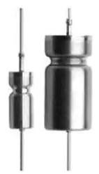
SuperTan® Wet Tantalum Capacitors With Hermetic Seal
FEATURES
•
•
•
•
•
•
•
•
LINKS TO ADDITIONAL RESOURCES
3D 3D
Very high capacitance
10 μF to 2200 μF
25 VDC to 125 VDC
Very low ESR
High ripple current
All tantalum case
Hermetically sealed
Low DCL
Available
Available
• Axial through-hole terminations: standard tin / lead (Sn / Pb),
100 % tin (RoHS-compliant) available
3D Models
• Material categorization: for definitions of compliance
please see www.vishay.com/doc?99912
Vishay ST represents a major breakthrough in wet tantalum
capacitor technology. Its unique cathode system provides
the highest capacitance per unit volume. The design
facilitates a doubling of capacitance, lower ESR and higher
ripple current rating compared with conventional wet
tantalum products. Moreover, the ST has the capacitance
stability of a solid tantalum capacitor and there are no circuit
impedance restrictions.
Note
* This datasheet provides information about parts that are
RoHS-compliant and / or parts that are non RoHS-compliant. For
example, parts with lead (Pb) terminations are not RoHS-compliant.
Please see the information / tables in this datasheet for details
APPLICATION NOTES
a. No continuous reverse voltage permissible.
b. The peak of the applied AC ripple and the applied DC
voltage must not exceed the DC voltage rating of the
capacitor.
c. Ripple current ratings by part number at 85 °C and
40 kHz are included in the table. Ripple current correction
factors for other temperatures and frequencies are given
on the next page.
d. Transient reverse voltage surges are acceptable under
the following conditions:
the peak reverse voltage does not exceed 1.5 V and the
peak current times the duration of the reverse transient
does not exceed 0.05 As. In addition, the repetition
frequency of the reverse voltage surge is less than 10 Hz.
The ST is housed in an all tantalum, hermetically sealed case
and is manufactured to withstand hazardous environments.
The ST is used widely in the defense and aerospace
industries and whenever there is a space problem.
PERFORMANCE CHARACTERISTICS
Operating Temperature: -55 °C to +85 °C
(to +125 °C with voltage derating)
Capacitance Tolerance: at 120 Hz, +25 °C.
± 20 % standard. ± 10 % available as special.
ORDERING INFORMATION
ST
220
100
T4
M
I (1)
E3 (2)
TYPE
CAPACITANCE
μF
DC VOLTAGE
RATING AT +85 °C
CASE
CODE
CAPACITANCE
TOLERANCE
INSULATING
SLEEVE
TERMINATION AND PACKAGING
M = ± 20 %
K = ± 10 %
I = insulated
X = uninsulated
E3 = 100 % tin termination
(RoHS-compliant)
Blank = SnPb termination
(standard design)
J = SMD, outside bend, tin / lead
K = SMD, outside bend, 100 % tin
L = SMD, inside bend, tin / lead
M = SMD, inside bend, 100 % tin
Notes
• Packaging: The use of formed plastic trays for packing bulk components is standard. Tape and reel cannot be used due to unit weight
(1) Sleeve on J, K, L, M terminations shall be Kapton only
(2) J, K, L, M are available in T4. For all other case sizes, check with marketing
Revision: 12-May-2022
Document Number: 43000
1
For technical questions, contact: tantalum@vishay.com
THIS DOCUMENT IS SUBJECT TO CHANGE WITHOUT NOTICE. THE PRODUCTS DESCRIBED HEREIN AND THIS DOCUMENT
ARE SUBJECT TO SPECIFIC DISCLAIMERS, SET FORTH AT www.vishay.com/doc?91000
�Upgrade for High Shock and Vibration Performance With T16
ST
www.vishay.com
Vishay
AXIAL DIMENSIONS in inches [millimeters]
Terminal welded
to case
0.0253 ± 0.002 [0.64 ± 0.05] dia.
(no. 22 AWG) tinned nickel leads
solderable and weldable
0.250 [6.35]
MAX.
0.094 [2.38]
MAX.
L1
E
Terminal location
within 0.031 of center
“D” DIA.
E
CASE CODE
D ± 0.016 [0.41]
MAX. INSULATED
(DIA.)
L1 + 0.031 / - 0.016 [+ 0.79 / - 0.41]
UNINSULATED
E ± 0.250 [6.3] MAX.
T1
0.188 [4.78]
0.219 [5.56]
0.453 [11.51]
1.500 [38.10]
T2
0.281 [7.14]
0.312 [7.92]
0.641 [16.28]
2.250 [57.15]
L2
0.281 [7.14]
0.312 [7.92]
1.008 [25.60]
2.250 [57.15]
T3
0.375 [9.52]
0.406 [10.31]
0.766 [19.46]
2.250 [57.15]
T4
0.375 [9.52]
0.406 [10.31]
1.062 [26.97]
2.250 [57.15]
Notes
• Material at egress is tantalum
• Insulation sleeving will lap over the ends of the capacitor case
• Approx. weight:
T1: 2.3 g, T2: 5.7 g,
T3: 9.4 g, T4: 14.8 g
SMD PRODUCT DIMENSIONS in inches [millimeters]
Styles J, K
Styles L, M
Solder type
Term. code
100 % tin (RoHS-compliant)
J
K
SnPb
Solder type
Term. code
100 % tin (RoHS-compliant)
L
M
SnPb
L
L
L1
ØD
H2
H
H2
H
Tl x 2
Tw x 2
L1
ØD
Tl x 2
Tw x 2
A
CASE CODE
TYPE ST
ST
D
T4
B
A
(max.)
B
(max.)
Tl
(max.)
H
(max.)
Tw ± 0.005
H2
(max.)
L
(max.)
L1
D
(max.)
1.432
[36.4]
1.140
[29.0]
0.157
[4.0]
0.295
[7.5]
0.331
[8.4]
0.492
[12.5]
1.343
[34.1]
1.062 + 0.031 / - 0.016
[26.97 + 0.79 / - 0.41]
0.397
[10.1]
Revision: 12-May-2022
Document Number: 43000
2
For technical questions, contact: tantalum@vishay.com
THIS DOCUMENT IS SUBJECT TO CHANGE WITHOUT NOTICE. THE PRODUCTS DESCRIBED HEREIN AND THIS DOCUMENT
ARE SUBJECT TO SPECIFIC DISCLAIMERS, SET FORTH AT www.vishay.com/doc?91000
�Upgrade for High Shock and Vibration Performance With T16
ST
www.vishay.com
Vishay
STANDARD RATINGS
CAPACITANCE
AT 25 °C
AND 120 Hz
(μF)
MAX. DCL AT
CASE
CODE
MAX.
ESR
120 Hz
(Ω)
+25 °C
(μA)
120
560
1100
1200
1800
2200
T1
T2
L2
T3
T4
T4
1.3
0.83
0.5
0.65
0.5
0.5
1
2
3
5
6
10
100
470
680
950
1000
1500
T1
T2
T4
L2
T3
T4
1.3
0.85
0.7
0.5
0.7
0.6
1
2
5
5
7
12
68
220
450
470
680
T1
T2
L2
T3
T4
1.5
0.9
0.6
0.75
0.7
1
2
3
3
5
47
150
370
390
560
1000
T1
T2
L2
T3
T4
T4
2.0
1.1
0.6
0.9
0.8
1.0
1
2
3
3
5
12
33
110
250
330
470
T1
T2
L2
T3
T4
2.5
1.3
0.8
1.0
0.9
1
2
5
3
5
15
68
120
150
220
T1
T2
L2
T3
T4
3.5
2.1
1.0
1.6
1.2
1
2
3
3
5
10
47
90
82
100
150
T1
T2
L2
T3
T3
T4
5.5
2.3
1.3
1.8
1.8
1.6
1
2
5
3
3
5
MAX. IMP.
AT -55 °C
AND 120 Hz
(Ω)
MAX. CAPACITANCE
CHANGE AT
+85 °C /
-55 °C
+85 °C
+125 °C
(%)
(%)
(μA)
25 VDC AT 85 °C; 15 VDC AT 125 °C
5
25
-42
+8
10
12
-65
+10
25
7
-60
+20
20
7
-70
+12
25
7
-72
+12
80
10
-90
+30
30 VDC AT 85 °C; 20 VDC AT 125 °C
5
25
-38
+8
10
15
-65
+10
40
8
-58
+10
30
7
-55
+18
25
7
-70
+10
35
6
-72
+10
50 VDC AT 85 °C; 30 VDC AT 125 °C
5
35
-25
+8
10
17.5
-50
+8
25
7.5
-45
+12
25
10
-45
+8
40
8
-58
+10
60 VDC AT 85 °C; 40 VDC AT 125 °C
5
44
-25
+8
10
20
-40
+8
25
9
-33
+9
25
15
-45
+8
40
10
-58
+8
90
20
-90
+30
75 VDC AT 85 °C; 50 VDC AT 125 °C
5
66
-25
+5
10
24
-35
+6
30
12
-30
+6
30
12
-45
+6
50
12
-50
+6
+125 °C
(%)
AC RIPPLE
85 °C
40 kHz
(mA)
RMS
PART NUMBER (1)
+12
+15
+45
+18
+20
+50
1250
2100
3200
2600
3100
3200
ST120-25T1MI
ST560-25T2MI
ST1100-25L2MI
ST1200-25T3MI
ST1800-25T4MI
ST2200-25T4MI
+12
+18
+20
+35
+18
+20
1200
1800
2750
3200
2500
3000
ST100-30TMI
ST470-30T2MI
ST680-30T4MI
ST950-30L2MI
ST1000-30T3MI
ST1500-30T4MI
+15
+15
+30
+15
+20
1050
1800
2900
2100
2750
ST68-50T1MI
ST220-50T2MI
ST450-50L2MI
ST470-50T3MI
ST680-50T4MI
+12
+15
+20
+15
+15
+50
1050
1800
2900
2100
2750
3200
ST47-60T1MI
ST150-60T2MI
ST370-60L2MI
ST390-60T3MI
ST560-60T4MI
ST1000-60T4MI
+9
+10
+15
+10
+10
1050
1650
2500
2100
2750
ST33-75T1MI
ST110-75T2MI
ST250-75L2MI
ST330-75T3MI
ST470-75T4MI
+10
+12
+12
+12
+12
1050
1650
2200
2100
2750
ST15-100T1MI
ST68-100T2MI
ST120-100L2MI
ST150-100T3MI
ST220-100T4MI
+10
+12
+15
+12
+12
+12
1050
1650
2000
1950
2100
2750
ST10-125T1MI
ST47-125T2MI
ST90-125L2MI
ST82-125T3MI
ST100-125T3MI
ST150-125T4MI
100 VDC AT 85 °C; 65 VDC AT 125 °C
5
125
-18
+3
10
37
-30
+4
25
20.5
-30
+4
25
22
-35
+6
50
15
-40
+6
125 VDC AT 85 °C; 85 VDC AT 125 °C
5
175
-15
+3
10
47
-25
+5
25
25
-22
+4
25
40
-35
+5
25
35
-35
+5
50
20
-35
+6
Note
(1) Part numbers shown are for units with ± 20 % capacitance tolerance and insulated capacitors.
For units with ± 10 % capacitance tolerance change the letter “M” to “K”.
For units without insulation, substitute “X” with “I” at the end of the part number.
For RoHS-compliant add the “E3” for suffix
Revision: 12-May-2022
Document Number: 43000
3
For technical questions, contact: tantalum@vishay.com
THIS DOCUMENT IS SUBJECT TO CHANGE WITHOUT NOTICE. THE PRODUCTS DESCRIBED HEREIN AND THIS DOCUMENT
ARE SUBJECT TO SPECIFIC DISCLAIMERS, SET FORTH AT www.vishay.com/doc?91000
�Upgrade for High Shock and Vibration Performance With T16
ST
www.vishay.com
Vishay
RIPPLE CURRENT MULTIPLIERS VS. FREQUENCY, TEMPERATURE, AND APPLIES PEAK VOLTAGE
FREQUENCY
OF APPLIED
RIPPLE
CURRENT
120 Hz
800 Hz
1 kHz
10 kHz
40 kHz
100 kHz
AMBIENT STILL
≤ 55 85 105 125 ≤ 55 85 105 125 ≤ 55 85 105 125 ≤ 55 85 105 125 ≤ 55 85 105 125 ≤ 55 85 105 125
AIR TEMP. IN °C
% of
85 °C
rated
peak
voltage
100 %
0.60 0.39
-
-
0.71 0.43
-
-
0.72 0.46
-
-
0.88 0.55
-
-
1.0 0.63
-
-
1.1 0.69
-
-
90 %
0.60 0.46
-
-
0.71 0.55
-
-
0.72 0.55
-
-
0.88 0.67
-
-
1.0 0.77
-
-
1.1 0.85
-
-
80 %
0.60 0.52 0.35
-
0.71 0.62 0.42
-
0.72 0.62 0.42
-
0.88 0.76 0.52
-
1.0 0.87 0.59
-
1.1 0.96 0.65
-
70 %
0.60 0.58 0.44
-
0.71 0.69 0.52
-
0.72 0.70 0.52
-
0.88 0.85 0.64
-
1.0 0.97 0.73
-
1.1 1.07 0.80
-
66 2/3 % 0.60 0.60 0.46 0.27 0.71 0.71 0.55 0.32 0.72 0.72 0.55 0.32 0.88 0.88 0.68 0.40 1.0 1.0 0.77 0.45 1.1 1.1 0.85 0.50
TYPICAL PERFORMANCE CHARACTERISTICS OF ST CAPACITORS
ELECTRICAL CHARACTERISTICS
ITEM
PERFORMANCE CHARACTERISTICS
Operating temperature range
-55 °C to +85 °C (to +125 °C with voltage derating)
Capacitor tolerance
± 20 %, ± 10 % at 120 Hz, at +25 °C
Capacitor change by temperature
Limit per Standard Ratings table
ESR
Limit per Standard Ratings table, at +25 °C, 120 Hz
Impedance
Limit per Standard Ratings table, at -55 °C, 120 Hz
DCL (leakage current)
Limit per Standard Ratings table
AC ripple current
Limit per Standard Ratings table, at +85 °C and 40 kHz
Reverse voltage
There shall be no continuous reverse voltage. Transient reverse voltage surges are acceptable under
the following conditions:
a) The peak reverse voltage is equal to or less than 1.5 V and the product of the peak current times
the duration of the reverse transient is 0.05 As or less
b) The repetition rate of the reverse voltage surges is less than 10 Hz
Surge voltage
Surge voltage shall be in accordance with MIL-PRF-39006 and Table II of DSCC93026.
The DC rated surge voltage is the maximum voltage to which the capacitors can be subjected under
any conditions including transients and peak ripple at the highest line voltage.
The DC surge voltage is 115 % of rated DC voltage.
PERFORMANCE CHARACTERISTICS
ITEM
PERFORMANCE CHARACTERISTICS
Life testing
Capacitors shall be capable of withstanding a 2000 h life test at a temperature +85 °C at rated
voltage, or a 2000 h life test at 125 °C test at derated voltage.
After the test, the capacitors shall meet the following requirements:
a) DC leakage at 85 °C and 125 °C shall not exceed 125 % of the specified value
b) DC leakage at 25 °C shall not exceed the specified value
c) Capacitance shall be within +10 %, -20 % of initial value
d) ESR shall not exceed 200 % of the specified value
Revision: 12-May-2022
Document Number: 43000
4
For technical questions, contact: tantalum@vishay.com
THIS DOCUMENT IS SUBJECT TO CHANGE WITHOUT NOTICE. THE PRODUCTS DESCRIBED HEREIN AND THIS DOCUMENT
ARE SUBJECT TO SPECIFIC DISCLAIMERS, SET FORTH AT www.vishay.com/doc?91000
�Upgrade for High Shock and Vibration Performance With T16
ST
www.vishay.com
Vishay
ENVIRONMENTAL CHARACTERISTICS
ITEM
CONDITION
COMMENTS
Seal
MIL-PRF-39006
When the capacitors are tested as specified in MIL-PRF-39006,
there shall be no evidence of leakage.
Moisture resistance
MIL-PRF-39006
Moisture resistance shall be in accordance with MIL-PRF-39006.
Number of cycles: 10 continuous cycles
Barometric pressure
(reduced)
MIL-STD-202, method 105, condition E
Altitude 150 000 feet
MECHANICAL CHARACTERISTICS
ITEM
CONDITION
COMMENTS
Shock (specified pulse)
MIL-STD-202, method 213, condition I
(100 g)
The capacitors shall meet the requirements of MIL-PRF-39006.
Vibration, high frequency
MIL-STD-202, method 204, condition D
(20 g peak)
The capacitors shall meet the requirements of MIL-PRF-39006.
Thermal shock
MIL-STD-202, method 107, condition A
Thermal shock shall be in accordance with MIL-PRF-39006 when
tested for 30 cycles.
Solderability
MIL-STD-202, method 208,
ANSI/J-STD-002, test A
Solderability shall be in accordance with MIL-PRF-39006.
Terminal strength
MIL-STD-202, method 211
Terminal strength shall be in accordance with MIL-PRF-39006.
Resistance to solder heat
MIL-STD-202, method 210, condition C
The capacitors shall meet the requirements of MIL-PRF-39006.
Terminals
MIL-STD-1276
Terminals shall be as specified in MIL-STD-1276. The length and
diameter of the terminals shall be as specified in Dimensions table.
All terminals shall be permanently secured internally and
externally, as applicable. All external joints shall be welded.
Marking
MIL-STD-1285
Marking of capacitors conforms to method I of MIL-STD-1285 and
include capacitance (in μF), capacitance tolerance letter, rated
voltage, date code, lot symbol and Vishay trademark.
SELECTOR GUIDES
Tantalum Selector Guide
www.vishay.com/doc?49054
Parameter Comparison Guide
www.vishay.com/doc?42088
Revision: 12-May-2022
Document Number: 43000
5
For technical questions, contact: tantalum@vishay.com
THIS DOCUMENT IS SUBJECT TO CHANGE WITHOUT NOTICE. THE PRODUCTS DESCRIBED HEREIN AND THIS DOCUMENT
ARE SUBJECT TO SPECIFIC DISCLAIMERS, SET FORTH AT www.vishay.com/doc?91000
�Legal Disclaimer Notice
www.vishay.com
Vishay
Disclaimer
ALL PRODUCT, PRODUCT SPECIFICATIONS AND DATA ARE SUBJECT TO CHANGE WITHOUT NOTICE TO IMPROVE
RELIABILITY, FUNCTION OR DESIGN OR OTHERWISE.
Vishay Intertechnology, Inc., its affiliates, agents, and employees, and all persons acting on its or their behalf (collectively,
“Vishay”), disclaim any and all liability for any errors, inaccuracies or incompleteness contained in any datasheet or in any other
disclosure relating to any product.
Vishay makes no warranty, representation or guarantee regarding the suitability of the products for any particular purpose or
the continuing production of any product. To the maximum extent permitted by applicable law, Vishay disclaims (i) any and all
liability arising out of the application or use of any product, (ii) any and all liability, including without limitation special,
consequential or incidental damages, and (iii) any and all implied warranties, including warranties of fitness for particular
purpose, non-infringement and merchantability.
Statements regarding the suitability of products for certain types of applications are based on Vishay's knowledge of typical
requirements that are often placed on Vishay products in generic applications. Such statements are not binding statements
about the suitability of products for a particular application. It is the customer's responsibility to validate that a particular product
with the properties described in the product specification is suitable for use in a particular application. Parameters provided in
datasheets and / or specifications may vary in different applications and performance may vary over time. All operating
parameters, including typical parameters, must be validated for each customer application by the customer's technical experts.
Product specifications do not expand or otherwise modify Vishay's terms and conditions of purchase, including but not limited
to the warranty expressed therein.
Hyperlinks included in this datasheet may direct users to third-party websites. These links are provided as a convenience and
for informational purposes only. Inclusion of these hyperlinks does not constitute an endorsement or an approval by Vishay of
any of the products, services or opinions of the corporation, organization or individual associated with the third-party website.
Vishay disclaims any and all liability and bears no responsibility for the accuracy, legality or content of the third-party website
or for that of subsequent links.
Except as expressly indicated in writing, Vishay products are not designed for use in medical, life-saving, or life-sustaining
applications or for any other application in which the failure of the Vishay product could result in personal injury or death.
Customers using or selling Vishay products not expressly indicated for use in such applications do so at their own risk. Please
contact authorized Vishay personnel to obtain written terms and conditions regarding products designed for such applications.
No license, express or implied, by estoppel or otherwise, to any intellectual property rights is granted by this document or by
any conduct of Vishay. Product names and markings noted herein may be trademarks of their respective owners.
© 2022 VISHAY INTERTECHNOLOGY, INC. ALL RIGHTS RESERVED
Revision: 01-Jan-2022
1
Document Number: 91000
�


 工商网监
湘ICP备2023018690号
工商网监
湘ICP备2023018690号
