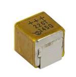
T25
www.vishay.com
Vishay
Solid Tantalum SMD Capacitors TANTAMOUNT™,
Hi-Rel COTS, Low ESR, Metal Case
FEATURES
• High reliability; burn-in at a minimum of rated
DC voltage for a minimum of 40 h
Available
• Surge current testing per MIL-PRF-55365
option available
Available
• Low ESR
• Lead (Pb)-free terminations available (tin / lead
terminations are under development)
Available
• Mounting: surface-mount
PERFORMANCE CHARACTERISTICS
• Material categorization: for definitions of compliance
please see www.vishay.com/doc?99912
Operating Temperature: -55 °C to +125 °C
(above 85 °C, voltage derating is required)
Capacitance Range: 22 μF to 330 μF
Capacitance Tolerance: ± 10 %, ± 20 %
Voltage Rating: 16 VDC to 50 VDC
Note
* This datasheet provides information about parts that are
RoHS-compliant and / or parts that are non RoHS-compliant. For
example, parts with lead (Pb) terminations are not RoHS-compliant.
Please see the information / tables in this datasheet for details
ORDERING INFORMATION
T25
D
226
K
050
E
S
A
TYPE
CASE
CODE
CAPACITANCE
CAPACITANCE
TOLERANCE
DC VOLTAGE
RATING AT +85 °C
TERMINATION /
PACKAGING
(available options are
series dependent)
RELIABILITY
GRADE
SURGE
CURRENT
OPTION
See
Ratings
and
Case
Codes
table
This is expressed
in pF. The first two
digits are the
significant figures.
The third is the
number of zeros
to follow.
K = ± 10 %
M = ± 20 %
This is expressed
in volts. To complete
the three-digit block,
zeros precede the
voltage rating.
A decimal point is
indicated by an “R”
(6R3 = 6.3 V).
C = 100 % tin /
7" (178 mm), reel
H = 100 % tin /
7" (178 mm), 1/2 reel
E = Sn / Pb solder /
7" (178 mm) reel
L = Sn / Pb solder /
7" (178 mm), 1/2 reel
S = 40 h
burn-in
Z = non ER
A = 10 cycles
at +25 °C
B = 10 cycles
at -55 °C /
+85 °C
C = 10 cycles
at -55 °C /
+85 °C
(before burn-in)
S = 3 cycles
at 25 °C
Z = no surge
current
DIMENSIONS in inches [millimeters]
H
L1
TW
TW
P
W
P
L
CASE CODE
L (MAX.)
L1
W
H
P
TW
WEIGHT
g
(AVERAGE)
D
0.326
[8.5]
0.283 ± 0.008
[7.2 ± 0.2]
0.275 ± 0.008
[7.0 ± 0.2]
0.291 ± 0.008
[7.4 ± 0.2]
0.098 ± 0.008
[2.5 ± 0.2]
0.197 ± 0.008
[5.0 ± 0.2]
1.80
Revision: 16-Aug-2021
Document Number: 40171
1
For technical questions, contact: tantalum@vishay.com
THIS DOCUMENT IS SUBJECT TO CHANGE WITHOUT NOTICE. THE PRODUCTS DESCRIBED HEREIN AND THIS DOCUMENT
ARE SUBJECT TO SPECIFIC DISCLAIMERS, SET FORTH AT www.vishay.com/doc?91000
�T25
www.vishay.com
Vishay
RATINGS AND CASE CODES
μF
16 V
20 V
25 V
35 V
50 V
22
D
33
47
D (1)
68
D (1)
100
150
D (1)
220
330
D
Note
(1) Preliminary values, contact factory for availability
MARKING
VOLTAGE CODE
V
CODE
16
C
20
D
Voltage code
25
E
Week
35
V
50
T
+++
Capacitance
Year
2
337C
YYXX
Vishay marking
STANDARD RATINGS
CAPACITANCE
(μF)
CASE CODE
PART NUMBER
330
D
T25D337(1)016(2)(3)(4)
MAX. DCL
AT +25 °C
(μA)
MAX. DF
AT +25 °C
(%)
MAX. ESR
AT +25 °C
100 kHz
(mΩ)
MAX.
RIPPLE
100 kHz
IRMS (A)
14
180
1.5
500
0.9
16 VDC AT +85 °C; 10 VDC AT +125 °C
52.8
20 VDC AT +85 °C; 13 VDC AT +125 °C
220
D (1)
T25D227(1)020(2)(3)(4)
In development
25 VDC AT +85 °C; 17 VDC AT +125 °C
100
D (1)
T25D107(1)025(2)(3)(4)
68
D (1)
T25D686(1)035(2)(3)(4)
22
D
T25D226(1)050(2)(3)(4)
In development
35 VDC AT +85 °C; 23 VDC AT +125 °C
In development
50 VDC AT +85 °C; 33 VDC AT +125 °C
11
6
Notes
• Part number definitions:
(1) Capacitance tolerance: K, M
(2) Termination and packaging: C, H, E, L
(3) Reliability level: S, Z
(4) Surge current: A, B, S, C, Z
(1) Rating in development, contact factory for availability
Revision: 16-Aug-2021
Document Number: 40171
2
For technical questions, contact: tantalum@vishay.com
THIS DOCUMENT IS SUBJECT TO CHANGE WITHOUT NOTICE. THE PRODUCTS DESCRIBED HEREIN AND THIS DOCUMENT
ARE SUBJECT TO SPECIFIC DISCLAIMERS, SET FORTH AT www.vishay.com/doc?91000
�T25
www.vishay.com
Vishay
VOLTAGE DERATING GUIDELINES (below +85 °C)
VOLTAGE RAIL (V)
CAPACITOR RATED VOLTAGE (V)
3.3
6.3
5
10
10
20
12
25
15
35
≥ 24
50 or series configuration
Note
• For more information about recommended voltage derating see technical note www.vishay.com/doc?40246
CARRIER TAPE DIMENSIONS in inches [millimeters]
TYPE
CASE CODE
TAPE WIDTH W
(mm)
P1
K0 MAX.
B1 MAX.
T25
D
16
0.476 ± 0.004
[12.0 ± 0.1]
0.3
[7.86]
0.45
[11.3]
POWER DISSIPATION
CASE CODE
MAXIMUM PERMISSIBLE POWER DISSIPATION AT +25 °C (W) IN FREE AIR
D
0.408
STANDARD PACKAGING QUANTITY
UNITS PER REEL
CASE CODE
D
7" FULL REEL
7" HALF REEL
100
50
CAPACITOR ELECTRICAL PERFORMANCE CHARACTERISTICS
ITEM
PERFORMANCE CHARACTERISTICS
Category temperature range
-55 °C to +85 °C (to +125 °C with voltage derating)
Capacitance tolerance
± 20 %, ± 10 %, tested via bridge method, at +25 °C, 120 Hz
Dissipation factor
Limit per Standard Ratings table. Tested via bridge method, at 25 °C, 120 Hz.
ESR
Limit per Standard Ratings table. Tested via bridge method, at 25 °C, 100 kHz.
Leakage current
After application of rated voltage applied to capacitors for 5 min using a steady source of power with
1 kΩ resistor in series with the capacitor under test, leakage current at 25 °C is not more than described
in Standard Ratings table. Note that the leakage current varies with temperature and applied voltage. See
graph below for the appropriate adjustment factor.
Capacitance change by
temperature
+12 % max. (at +125 °C)
+10 % max. (at +85 °C)
-10 % max. (at -55 °C)
For capacitance value > 300 μF
+20 % max. (at +125 °C)
+15 % max. (at +85 °C)
-15 % max. (at -55 °C)
Reverse voltage
Capacitors are capable of withstanding peak voltages in the reverse direction equal to:
10 % of the DC rating at +25 °C
5 % of the DC rating at +85 °C
Vishay does not recommend intentional or repetitive application of reverse voltage.
Ripple current and
temperature derating
For maximum permissible ripple current (IRMS) or / and voltage (VRMS) please refer to product datasheet
and Guide to Application. If capacitors are to be used at temperatures above +25 °C, the permissible
RMS ripple current or voltage shall be calculated using the derating factors:
1.0 at +25 °C
0.9 at +85 °C
0.4 at +125 °C
Revision: 16-Aug-2021
Document Number: 40171
3
For technical questions, contact: tantalum@vishay.com
THIS DOCUMENT IS SUBJECT TO CHANGE WITHOUT NOTICE. THE PRODUCTS DESCRIBED HEREIN AND THIS DOCUMENT
ARE SUBJECT TO SPECIFIC DISCLAIMERS, SET FORTH AT www.vishay.com/doc?91000
�T25
www.vishay.com
Vishay
CAPACITOR ELECTRICAL PERFORMANCE CHARACTERISTICS
ITEM
PERFORMANCE CHARACTERISTICS
Maximum operating voltage
OPERATING TEMPERATURE
+85 °C
+125 °C
RATED VOLTAGE
(V)
SURGE VOLTAGE
(V)
RATED VOLTAGE
(V)
SURGE VOLTAGE
(V)
16
20
10
12
20
26
13
16
25
32
17
20
35
46
23
28
50
65
33
40
Note
• All information presented in this document reflects typical performance characteristics
TYPICAL LEAKAGE CURRENT FACTOR RANGE
100
Leakage Current Factor
+125 °C
10
+85 °C
+55 °C
+25 °C
1.0
0 °C
0.1
-55 °C
0.01
0.001
0
10
20
30
40
50
60
70
80
90
100
Percent of Rated Voltage
Notes
• At +25 °C, the leakage current shall not exceed the value listed in the Standard Ratings table
• At +85 °C, the leakage current shall not exceed 10 times the value listed in the Standard Ratings table
• At +125 °C, the leakage current shall not exceed 12 times the value listed in the Standard Ratings table
CAPACITOR PERFORMANCE CHARACTERISTICS
ITEM
CONDITION
POST TEST PERFORMANCE
Surge voltage
85 °C, 1000 successive test cycles at 1.3 of rated
voltage in series with a 1 kΩ resistor at the rate of 30 s
ON, 30 s OFF, MIL-PRF-55365
Capacitance change
Dissipation factor
Leakage current
Within ± 10 % of initial
Not to exceed initial
Not to exceed initial
Life test at +85 °C
2000 h application of rated voltage at 85 °C,
MIL-STD-202 method 108
Capacitance change
Leakage current
Within ± 10 % of initial
Not to exceed 125 % of initial
Life test at +125 °C
1000 h application of 2/3 rated voltage at 125 °C,
MIL-STD-202 method 108
Capacitance change
Leakage current
Within ± 20 % of initial
Not to exceed 125 % of initial
Revision: 16-Aug-2021
Document Number: 40171
4
For technical questions, contact: tantalum@vishay.com
THIS DOCUMENT IS SUBJECT TO CHANGE WITHOUT NOTICE. THE PRODUCTS DESCRIBED HEREIN AND THIS DOCUMENT
ARE SUBJECT TO SPECIFIC DISCLAIMERS, SET FORTH AT www.vishay.com/doc?91000
�T25
www.vishay.com
Vishay
CAPACITOR ENVIRONMENTAL CHARACTERISTICS
ITEM
CONDITION
POST TEST PERFORMANCE
Moisture resistance
MIL-STD-202, method 106, at rated voltage.
Capacitance change
Cap. ≤ 600 μF
Cap. > 600 μF
Dissipation factor
Leakage current
Thermal shock
Salt atmosphere
(corrosion)
Within ± 10 % of initial value
Within ± 20 % of initial value
Initial specified value or less
Initial specified value or less
Capacitors are subjected to 6 cycles per MIL-STD-202
method 107 of the following:
-55 °C (+0 °C, -6 °C) for 30 min, then
+25 °C (+3 °C, -3 °C) for 5 min, then
+85 °C (+4 °C, -5 °C) for 40 min, then
+125 °C (+4 °C, -0 °C) for 30 min, then
+25 °C (+3 °C, -3 °C) for 5 min
Capacitance change
Cap.
Dissipation factor
Leakage current
Test per MIL-202, method 101, condition B (48 h).
5 % salt solution applying.
No harmful or extensive corrosion, = 90 % protection of
exposed metallic surfaces by finish, markings legible,
= 10 % corrosion of the terminal hardware or mounting.
Within ± 15 % of initial
Initial specified value or less
Initial specified value multiplied
by 12 or less
MECHANICAL PERFORMANCE CHARACTERISTICS
TEST CONDITION
CONDITION
POST TEST PERFORMANCE
Shear test
Apply a pressure load of 5 N for 10 s ± 1 s horizontally
to the center of capacitor side body.
AEC-Q200-006
There shall be no visual damage when viewed at 20 x
magnification and the component shall meet the original
electrical requirements.
Vibration
MIL-STD-202, method 204, condition D,
10 Hz to 2000 Hz, 20 g peak
There shall be no mechanical or visual damage to
capacitors post-conditioning.
Shock
(specified pulse)
MIL-STD-202, method 213, condition I,
100 g peak
Capacitance change
Dissipation factor
Leakage current
Within ± 10 % of initial
Initial specified value or less
Initial specified value or less
There shall be no mechanical or visual damage to
capacitors post-conditioning.
Resistance to
soldering heat
MIL-STD-202, method 210, condition J,
except with only one heat cycle.
Capacitance change
Dissipation factor
Leakage current
Within ± 10 % of initial
Initial specified value or less
Initial specified value or less
There shall be no mechanical or visual damage to
capacitors post-conditioning.
Solderability
MIL-STD-202, method 208, ANSI/J-STD-002, test B.
Applies only to solder and tin plated terminations.
Does not apply to gold terminations.
All terminations shall exhibit a continuous solder coating
free from defects for a minimum of 95 % of the critical area
of any individual lead.
Resistance to solvent
MIL-STD-202, method 215
Marking has to remain legible, no degradation of the can
material.
Sleeving
MIL-PRF-39003, paragraph 3.22:
apply a DC potential of 2000 V.
Maximum leakage of 20 μA is allowed between the
capacitor case and the fixture.
Seal
MIL-STD-202, method 112, condition A or D
There shall be no visual leakage.
Revision: 16-Aug-2021
Document Number: 40171
5
For technical questions, contact: tantalum@vishay.com
THIS DOCUMENT IS SUBJECT TO CHANGE WITHOUT NOTICE. THE PRODUCTS DESCRIBED HEREIN AND THIS DOCUMENT
ARE SUBJECT TO SPECIFIC DISCLAIMERS, SET FORTH AT www.vishay.com/doc?91000
�T25
www.vishay.com
Vishay
RECOMMENDED REFLOW PROFILES
Capacitors should withstand reflow profile as per J-STD-020 standard
TEMPERATURE (°C)
TP
TL
Ts max.
TC = 5 °C
tp
Max. ramp-up rate = 3 °C/s
Max. ramp-down rate = 6 °C/s
tL
Preheat area
Ts min.
ts
25
Time 25 °C to peak
TIME (s)
PROFILE FEATURE
SnPb EUTECTIC ASSEMBLY
LEAD (Pb)-FREE ASSEMBLY
Temperature min. (Ts min.)
100 °C
150 °C
Temperature max. (Ts max.)
150 °C
200 °C
60 s to 120 s
60 s to 120 s
3 °C/s max.
3 °C/s max.
Preheat / soak
Time (ts) from (Ts min. to Ts max.)
Ramp-up
Ramp-up rate (TL to TP)
Liquidus temperature (TL)
183 °C
217 °C
60 s to 150 s
60 s to 150 s
Peak package body temperature (Tp)
220
250
Time (tp) within 5 °C of the specified
classification temperature (TC)
20 s
30 s
6 min max.
8 min max.
Ramp-down rate (TP to TL)
6 °C/s max.
6 °C/s max.
Time 25 °C to peak temperature
6 min max.
8 min max.
Time (tL) maintained above TL
Time 25 °C to peak temperature
Ramp-down
PAD DIMENSIONS in inches [millimeters]
D
B
C
A
CASE CODE
A
(MIN.)
B
(NOM.)
C
(NOM.)
D
(NOM.)
D
0.276 [7]
0.178 [4.5]
0.079 [2]
0.433 [11]
Revision: 16-Aug-2021
Document Number: 40171
6
For technical questions, contact: tantalum@vishay.com
THIS DOCUMENT IS SUBJECT TO CHANGE WITHOUT NOTICE. THE PRODUCTS DESCRIBED HEREIN AND THIS DOCUMENT
ARE SUBJECT TO SPECIFIC DISCLAIMERS, SET FORTH AT www.vishay.com/doc?91000
�Legal Disclaimer Notice
www.vishay.com
Vishay
Disclaimer
ALL PRODUCT, PRODUCT SPECIFICATIONS AND DATA ARE SUBJECT TO CHANGE WITHOUT NOTICE TO IMPROVE
RELIABILITY, FUNCTION OR DESIGN OR OTHERWISE.
Vishay Intertechnology, Inc., its affiliates, agents, and employees, and all persons acting on its or their behalf (collectively,
“Vishay”), disclaim any and all liability for any errors, inaccuracies or incompleteness contained in any datasheet or in any other
disclosure relating to any product.
Vishay makes no warranty, representation or guarantee regarding the suitability of the products for any particular purpose or
the continuing production of any product. To the maximum extent permitted by applicable law, Vishay disclaims (i) any and all
liability arising out of the application or use of any product, (ii) any and all liability, including without limitation special,
consequential or incidental damages, and (iii) any and all implied warranties, including warranties of fitness for particular
purpose, non-infringement and merchantability.
Statements regarding the suitability of products for certain types of applications are based on Vishay's knowledge of typical
requirements that are often placed on Vishay products in generic applications. Such statements are not binding statements
about the suitability of products for a particular application. It is the customer's responsibility to validate that a particular product
with the properties described in the product specification is suitable for use in a particular application. Parameters provided in
datasheets and / or specifications may vary in different applications and performance may vary over time. All operating
parameters, including typical parameters, must be validated for each customer application by the customer's technical experts.
Product specifications do not expand or otherwise modify Vishay's terms and conditions of purchase, including but not limited
to the warranty expressed therein.
Hyperlinks included in this datasheet may direct users to third-party websites. These links are provided as a convenience and
for informational purposes only. Inclusion of these hyperlinks does not constitute an endorsement or an approval by Vishay of
any of the products, services or opinions of the corporation, organization or individual associated with the third-party website.
Vishay disclaims any and all liability and bears no responsibility for the accuracy, legality or content of the third-party website
or for that of subsequent links.
Except as expressly indicated in writing, Vishay products are not designed for use in medical, life-saving, or life-sustaining
applications or for any other application in which the failure of the Vishay product could result in personal injury or death.
Customers using or selling Vishay products not expressly indicated for use in such applications do so at their own risk. Please
contact authorized Vishay personnel to obtain written terms and conditions regarding products designed for such applications.
No license, express or implied, by estoppel or otherwise, to any intellectual property rights is granted by this document or by
any conduct of Vishay. Product names and markings noted herein may be trademarks of their respective owners.
© 2022 VISHAY INTERTECHNOLOGY, INC. ALL RIGHTS RESERVED
Revision: 01-Jan-2022
1
Document Number: 91000
�