T93
www.vishay.com
Vishay Sfernice
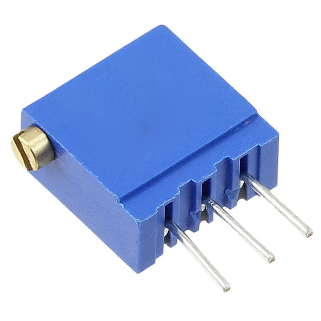
3/8" Square Multi-Turn Cermet Trimmer
FEATURES
• Industrial grade
• 0.5 W at 70 °C
• Tests according to CECC 41000 or IEC 60393-1
DESIGN SUPPORT TOOLS
• Contact resistance variation < 2 %
click logo to get started
• Material categorization: for definitions of compliance
please see www.vishay.com/doc?99912
Models
Available
The T93 is a small size trimmer - 3/8" x 3/8" x 3/16" - answering PC board mounting requirements. Five versions are available
which differ by the position of the control screw in relation to the PC board plane and by the spacing of the terminals. Excellent
operational stability is provided by the use of a cermet element.
DIMENSIONS in millimeters (± 0.5 mm)
T93XA
9.8 max. 5 ± 1
5 max
2.3 ± 0.2 (1)
a
b
c
2.54
2.54
Terminal Spacing on
a 2.54 PCB
a
b
c
9.7 max
ø 0.5
1.3
0.5
ø 2.2
Slot 0.6 x 0.6
1.2 ± 0.2
7.9 ± 0.2
T93XB
9.8 max
0.6 ± 0.2 (1)
5±1
5 max
a
b
c
2.54
2.54 (1)
2.54 (1)
a
b
c
9.7 max
ø 0.5
1.3
0.5
ø 2.2
1.2 ± 0.2
Slot 0.6 x 0.6
7.9 ± 0.2
T93YA
1.3
2.3 ± 0.2 (1)
9.8 max
1.2 ± 0.1
5±1
1.6 ± 0.1
ø 2.2
a
b
c
2.54 (1)
2.54 (1)
9.7 max
ø 0.5
a
b
c
slot 0.6 x 0.6
0.5
T93YB
0.6 ± 0.2 (1)
1.3
9.8 max
5 max
1.2 ± 0.1
5±1
2.54
ø 2.2
a
b
c
(1)
2.54
2.54 (1)
1.6 ± 0.1
9.7 max
ø 0.5
slot 0.6 x 0.6
5 max
0.5
T93Z
5.2 max
4.8 ± 0.2 (1)
5±1
2.54 (1)
Slot 0.6 x 0.6
a
b
c
c
b
a
9.7 max
2.54 (1)
2.54 (1)
ø 2.2
ø 0.5
c
b
a
Base level
1.3
0.5
1.3 ± 0.1
9.7 max.
1.2 ± 0.1
Note
(1) To be measured at base level
Revision: 26-Jan-18
Document Number: 51026
1
For technical questions, contact: sferpottrimmers@vishay.com
THIS DOCUMENT IS SUBJECT TO CHANGE WITHOUT NOTICE. THE PRODUCTS DESCRIBED HEREIN AND THIS DOCUMENT
ARE SUBJECT TO SPECIFIC DISCLAIMERS, SET FORTH AT www.vishay.com/doc?91000
�T93
www.vishay.com
Vishay Sfernice
ELECTRICAL SPECIFICATIONS
Resistive element
Cermet
Electrical travel
21 turns ± 2
10 to 2.2 M
Resistance range
Standard series E3
Tolerance
1 - 2.2 - 4.7 and on request 1 - 2 - 5
Standard
10 %
On request
5%
linear
0.5 W at +70 °C
Power rating
POWER IN W
0.5
0
0
25
50
70
125
100
155
AMBIENT TEMPERATURE IN °C
c
a
Circuit diagram
(3)
(1)
cw
b
(2)
Temperature coefficient
Limiting element voltage (linear law)
Contact resistance variation
End resistance (typical)
See Standard Resistance Element table
250 V
2 % Rn or 2
1
Dielectric strength (RMS)
1000 V
Insulation resistance (500 VDC)
106 M
MECHANICAL SPECIFICATIONS
Mechanical travel
Operating torque (max. Ncm)
End stop torque
Net weight
Wiper (actual travel)
Terminals
23 turns ± 5
1.5
Clutch action
Approx. 0.82 g
Positioned at approx. 50 %
Pure Sn (code e3)
ENVIRONMENTAL SPECIFICATIONS
Temperature range
Climatic category
Sealing
Revision: 26-Jan-18
-55 °C to +125 °C
55/125/56
Fully sealed - IP67
Document Number: 51026
2
For technical questions, contact: sferpottrimmers@vishay.com
THIS DOCUMENT IS SUBJECT TO CHANGE WITHOUT NOTICE. THE PRODUCTS DESCRIBED HEREIN AND THIS DOCUMENT
ARE SUBJECT TO SPECIFIC DISCLAIMERS, SET FORTH AT www.vishay.com/doc?91000
�T93
www.vishay.com
Vishay Sfernice
STANDARD RESISTANCE ELEMENT DATA
STANDARD
RESISTANCE
VALUES
LINEAR LAW
MAX. POWER
AT 70 °C
MAX. WORKING
VOLTAGE
MAX. CURRENT
THROUGH WIPER
TYPICAL
TCR
-55 °C
+125 °C
W
V
mA
ppm/°C
10
22
47
100
220
470
1K
2.2K
4.7K
10K
22K
47K
100K
220K
470K
1M
2.2M
0.5
0.5
0.5
0.5
0.5
0.5
0.5
0.5
0.5
0.5
0.5
0.5
0.5
0.28
0.13
0.06
0.028
2.2
3.3
4.8
7
10.5
15.3
22.4
33.2
48.5
70.7
105
153
224
250
250
250
250
224
150
103
70
47
32
22
15
10
7
4.8
3.2
2.2
1.1
0.53
0.25
0.11
± 100
PERFORMANCES
TESTS
Load life
Climatic sequence
Long term damp heat
Rapid temperature change
Shock
Vibration
Rotational life
TYPICAL VALUES AND DRIFTS
CONDITIONS
RT/RT (%)
R1-2/R1-2 (%)
1000 h at rated power
90'/30' - ambient temp. 70 °C
±1%
Contact res. variation: < 1 % Rn
±2%
Phase A dry heat 125 °C - 30 % Pr
Phase B damp heat
Phase C cold -55 °C
Phase D damp heat 5 cycles
± 0.5 %
±1%
56 days
40 °C, 93 % RH
± 0.5 %
Dielectric strength: 1000 VRMS
Insulation resistance: > 104 M
±1%
5 cycles
-55 °C to +125 °C
± 0.5 %
V1-2/V1-3 ± 1 %
50 g at 11 ms
3 successive shocks
in 3 directions
± 0.1 %
± 0.2 %
10 Hz to 55 Hz
0.75 mm or 10 g
during 6 h
± 0.1 %
V1-2/V1-3 ± 0.2 %
200 cycles
±4%
Contact res. variation: < 1 % Rn
-
Note
• Nothing stated herein shall be construed as a guarantee of quality or durability
MARKING
•
•
•
•
•
•
•
Vishay trademark
Model
Style
Ohmic value (in , k, M)
Tolerance (in %)
Manufacturing date
Marking of terminal 3
Revision: 26-Jan-18
Document Number: 51026
3
For technical questions, contact: sferpottrimmers@vishay.com
THIS DOCUMENT IS SUBJECT TO CHANGE WITHOUT NOTICE. THE PRODUCTS DESCRIBED HEREIN AND THIS DOCUMENT
ARE SUBJECT TO SPECIFIC DISCLAIMERS, SET FORTH AT www.vishay.com/doc?91000
�T93
www.vishay.com
Vishay Sfernice
PACKAGING
• In tube of 50 pieces code T20 (TU50)
ORDERING INFORMATION (part number)
T
9
3
X
A
2
2
4
K
T
2
0
Model
STYLE
OHMIC VALUE
TOLERANCE
PACKAGING
T93
XA
XB
YA
YB
Z
From
10 to 2.2 M
224 = 220 k
K = 10 %
on request J = 5 %
T20 = tube
50 pieces
SPECIAL
NUMBER
(If applicable)
Given by
Vishay
for custom
design
DESCRIPTION (for information only)
T93
XA
220K
10 %
MODEL
STYLE
VALUE
TOLERANCE
SPECIAL
TU50
e3
PACKAGING
LEAD FINISH
RELATED DOCUMENTS
APPLICATION NOTES
Potentiometers and Trimmers
www.vishay.com/doc?51001
Guidelines for Vishay Sfernice Resistive and Inductive Components
www.vishay.com/doc?52029
Revision: 26-Jan-18
Document Number: 51026
4
For technical questions, contact: sferpottrimmers@vishay.com
THIS DOCUMENT IS SUBJECT TO CHANGE WITHOUT NOTICE. THE PRODUCTS DESCRIBED HEREIN AND THIS DOCUMENT
ARE SUBJECT TO SPECIFIC DISCLAIMERS, SET FORTH AT www.vishay.com/doc?91000
�Legal Disclaimer Notice
www.vishay.com
Vishay
Disclaimer
ALL PRODUCT, PRODUCT SPECIFICATIONS AND DATA ARE SUBJECT TO CHANGE WITHOUT NOTICE TO IMPROVE
RELIABILITY, FUNCTION OR DESIGN OR OTHERWISE.
Vishay Intertechnology, Inc., its affiliates, agents, and employees, and all persons acting on its or their behalf (collectively,
“Vishay”), disclaim any and all liability for any errors, inaccuracies or incompleteness contained in any datasheet or in any other
disclosure relating to any product.
Vishay makes no warranty, representation or guarantee regarding the suitability of the products for any particular purpose or
the continuing production of any product. To the maximum extent permitted by applicable law, Vishay disclaims (i) any and all
liability arising out of the application or use of any product, (ii) any and all liability, including without limitation special,
consequential or incidental damages, and (iii) any and all implied warranties, including warranties of fitness for particular
purpose, non-infringement and merchantability.
Statements regarding the suitability of products for certain types of applications are based on Vishay's knowledge of typical
requirements that are often placed on Vishay products in generic applications. Such statements are not binding statements
about the suitability of products for a particular application. It is the customer's responsibility to validate that a particular product
with the properties described in the product specification is suitable for use in a particular application. Parameters provided in
datasheets and / or specifications may vary in different applications and performance may vary over time. All operating
parameters, including typical parameters, must be validated for each customer application by the customer's technical experts.
Product specifications do not expand or otherwise modify Vishay's terms and conditions of purchase, including but not limited
to the warranty expressed therein.
Hyperlinks included in this datasheet may direct users to third-party websites. These links are provided as a convenience and
for informational purposes only. Inclusion of these hyperlinks does not constitute an endorsement or an approval by Vishay of
any of the products, services or opinions of the corporation, organization or individual associated with the third-party website.
Vishay disclaims any and all liability and bears no responsibility for the accuracy, legality or content of the third-party website
or for that of subsequent links.
Except as expressly indicated in writing, Vishay products are not designed for use in medical, life-saving, or life-sustaining
applications or for any other application in which the failure of the Vishay product could result in personal injury or death.
Customers using or selling Vishay products not expressly indicated for use in such applications do so at their own risk. Please
contact authorized Vishay personnel to obtain written terms and conditions regarding products designed for such applications.
No license, express or implied, by estoppel or otherwise, to any intellectual property rights is granted by this document or by
any conduct of Vishay. Product names and markings noted herein may be trademarks of their respective owners.
© 2022 VISHAY INTERTECHNOLOGY, INC. ALL RIGHTS RESERVED
Revision: 01-Jan-2022
1
Document Number: 91000
�
很抱歉,暂时无法提供与“T93XB202KT20”相匹配的价格&库存,您可以联系我们找货
免费人工找货- 国内价格
- 1+13.48816
- 10+12.02559
- 16+7.39411
- 42+6.98784
- 国内价格
- 5+12.48411
- 15+12.20919
- 25+11.94676
- 国内价格
- 15+12.20919
- 25+11.94676
- 国内价格
- 50+9.32560
- 100+9.09233
- 200+8.95278