TDSG3150, TDSG3160, TDSO3150, TDSO3155, TDSO3160, TDSY3150
www.vishay.com
Vishay Semiconductors
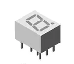
Standard 7-Segment Display 10 mm
FEATURES
• Evenly lighted segments
• Grey package surface
• Untinted segments
• Luminous intensity categorized
• Yellow and green categorized for color
• Wide viewing angle
19236
• Suitable for DC and high peak current
DESCRIPTION
• Material categorization: for definitions of compliance
please see www.vishay.com/doc?99912
The TDS.31.. series are 10 mm character seven segment
LED displays in a very compact package.
APPLICATIONS
The displays are designed for a viewing distance up to
6 m and available in four bright colors. The grey package
surface and the evenly lighted untinted segments provide an
optimum on-off contrast.
• Panel meters
• Test- and measure-equipment
• Point-of-sale terminals
All displays are categorized in luminous intensity groups.
That allows users to assemble displays with uniform
appearance. Typical applications include instruments, panel
meters, point-of-sale terminals and household equipment.
• Control units
Due to the design of 10 mm displays, a certain amount of
cross-talk between segments is unavoidable. This light
leakage becomes more noticeable as the brightness of the
operated
segments
increases.
However,
higher
environmental illumination, or a partially transparent cover,
may reduce this effect. Therefore, it's important to consider
this phenomenon during design-in and to validate suitability
• Package: 10 mm
PRODUCT GROUP AND PACKAGE DATA
• Product group: display
• Product series: standard
• Angle of half intensity: ± 50°
for the particular application and all its operation modes.
PARTS TABLE
PART
LUMINOUS
INTENSITY
(μcd)
COLOR
MIN.
TYP.
MAX.
450
4500
-
at
IF
(mA)
10
WAVELENGTH
(nm)
at FORWARD VOLTAGE at
(V)
IF
IF
(mA)
(mA)
MIN. TYP. MAX.
MIN. TYP. MAX.
612
-
625
10
-
2
3
20
CIRCUITRY
TDSO3150
Orange red
Common anode
TDSO3150-KL
Orange red
1800
-
5600
10
612
-
625
10
-
2
3
20
Common anode
TDSO3150-L
Orange red
2800
-
5600
10
612
-
625
10
-
2
3
20
Common anode
TDSO3155
Orange red
1100
-
9000
10
612
-
625
10
-
2
3
20
Common anode
TDSO3160
Orange red
450
4500
-
10
612
-
625
10
-
2
3
20
Common cathode
TDSO3160-KL
Orange red
1800
-
5600
10
612
-
625
10
-
2
3
20
Common cathode
TDSO3160-L
Orange red
2800
-
5600
10
612
-
625
10
-
2
3
20
Common cathode
TDSY3150 (1)
Yellow
450
3000
-
10
581
-
594
10
-
2.4
3
20
Common anode
TDSY3150-K (1)
Yellow
1800
-
3600
10
581
-
594
10
-
2.4
3
20
Common anode
TDSG3150
Green
450
6800
-
10
562
-
575
10
-
2.4
3
20
Common anode
TDSG3150-M
Green
4500
-
9000
10
562
-
575
10
-
2.4
3
20
Common anode
TDSG3150-MN
Green
4500
-
14 000
10
562
-
575
10
-
2.4
3
20
Common anode
TDSG3160
Green
450
6800
-
10
562
-
575
10
-
2.4
3
20
Common cathode
TDSG3160-M
Green
4500
-
9000
10
562
-
575
10
-
2.4
3
20
Common cathode
Note
(1) Not for new designs
Rev. 2.5, 06-Dec-2021
Document Number: 83125
1
For technical questions, contact: LED@Vishay.com
THIS DOCUMENT IS SUBJECT TO CHANGE WITHOUT NOTICE. THE PRODUCTS DESCRIBED HEREIN AND THIS DOCUMENT
ARE SUBJECT TO SPECIFIC DISCLAIMERS, SET FORTH AT www.vishay.com/doc?91000
�TDSG3150, TDSG3160, TDSO3150, TDSO3155, TDSO3160, TDSY3150
www.vishay.com
Vishay Semiconductors
ABSOLUTE MAXIMUM RATINGS (Tamb = 25 °C, unless otherwise specified)
TDSO315., TDSO316., TDSY315., TDSG315., TDSG316.
PARAMETER
SYMBOL
VALUE
Reverse voltage per segment or DP
VR
6
V
DC forward current per segment or DP
IF
20
mA
tp ≤ 10 μs (non repetitive)
IFSM
0.15
A
Tamb ≤ 45 °C
PV
480
mW
DC forward current per segment or DP
Power dissipation
TEST CONDITION
Junction temperature
UNIT
Tj
100
°C
Operating temperature range
Tamb
-40 to +85
°C
Storage temperature range
Tstg
-40 to +85
°C
Tsd
260
°C
RthJA
120
K/W
Soldering temperature
t ≤ 3 s, 2 mm below seating plane
Thermal resistance LED junction to ambient
OPTICAL AND ELECTRICAL CHARACTERISTICS (Tamb = 25 °C, unless otherwise specified)
TDSO3150, TDSO3150-KL, TDSO3150-L, TDSO3155, TDSO3160, TDSO3160-KL, TDSO3160-L, ORANGE RED
PARAMETER
Luminous intensity per segment
(digit average) (1)
TEST CONDITION
IF = 10 mA
Dominant wavelength
IF = 10 mA
Peak wavelength
IF = 10 mA
Angle of half intensity
IF = 10 mA
Forward voltage per segment or DP
IF = 20 mA
Reverse voltage per segment or DP
IR = 10 μA
MIN.
TYP.
MAX.
TDSO3150
PART
450
4500
-
TDSO3150-KL
1800
-
5600
TDSO3150-L
2800
-
5600
1100
-
9000
TDSO3155
SYMBOL
IV
TDSO3160
450
4500
-
TDSO3160-KL
1800
-
5600
TDSO3160-L
2800
-
5600
TDSO3150,
TDSO3150-KL,
TDSO3150-L,
TDSO3155,
TDSO3160,
TDSO3160-KL,
TDSO3160-L
UNIT
μcd
λd
612
-
625
nm
λp
-
630
-
nm
j
-
± 50
-
°
VF
-
2
3
V
VR
6
15
-
V
Note
(1) I
Vmin. and IV groups are mean values of all segments (a to g, D1 to D4), matching factor within segments is ≥ 0.5, excluding decimal points
and colon
OPTICAL AND ELECTRICAL CHARACTERISTICS (Tamb = 25 °C, unless otherwise specified)
TDSY3150, TDSY3150-K, YELLOW
PARAMETER
TEST CONDITION
Luminous intensity per segment
(digit average) (1)
IF = 10 mA
Dominant wavelength
IF = 10 mA
PART
TDSY3150
TDSY3150-K
SYMBOL
IV
λd
MIN.
TYP.
MAX.
450
3000
-
UNIT
1800
-
3600
581
-
594
nm
nm
μcd
λp
-
585
-
j
-
± 50
-
°
IF = 20 mA
VF
-
2.4
3
V
IR = 10 μA
VR
6
15
-
V
Peak wavelength
IF = 10 mA
Angle of half intensity
IF = 10 mA
Forward voltage per segment or DP
Reverse voltage per segment or DP
TDSY3150,
TDSY3150-K
Note
(1) I
Vmin. and IV groups are mean values of all segments (a to g, D1 to D4), matching factor within segments is ≥ 0.5, excluding decimal points
and colon
Rev. 2.5, 06-Dec-2021
Document Number: 83125
2
For technical questions, contact: LED@Vishay.com
THIS DOCUMENT IS SUBJECT TO CHANGE WITHOUT NOTICE. THE PRODUCTS DESCRIBED HEREIN AND THIS DOCUMENT
ARE SUBJECT TO SPECIFIC DISCLAIMERS, SET FORTH AT www.vishay.com/doc?91000
�TDSG3150, TDSG3160, TDSO3150, TDSO3155, TDSO3160, TDSY3150
www.vishay.com
Vishay Semiconductors
OPTICAL AND ELECTRICAL CHARACTERISTICS (Tamb = 25 °C, unless otherwise specified)
TDSG315., TDSG316., GREEN
PARAMETER
TEST CONDITION
PART
SYMBOL
TDSG3150
TDSG3150-M
Luminous intensity per segment
(digit average) (1)
IF = 10 mA
TDSG3150-MN
IV
TDSG3160
TDSG3160-M
Dominant wavelength
IF = 10 mA
Peak wavelength
IF = 10 mA
Angle of half intensity
IF = 10 mA
Forward voltage per segment or DP
IF = 20 mA
Reverse voltage per segment or DP
IR = 10 μA
TDSG3150,
TDSG3150-M,
TDSG3150-MN,
TDSG3160,
TDSG3160-M
MIN.
TYP.
MAX.
450
6800
-
4500
-
9000
4500
-
14 000
450
6800
-
UNIT
μcd
4500
-
9000
λd
562
-
575
nm
λp
-
565
-
nm
j
-
± 50
-
°
VF
-
2.4
3
V
VR
6
15
-
V
Note
(1) I
Vmin. and IV groups are mean values of all segments (a to g, D1 to D4), matching factor within segments is ≥ 0.5, excluding decimal points
and colon
LUMINOUS INTENSITY CLASSIFICATION
GROUP
LIGHT INTENSITY (μcd)
COLOR CLASSIFICATION
GROUP
ORANGE RED
YELLOW
GREEN
MIN.
MAX.
MIN.
MAX.
1
612
617
581
584
560
2
616
621
583
586
450
900
3
620
625
585
588
562
565
700
1400
4
587
590
564
567
STANDARD
MIN.
MAX.
E
180
360
F
280
G
H
MIN.
MAX.
I
1100
2200
5
589
592
566
569
K
1800
3600
6
591
594
568
571
L
2800
5600
7
570
573
M
4500
9000
8
572
575
N
7000
14 000
Note
• The above type numbers represent the order groups which
include only a few brightness groups. Only one group will be
shipped in one tube (there will be no mixing of two groups in one
tube).
In order to ensure availability, single brightness groups will not
be orderable
Rev. 2.5, 06-Dec-2021
Note
• Wavelengths are tested at a current pulse duration of 25 ms and
an accuracy of ± 1 nm
Document Number: 83125
3
For technical questions, contact: LED@Vishay.com
THIS DOCUMENT IS SUBJECT TO CHANGE WITHOUT NOTICE. THE PRODUCTS DESCRIBED HEREIN AND THIS DOCUMENT
ARE SUBJECT TO SPECIFIC DISCLAIMERS, SET FORTH AT www.vishay.com/doc?91000
�TDSG3150, TDSG3160, TDSO3150, TDSO3155, TDSO3160, TDSY3150
www.vishay.com
Vishay Semiconductors
TYPICAL CHARACTERISTICS (Tamb = 25 °C, unless otherwise specified)
I v rel - Relative Luminous Intensity
IF - Forward Current (mA)
40
30
20
10
1.6
red
1.2
0.8
0.4
I F = 10 mA
0
0
20
40
60
80
100
120
0
Tamb - Ambient Temperature (°C)
21969
Fig. 1 - Forward Current vs. Ambient Temperature
0°
10°
20°
0.9
50°
0.8
60°
70°
0.7
60
80
100
2.4
ϕ - Angular Displacement
40°
1.0
40
Fig. 4 - Relative Luminous Intensity vs. Ambient Temperature
30°
IV rel - Relative Luminous Intensity
20
Tamb - Ambient Temperature (°C)
95 10087
80°
I v rel - Relative Luminous Intensity
0
red
2.0
1.6
1.2
0.8
0.4
I FAV = 10 mA, const.
0
0.6
0.4
0.2
0
95 10082
95 10088
Fig. 2 - Relative Luminous Intensity vs. Angular Displacement
20
50
100
200
500 I F (mA)
1
0.5
0.2
0.1
0.05
0.02
tp /T
Fig. 5 - Relative Luminous Intensity vs. Forward Current/Duty Cycle
1000
10
I v rel - Relative Luminous Intensity
I F - Forward Current (mA)
10
red
100
10
1
t p /T = 0.001
t p = 10 µs
0.1
0
95 10086
2
4
6
8
1
0.1
0.01
1
10
V F - Forward Voltage (V)
Fig. 3 - Forward Current vs. Forward Voltage
Rev. 2.5, 06-Dec-2021
red
95 10089
10
100
I F - Forward Current (mA)
Fig. 6 - Relative Luminous Intensity vs. Forward Current
Document Number: 83125
4
For technical questions, contact: LED@Vishay.com
THIS DOCUMENT IS SUBJECT TO CHANGE WITHOUT NOTICE. THE PRODUCTS DESCRIBED HEREIN AND THIS DOCUMENT
ARE SUBJECT TO SPECIFIC DISCLAIMERS, SET FORTH AT www.vishay.com/doc?91000
�TDSG3150, TDSG3160, TDSO3150, TDSO3155, TDSO3160, TDSY3150
www.vishay.com
Vishay Semiconductors
2.4
Ispec - Specific Luminous Intensity
I v rel - Relative Luminous Intensity
1.2
red
1.0
0.8
0.6
0.4
0.2
0
590
610
630
650
670
IV rel - Relative Luminous Intensity
IF - Forward Current (mA)
yellow
100
tp/T = 0.001
tp = 10 µs
10
1
0.1
95 10030
4
6
8
0.4
0
10
1
20
0.5
50
0.2
100 200
0.1 0.05
IF (mA)
tp/T
500
0.02
10
yellow
1
0.1
0.01
1
10
10
100
IF - Forward Current (mA)
95 10033
VF - Forward Voltage (V)
Fig. 8 - Forward Current vs. Forward Voltage
Fig. 11 - Relative Luminous Intensity vs. Forward Current
1.6
1.2
yellow
yellow
1.0
Irel - Relative Intensity
IV rel - Relative Luminous Intensity
0.8
Fig. 10 - Relative Luminous Intensity vs.
Forward Current/Duty Cycle
1000
2
1.2
95 10260
Fig. 7 - Relative Intensity vs. Wavelength
0
1.6
690
λ - Wavelength (nm)
95 10090
yellow
2.0
1.2
0.8
0.4
IF = 10 mA
0
0
95 10031
20
0.6
0.4
0.2
0
40
60
80
100
Tamb - Ambient Temperature (°C)
Fig. 9 - Relative Luminous Intensity vs. Ambient Temperature
Rev. 2.5, 06-Dec-2021
0.8
550
95 10039
570
590
610
630
650
λ - Wavelength (nm)
Fig. 12 - Relative Intensity vs. Wavelength
Document Number: 83125
5
For technical questions, contact: LED@Vishay.com
THIS DOCUMENT IS SUBJECT TO CHANGE WITHOUT NOTICE. THE PRODUCTS DESCRIBED HEREIN AND THIS DOCUMENT
ARE SUBJECT TO SPECIFIC DISCLAIMERS, SET FORTH AT www.vishay.com/doc?91000
�TDSG3150, TDSG3160, TDSO3150, TDSO3155, TDSO3160, TDSY3150
www.vishay.com
Vishay Semiconductors
IV rel - Relative Luminous Intensity
IF - Forward Current (mA)
1000
green
100
tp/T = 0.001
tp = 10 µs
10
1
0.1
0
2
95 10034
4
6
8
green
1
0.1
10
1
100
Fig. 16 - Relative Luminous Intensity vs. Forward Current
1.6
1.2
green
green
1.0
Irel - Relative Intensity
1.2
0.8
0.4
IF = 10 mA
0.8
0.6
0.4
0.2
0
0
0
95 10035
20
40
60
80
100
Tamb - Ambient Temperature (°C)
Fig. 14 - Relative Luminous Intensity vs. Ambient Temperature
Ispec - Specific Luminous Intensity
10
IF - Forward Current (mA)
95 10037
VF - Forward Voltage (V)
Fig. 13 - Forward Current vs. Forward Voltage
IV rel - Relative Luminous Intensity
10
520
540
560
580
600
620
λ - Wavelength (nm)
95 10038
Fig. 17 - Relative Intensity vs. Wavelength
2.4
green
2.0
1
1.6
10
a
2
f
b
9
g
1.2
3
0.8
4
8
e
d
c
DP
7
0.4
5
10
20
50
100
200
0.5
0.2
0.1
0.05
Rev. 2.5, 06-Dec-2021
96 11678
500 IF (mA)
0.02 tp/T
Fig. 15 - Specific Luminous Intensity vs. Forward Current
g
f
A(C)
e
d
DP
c
A(C)
b
a
6
0
95 10263 1
1
2
3
4
5
6
7
8
9
10
Fig. 18 - TDS.31..
Document Number: 83125
6
For technical questions, contact: LED@Vishay.com
THIS DOCUMENT IS SUBJECT TO CHANGE WITHOUT NOTICE. THE PRODUCTS DESCRIBED HEREIN AND THIS DOCUMENT
ARE SUBJECT TO SPECIFIC DISCLAIMERS, SET FORTH AT www.vishay.com/doc?91000
�TDSG3150, TDSG3160, TDSO3150, TDSO3155, TDSO3160, TDSY3150
www.vishay.com
Vishay Semiconductors
PACKAGE DIMENSIONS FOR TDS.31.. in millimeters
12.6 ± 0.2
10.7 ± 0.3
6.4 ± 0.1
7 ± 0.1
9.45 ± 0.1
0.3 ± 0.05
0.5 ± 0.05
7.62 ± 0.2
2.54 nom
4 x 2.54 = 10.16
6
10
Ø 1.2
0.9
technical drawings
according to DIN
specifications
10°
Drawing-No.: 6.544-5093.01-4
Issue: 2; 23.03.2012
Rev. 2.5, 06-Dec-2021
Document Number: 83125
7
For technical questions, contact: LED@Vishay.com
THIS DOCUMENT IS SUBJECT TO CHANGE WITHOUT NOTICE. THE PRODUCTS DESCRIBED HEREIN AND THIS DOCUMENT
ARE SUBJECT TO SPECIFIC DISCLAIMERS, SET FORTH AT www.vishay.com/doc?91000
�Pin Connections 10 mm
VISHAY
Vishay Semiconductors
Pin Connections 10 mm
1
10
a
2
f
b
9
g
3
4
8
c
e
d
5
DP
7
1
2
3
4
5
6
7
8
9
10
g
f
A(C)
e
d
DP
c
A(C)
b
a
6
96 11678
Document Number 83993
Rev. 1.1, 07-Jul-04
www.vishay.com
1
�Pin Connections 10 mm
VISHAY
Vishay Semiconductors
Ozone Depleting Substances Policy Statement
It is the policy of Vishay Semiconductor GmbH to
1. Meet all present and future national and international statutory requirements.
2. Regularly and continuously improve the performance of our products, processes, distribution and
operatingsystems with respect to their impact on the health and safety of our employees and the public, as
well as their impact on the environment.
It is particular concern to control or eliminate releases of those substances into the atmosphere which are
known as ozone depleting substances (ODSs).
The Montreal Protocol (1987) and its London Amendments (1990) intend to severely restrict the use of ODSs
and forbid their use within the next ten years. Various national and international initiatives are pressing for an
earlier ban on these substances.
Vishay Semiconductor GmbH has been able to use its policy of continuous improvements to eliminate the
use of ODSs listed in the following documents.
1. Annex A, B and list of transitional substances of the Montreal Protocol and the London Amendments
respectively
2. Class I and II ozone depleting substances in the Clean Air Act Amendments of 1990 by the Environmental
Protection Agency (EPA) in the USA
3. Council Decision 88/540/EEC and 91/690/EEC Annex A, B and C (transitional substances) respectively.
Vishay Semiconductor GmbH can certify that our semiconductors are not manufactured with ozone depleting
substances and do not contain such substances.
We reserve the right to make changes to improve technical design
and may do so without further notice.
Parameters can vary in different applications. All operating parameters must be validated for each
customer application by the customer. Should the buyer use Vishay Semiconductors products for any
unintended or unauthorized application, the buyer shall indemnify Vishay Semiconductors against all
claims, costs, damages, and expenses, arising out of, directly or indirectly, any claim of personal
damage, injury or death associated with such unintended or unauthorized use.
Vishay Semiconductor GmbH, P.O.B. 3535, D-74025 Heilbronn, Germany
Telephone: 49 (0)7131 67 2831, Fax number: 49 (0)7131 67 2423
www.vishay.com
2
Document Number 83993
Rev. 1.1, 07-Jul-04
�Legal Disclaimer Notice
www.vishay.com
Vishay
Disclaimer
ALL PRODUCT, PRODUCT SPECIFICATIONS AND DATA ARE SUBJECT TO CHANGE WITHOUT NOTICE TO IMPROVE
RELIABILITY, FUNCTION OR DESIGN OR OTHERWISE.
Vishay Intertechnology, Inc., its affiliates, agents, and employees, and all persons acting on its or their behalf (collectively,
“Vishay”), disclaim any and all liability for any errors, inaccuracies or incompleteness contained in any datasheet or in any other
disclosure relating to any product.
Vishay makes no warranty, representation or guarantee regarding the suitability of the products for any particular purpose or
the continuing production of any product. To the maximum extent permitted by applicable law, Vishay disclaims (i) any and all
liability arising out of the application or use of any product, (ii) any and all liability, including without limitation special,
consequential or incidental damages, and (iii) any and all implied warranties, including warranties of fitness for particular
purpose, non-infringement and merchantability.
Statements regarding the suitability of products for certain types of applications are based on Vishay's knowledge of typical
requirements that are often placed on Vishay products in generic applications. Such statements are not binding statements
about the suitability of products for a particular application. It is the customer's responsibility to validate that a particular product
with the properties described in the product specification is suitable for use in a particular application. Parameters provided in
datasheets and / or specifications may vary in different applications and performance may vary over time. All operating
parameters, including typical parameters, must be validated for each customer application by the customer's technical experts.
Product specifications do not expand or otherwise modify Vishay's terms and conditions of purchase, including but not limited
to the warranty expressed therein.
Hyperlinks included in this datasheet may direct users to third-party websites. These links are provided as a convenience and
for informational purposes only. Inclusion of these hyperlinks does not constitute an endorsement or an approval by Vishay of
any of the products, services or opinions of the corporation, organization or individual associated with the third-party website.
Vishay disclaims any and all liability and bears no responsibility for the accuracy, legality or content of the third-party website
or for that of subsequent links.
Except as expressly indicated in writing, Vishay products are not designed for use in medical, life-saving, or life-sustaining
applications or for any other application in which the failure of the Vishay product could result in personal injury or death.
Customers using or selling Vishay products not expressly indicated for use in such applications do so at their own risk. Please
contact authorized Vishay personnel to obtain written terms and conditions regarding products designed for such applications.
No license, express or implied, by estoppel or otherwise, to any intellectual property rights is granted by this document or by
any conduct of Vishay. Product names and markings noted herein may be trademarks of their respective owners.
© 2022 VISHAY INTERTECHNOLOGY, INC. ALL RIGHTS RESERVED
Revision: 01-Jan-2022
1
Document Number: 91000
�


 工商网监
湘ICP备2023018690号
工商网监
湘ICP备2023018690号
