TDSR1050, TDSR1060
www.vishay.com
Vishay Semiconductors
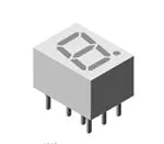
High Intensity Red Low Current 7-Segment Display
FEATURES
• 1500 μcd typical at 1 mA
• Very low power consumption
• Wide viewing angle
• Grey package surface
• Light intensity categorized at IF = 1 mA
• Material categorization: for definitions of
compliance please see www.vishay.com/doc?99912
19236
DESCRIPTION
APPLICATIONS
This series defines a new standard for low current displays.
It is a single digit 7-segment LED display utilizing AllnGaP
technology in color red.
The supreme light intensity allows applications under direct
sunlight or “black front” designs by using tinted filter glass
in front of the display.
Typical 1500 μcd at 1 mA is best in class performance for
applications with very limited power supply. The maximum
forward current of 10 mA is allowed for an ambient
temperature range of -40 °C to +85 °C without current
derating.
Due to the design of 10 mm displays, a certain amount of
cross-talk between segments is unavoidable. This light
leakage becomes more noticeable as the brightness of
the operated segments increases. However, higher
environmental illumination, or a partially transparent cover,
may reduce this effect. Therefore, it's important to consider
this phenomenon during design-in and to validate suitability
for the particular application and all its operation modes.
• Battery driven instruments
• Telecom devices
• Home appliances
• Instrumentation
• POS terminals
PRODUCT GROUP AND PACKAGE DATA
• Product group: display
• Package: 10 mm
• Product series: low current
• Angle of half intensity: ± 50°
PARTS TABLE
PART
COLOR
LUMINOUS INTENSITY
(μcd)
MIN.
TYP.
MAX.
WAVELENGTH
at
at FORWARD VOLTAGE at
(nm)
(V)
IF
IF
IF
(mA) MIN. TYP. MAX. (mA) MIN. TYP. MAX. (mA)
CIRCUITRY
TDSR1050
Red
280
-
3600
1
-
640
-
1
-
1.8
2.4
1
TDSR1050-IK
Red
1100
-
3600
1
-
640
-
1
-
1.8
2.4
1
Common anode
Common anode
TDSR1060
Red
280
-
3600
1
-
640
-
1
-
1.8
2.4
1
Common cathode
ABSOLUTE MAXIMUM RATINGS (Tamb = 25 °C, unless otherwise specified)
TDSR1050, TDSR1050-IK, TDSR1060
PARAMETER
SYMBOL
VALUE
Reverse voltage per segment
VR
5
V
DC forward current per segment
IF
10
mA
Peak forward current per segment
Power dissipation
TEST CONDITION
tp ≤ 10 μs, duty cycle 1/10
IFM
50
mA
Tamb ≤ 85 °C
PV
185
mW
Junction temperature
Operating temperature range
Storage temperature range
Soldering temperature
Thermal resistance LED junction to ambient
Rev. 1.5, 15-Nov-2021
UNIT
t ≤ 3 s, 2 mm below seating plane
Tj
105
°C
Tamb
-40 to +85
°C
Tstg
-40 to +85
°C
Tsd
260
°C
RthJA
100
K/W
Document Number: 81199
1
For technical questions, contact: LED@Vishay.com
THIS DOCUMENT IS SUBJECT TO CHANGE WITHOUT NOTICE. THE PRODUCTS DESCRIBED HEREIN AND THIS DOCUMENT
ARE SUBJECT TO SPECIFIC DISCLAIMERS, SET FORTH AT www.vishay.com/doc?91000
�TDSR1050, TDSR1060
www.vishay.com
Vishay Semiconductors
OPTICAL AND ELECTRICAL CHARACTERISTICS (Tamb = 25 °C, unless otherwise specified)
TDSR1050, TDSR1050-IK, TDSR1060, RED
PARAMETER
TEST CONDITION
PART
SYMBOL
MIN.
TYP.
MAX.
280
-
3600
1100
-
3600
280
-
3600
TDSR1050
Luminous intensity per segment (digit
average)
IF = 1 mA
TDSR1050-IK
IV
TDSR1060
UNIT
μcd
Dominant wavelength
IF = 1 mA
λd
-
640
-
nm
Peak wavelength
IF = 1 mA
λp
-
650
-
nm
Angle of half intensity
IF = 1 mA
ϕ
-
± 50
-
°
Forward voltage per segment or DP
IF = 1 mA
VF
-
1.8
2.4
V
Reverse voltage per segment or DP
VR = 6 V
IR
-
10
-
μA
TDSR1050,
TDSR1050-IK,
TDSR1060
LUMINOUS INTENSITY CLASSIFICATION
GROUP
LIGHT INTENSITY (μcd)
STANDARD
MIN.
MAX.
560
F
280
G
450
900
H
700
1400
I
1100
2200
K
1800
3600
L
2800
5600
Note
• The above type numbers represent the order groups which include only a few brightness groups. Only one group will be shipped in one tube
(there will be no mixing of two groups in one tube).
In order to ensure availability, single brightness groups will not be orderable.
TYPICAL CHARACTERISTICS (Tamb = 25 °C, unless otherwise specified)
0°
10°
20°
25
20
15
10
5
40°
1.0
0.9
50°
0.8
60°
70°
0.7
ϕ - Angular Displacement
30°
IV rel - Relative Luminous Intensity
IF - Forward Current (mA)
30
80°
0
0
18540
20
40
60
80 85
Tamb - Ambient Temperature (°C)
100
Fig. 1 - Forward Current vs. Ambient Temperature
Rev. 1.5, 15-Nov-2021
0.6
0.4
0.2
0
95 10082
Fig. 2 - Relative Luminous Intensity vs. Angular Displacement
Document Number: 81199
2
For technical questions, contact: LED@Vishay.com
THIS DOCUMENT IS SUBJECT TO CHANGE WITHOUT NOTICE. THE PRODUCTS DESCRIBED HEREIN AND THIS DOCUMENT
ARE SUBJECT TO SPECIFIC DISCLAIMERS, SET FORTH AT www.vishay.com/doc?91000
�TDSR1050, TDSR1060
www.vishay.com
Vishay Semiconductors
1.2
IV rel - Relative Luminous Intensity
IF - Forward Current (mA)
100
10
1
1
1.5
2
2.5
3
VF - Forward Voltage (V)
95 10878
Fig. 3 - Forward Current vs. Forward Voltage
IF = 10 mA
red
1.0
0.8
0.6
0.4
0.2
0.0
560 580 600 620 640 660 680 700 720
18541
λ - Wavelength (mm)
Fig. 6 - Relative Luminous Intensity vs. Ambient Temperature
IV rel - Relative Luminous Intensity
100
1
10
10
a
2
f
b
9
g
3
1
4
8
e
d
c
DP
5
0.1
0.1
1
10
7
1
2
3
4
5
6
7
8
9
10
g
f
A(C)
e
d
DP
c
A(C)
b
a
6
96 11678
100
IF - Forward Current (mA)
16120
Fig. 4 - Relative Luminous Intensity vs. Forward Current
Fig. 7 - TDSR10..
IV rel - Relative Luminous Intensity
1.6
red
IF = 1 mA
1.4
1.2
1.0
0.8
0.6
0.4
0.2
0
16119
0
10
20 30 40 50 60 70 80 90 100
Tamb - Ambient Temperature (°C)
Fig. 5 - Relative Luminous Intensity vs. Ambient Temperature
Rev. 1.5, 15-Nov-2021
Document Number: 81199
3
For technical questions, contact: LED@Vishay.com
THIS DOCUMENT IS SUBJECT TO CHANGE WITHOUT NOTICE. THE PRODUCTS DESCRIBED HEREIN AND THIS DOCUMENT
ARE SUBJECT TO SPECIFIC DISCLAIMERS, SET FORTH AT www.vishay.com/doc?91000
�TDSR1050, TDSR1060
www.vishay.com
Vishay Semiconductors
PACKAGE DIMENSIONS FOR TDSR10.. in millimeters
12.6 ± 0.2
10.7 ± 0.3
6.4 ± 0.1
7 ± 0.1
9.45 ± 0.1
0.3 ± 0.05
0.5 ± 0.05
7.62 ± 0.2
2.54 nom
4 x 2.54 = 10.16
6
10
Ø 1.2
0.9
technical drawings
according to DIN
specifications
10°
Drawing-No.: 6.544-5093.01-4
Issue: 2; 23.03.2012
95 11343
Rev. 1.5, 15-Nov-2021
Document Number: 81199
4
For technical questions, contact: LED@Vishay.com
THIS DOCUMENT IS SUBJECT TO CHANGE WITHOUT NOTICE. THE PRODUCTS DESCRIBED HEREIN AND THIS DOCUMENT
ARE SUBJECT TO SPECIFIC DISCLAIMERS, SET FORTH AT www.vishay.com/doc?91000
�Legal Disclaimer Notice
www.vishay.com
Vishay
Disclaimer
ALL PRODUCT, PRODUCT SPECIFICATIONS AND DATA ARE SUBJECT TO CHANGE WITHOUT NOTICE TO IMPROVE
RELIABILITY, FUNCTION OR DESIGN OR OTHERWISE.
Vishay Intertechnology, Inc., its affiliates, agents, and employees, and all persons acting on its or their behalf (collectively,
“Vishay”), disclaim any and all liability for any errors, inaccuracies or incompleteness contained in any datasheet or in any other
disclosure relating to any product.
Vishay makes no warranty, representation or guarantee regarding the suitability of the products for any particular purpose or
the continuing production of any product. To the maximum extent permitted by applicable law, Vishay disclaims (i) any and all
liability arising out of the application or use of any product, (ii) any and all liability, including without limitation special,
consequential or incidental damages, and (iii) any and all implied warranties, including warranties of fitness for particular
purpose, non-infringement and merchantability.
Statements regarding the suitability of products for certain types of applications are based on Vishay's knowledge of typical
requirements that are often placed on Vishay products in generic applications. Such statements are not binding statements
about the suitability of products for a particular application. It is the customer's responsibility to validate that a particular product
with the properties described in the product specification is suitable for use in a particular application. Parameters provided in
datasheets and / or specifications may vary in different applications and performance may vary over time. All operating
parameters, including typical parameters, must be validated for each customer application by the customer's technical experts.
Product specifications do not expand or otherwise modify Vishay's terms and conditions of purchase, including but not limited
to the warranty expressed therein.
Hyperlinks included in this datasheet may direct users to third-party websites. These links are provided as a convenience and
for informational purposes only. Inclusion of these hyperlinks does not constitute an endorsement or an approval by Vishay of
any of the products, services or opinions of the corporation, organization or individual associated with the third-party website.
Vishay disclaims any and all liability and bears no responsibility for the accuracy, legality or content of the third-party website
or for that of subsequent links.
Except as expressly indicated in writing, Vishay products are not designed for use in medical, life-saving, or life-sustaining
applications or for any other application in which the failure of the Vishay product could result in personal injury or death.
Customers using or selling Vishay products not expressly indicated for use in such applications do so at their own risk. Please
contact authorized Vishay personnel to obtain written terms and conditions regarding products designed for such applications.
No license, express or implied, by estoppel or otherwise, to any intellectual property rights is granted by this document or by
any conduct of Vishay. Product names and markings noted herein may be trademarks of their respective owners.
© 2022 VISHAY INTERTECHNOLOGY, INC. ALL RIGHTS RESERVED
Revision: 01-Jan-2022
1
Document Number: 91000
�