TFPT
www.vishay.com
Vishay
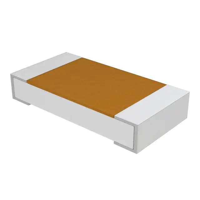
SMD PTC - Nickel Thin Film Linear Thermistors
FEATURES
• Alumina substrate base with nickel based PTC
thin film element
Available
• 0402, 0603, 0805, and 1206 sizes available
• Available in tape and reel packaging
• Standard R25 tolerances: ± 0.5 %, ± 1 %, ± 5 %
• Operation range -55 °C to +150 °C
Available
• High stability over the entire temperature range
• cULus recognized, file E148885
(UL category XGPU2 / XGPU8)
• AEC-Q200 qualified (grade 1), except TFPT0402
• Material categorization: for definitions of compliance
please see www.vishay.com/doc?99912
ADDITIONAL RESOURCES
Note
* This datasheet provides information about parts that are
RoHS-compliant and / or parts that are non RoHS-compliant. For
example, parts with lead (Pb) terminations are not RoHS-compliant.
Please see the information / tables in this datasheet for details
Design Tools
APPLICATIONS
Temperature compensation and sensing in
• Automotive
• Motor drives
• Lighting LED drivers
• Test and measuring equipment
• Air-flow sensor
QUICK REFERENCE DATA
PARAMETER
DESCRIPTION
Resistance value at 25 °C (2)
Tolerance on R25-value (2)
TCR at 25 °C
Tolerance on TCR at 25 °C (1)
Operating temperature range:
at rated power
at zero dissipation (4)
Dissipation factor (for information only) (5)
Maximum rated power at 70 °C (P70) (5)
Maximum working voltage RCWV (3)
Climatic category (LCT/UCT/days)
Weight
Failure rate FITobserved
VALUE
TFPT0402
5
± 25
TFPT0603
100 to 1K
TFPT0805
100 to 5K
± 0.5; ± 1; ± 5
TFPT1206
100 to 10K
4110
± 400
1.8
75
30
0.65
2
%
ppm/K
-55 to +70
-55 to +150
0.8
100 (6)
1.2
UNIT
°C
2.3
100
40
4
125
50
5.5
10
55/150/56
mW/K
mW
V
mg
0.1 x 10⁻⁹/h
Notes
(1) Contact Vishay if closer TCR lot tolerance is desired
(2) Other R -values and tolerances are available upon request
25
(3) Rated continuous working voltage is maximum working voltage or P
70 x R whichever is less
(4) Zero power or zero dissipation is considered as measuring power max. 1 % of rated power P
70
(5) Please refer to APPLICATION INFORMATION
(6) Power levels are depending on way of mounting and substrates used. Higher power up to 200 mW at 25 °C (P ) can be tolerated on uniform
25
layer TFPT0402 5R
APPLICATION INFORMATION
When the resistor dissipates power, a temperature rise above the ambient temperature occurs, dependent on the thermal
resistance of the assembled resistor together with the printed circuit board. The rated dissipation applies only if the permitted
film temperature of 150 °C is not exceeded.
Please consider the application note “Thermal Management in Surface-Mounted Resistor Applications”
(www.vishay.com/doc?28844) for information on the general nature of thermal resistance.
The TFPT0402 uniform layer linear thermistor with low resistance value can be used as an air-flow sensor in a controlled power
mode where nickel film temperature changes can be related to air-flow speed.
Revision: 14-Jan-2020
Document Number: 33017
1
For technical questions, contact: nlr@vishay.com
THIS DOCUMENT IS SUBJECT TO CHANGE WITHOUT NOTICE. THE PRODUCTS DESCRIBED HEREIN AND THIS DOCUMENT
ARE SUBJECT TO SPECIFIC DISCLAIMERS, SET FORTH AT www.vishay.com/doc?91000
�TFPT
www.vishay.com
Vishay
STANDARD RESISTANCE VALUES at 25 °C in
100
120
150
180
220
270
330
390
470
560
680
820
1.0K
1.2K
1.5K
Note
• Rated continuous working voltage is maximum working voltage or
1.8K
2.2K
2.7K
3.3K
3.9K
4.7K
5.0K
5.6K
6.8K
8.2K
10.0K
P 70 x R whichever is less
GLOBAL PART NUMBER INFORMATION
Global Part Numbering: TFPT1206L1002FM (preferred part number format)
T
F
P
T
1
2
0
6
L
1
0
0
2
F
M
GLOBAL MODEL
CHARACTERISTIC
RESISTANCE VALUE
TOLERANCE CODE
PACKAGING
TFPT0402
TFPT0603
TFPT0805
TFPT1206
L = linear
U = uniform linear (0402)
1002 = 10K
0050 = 5R (0402)
D = ± 0.5 %
F=±1%
J=±5%
V = ± 25 % (0402)
L = lead (Pb)-free, T/R (10 000 pcs) 0402
M = lead (Pb)-free, T/R (5000 pcs)
V = lead (Pb)-free, T/R (1000 pcs)
DIMENSIONS in millimeters
Z = tin / lead, T/R (5000 pcs)
Y = tin / lead, T/R (1000 pcs)
CONSTRUCTION
A
Overcoating
D
Thermistor
C
B
E
PART NUMBER
TFPT 0402
TFPT 0603
TFPT 0805
TFPT 1206
A
1.00
± 0.05
1.55
± 0.10
2.00
± 0.15
3.05
± 0.15
B
0.50
± 0.05
0.80
± 0.10
1.25
± 0.15
1.50
± 0.15
C
0.35
± 0.07
0.45
± 0.10
0.45
± 0.10
0.55
± 0.10
D
0.20
± 0.10
0.30
± 0.20
0.40
± 0.20
0.50
± 0.25
Alumina substrate
E
0.20
± 0.10
0.30
± 0.20
0.40
± 0.20
0.50
± 0.25
Inner electrode
Nickel barrier
Solderable coating
TESTS AND REQUIREMENTS (except TFPT0402)
TEST
High temperature exposure (storage)
Temperature cycling
Biased humidity
Operational life
Mechanical shock and vibration
Resistance to soldering heat
ESD (2)
Board flex
Terminal strength
CONDITIONS (1)
AEC-Q200, 1000 h at 150 °C
AEC-Q200, 1000 cycles -55 °C / +125 °C
1000 h, 1 mA biased at 85 °C / 85 % RH
1000 h, 1 mA biased at 40 °C / 95 % RH
1000 h, P70 max biased at 85 °C
MIL-STD 202, method 213 - 204
MIL-STD 202, method 210, solder bath dipping 10 s at 260°C
AEC-Q200-002, HBM (CD) 0.5 kV (0603), 1.0 kV (0805), 1.0 kV (1206)
AEC-Q200-005, 2 mm during 60 s
AEC-Q200-006, shear test 17.7 N during 60 s
REQUIREMENTS
MAX. |R25/R25|
0.25 %
0.25 %
0.25 %
0.25 %
0.25 %
0.50 %
0.25 %
0.25 %
0.25 %
0.25 %
Notes
(1) Environmental performance specifications use test procedures as outlined in MIL-R23648D, MIL-STD 202 and AEC-Q200
(2) TFPTs are ESD sensitive
Revision: 14-Jan-2020
Document Number: 33017
2
For technical questions, contact: nlr@vishay.com
THIS DOCUMENT IS SUBJECT TO CHANGE WITHOUT NOTICE. THE PRODUCTS DESCRIBED HEREIN AND THIS DOCUMENT
ARE SUBJECT TO SPECIFIC DISCLAIMERS, SET FORTH AT www.vishay.com/doc?91000
�TFPT
www.vishay.com
Vishay
AGENCY APPROVALS (except TFPT0402)
• cUL certificate
• ULus certificate
Note
• Agency approval documents, please see: www.vishay.com/ppg?33017&documents
AVERAGE RATIO R/R25 TFPT ALL SIZES AND VALUES
TEMP.
R/R25
TEMP.
R/R25
TEMP.
R/R25
TEMP.
R/R25
TEMP.
R/R25
TEMP.
R/R25
-20
0.825
20
0.980
60
1.150
100
1.337
140
1.541
-19
0.828
21
0.984
61
1.155
101
1.342
141
1.547
-18
0.832
22
0.988
62
1.159
102
1.347
142
1.552
-17
0.836
23
0.992
63
1.164
103
1.352
143
1.557
-16
0.839
24
0.996
64
1.168
104
1.357
144
1.563
-55
0.702
-15
0.843
25
1.000
65
1.173
105
1.362
145
1.568
-54
0.705
-14
0.847
26
1.004
66
1.177
106
1.367
146
1.574
-53
0.708
-13
0.851
27
1.008
67
1.182
107
1.372
147
1.579
-52
0.712
-12
0.854
28
1.012
68
1.186
108
1.377
148
1.584
-51
0.715
-11
0.858
29
1.017
69
1.191
109
1.382
149
1.590
-50
0.719
-10
0.862
30
1.021
70
1.196
110
1.387
150
1.595
-49
0.722
-9
0.866
31
1.025
71
1.200
111
1.392
-48
0.725
-8
0.869
32
1.029
72
1.205
112
1.397
-47
0.729
-7
0.873
33
1.033
73
1.209
113
1.402
-46
0.732
-6
0.877
34
1.037
74
1.214
114
1.407
-45
0.736
-5
0.881
35
1.042
75
1.219
115
1.412
-44
0.739
-4
0.885
36
1.046
76
1.223
116
1.417
-43
0.743
-3
0.889
37
1.050
77
1.228
117
1.422
-42
0.746
-2
0.892
38
1.054
78
1.232
118
1.427
-41
0.749
-1
0.896
39
1.059
79
1.237
119
1.432
-40
0.753
0
0.900
40
1.063
80
1.242
120
1.437
-39
0.756
1
0.904
41
1.067
81
1.246
121
1.442
-38
0.760
2
0.908
42
1.071
82
1.251
122
1.448
-37
0.763
3
0.912
43
1.076
83
1.256
123
1.453
-36
0.767
4
0.916
44
1.080
84
1.261
124
1.458
-35
0.771
5
0.920
45
1.084
85
1.265
125
1.463
-34
0.774
6
0.924
46
1.089
86
1.270
126
1.468
-33
0.778
7
0.927
47
1.093
87
1.275
127
1.473
-32
0.781
8
0.931
48
1.097
88
1.280
128
1.478
-31
0.785
9
0.935
49
1.102
89
1.284
129
1.484
-30
0.788
10
0.939
50
1.106
90
1.289
130
1.489
-29
0.792
11
0.943
51
1.110
91
1.294
131
1.494
-28
0.796
12
0.947
52
1.115
92
1.299
132
1.499
-27
0.799
13
0.951
53
1.119
93
1.303
133
1.505
-26
0.803
14
0.955
54
1.124
94
1.308
134
1.510
-25
0.806
15
0.959
55
1.128
95
1.313
135
1.515
-24
0.810
16
0.963
56
1.133
96
1.318
136
1.520
-23
0.814
17
0.967
57
1.137
97
1.323
137
1.526
-22
0.817
18
0.971
58
1.141
98
1.328
138
1.531
-21
0.821
19
0.975
59
1.146
99
1.333
139
1.536
Revision: 14-Jan-2020
Document Number: 33017
3
For technical questions, contact: nlr@vishay.com
THIS DOCUMENT IS SUBJECT TO CHANGE WITHOUT NOTICE. THE PRODUCTS DESCRIBED HEREIN AND THIS DOCUMENT
ARE SUBJECT TO SPECIFIC DISCLAIMERS, SET FORTH AT www.vishay.com/doc?91000
�TFPT
www.vishay.com
Vishay
RATIO FORMULA
RT = R25 x (9.0014 x 10-1 + 3.87235 x 10⁻³ (°C)-1 x T + 4.86825 x 10⁻⁶ (°C)-2 x T2 + 1.37559 x 10⁻⁹ (°C)-3 x T3)
T(°C) = 28.54 x (RT/R25)3 - 158.5 x (RT/R25)2 + 474.8 x (RT/R25) - 319.85)
RATIO TOLERANCE EXAMPLES:
RATIO TOLERANCES
LOW TEMP.
HIGH TEMP.
TOL.
-55 °C
+150 °C
±4%
-40 °C
+125 °C
±3%
-20 °C
+85 °C
±2%
0 °C
+55 °C
±1%
+12 °C
+40 °C
± 0.5 %
At 40 °C, ratio = 1.063 ± 0.5 % (0.005)
so, ratio = 1.058 to 1.068
At 125 °C, ratio = 1.460 ± 3 % (0.044)
so, ratio = 1.416 to 1.504
At intermediate temperatures, the ratios can be gradually
adapted, for example at 105 °C the ratio tolerance will be
± 2.5 %.
For total resistance tolerance, the specific R25 tolerance
needs to be multiplied with the ratio tolerance, for example
a 100R 1 % at 25 °C will have a maximum resistance at
125 °C of 100R x 1.463 x 1.03 x 1.01 = 152.2 .
RATIO RT/R25
TCR TYPICAL VALUE
Axis Title
Axis Title
1.7
4800
10000
4600
Max.
1.5
4500
1st line
2nd line
1000
1.2
1.1
1.0
100
4400
4200
4100
4000
0.9
3900
0.8
3800
0.7
1000
4300
1st line
2nd line
Min.
1.3
2nd line
TCR (ppm/K)
1.4
2nd line
Ratio
10000
4700
1.6
100
3700
10
0.6
-75 -50 -25
0
25
50
10
3600
75 100 125 150
-75 -50 -25
Temperature (°C)
0
25
50
75 100 125 150 175
Temperature (°C)
POWER DERATING
Axis Title
110
10000
100
90
1000
70
1st line
2nd line
2nd line
Power of P70 (%)
80
60
50
40
100
30
20
10
10
0
-75 -50 -25
0
25
50
75 100 125 150 175
Temperature (°C)
Note
• Zero power is considered as measuring power max. 1 % of rated
power P70
Revision: 14-Jan-2020
Document Number: 33017
4
For technical questions, contact: nlr@vishay.com
THIS DOCUMENT IS SUBJECT TO CHANGE WITHOUT NOTICE. THE PRODUCTS DESCRIBED HEREIN AND THIS DOCUMENT
ARE SUBJECT TO SPECIFIC DISCLAIMERS, SET FORTH AT www.vishay.com/doc?91000
�Legal Disclaimer Notice
www.vishay.com
Vishay
Disclaimer
ALL PRODUCT, PRODUCT SPECIFICATIONS AND DATA ARE SUBJECT TO CHANGE WITHOUT NOTICE TO IMPROVE
RELIABILITY, FUNCTION OR DESIGN OR OTHERWISE.
Vishay Intertechnology, Inc., its affiliates, agents, and employees, and all persons acting on its or their behalf (collectively,
“Vishay”), disclaim any and all liability for any errors, inaccuracies or incompleteness contained in any datasheet or in any other
disclosure relating to any product.
Vishay makes no warranty, representation or guarantee regarding the suitability of the products for any particular purpose or
the continuing production of any product. To the maximum extent permitted by applicable law, Vishay disclaims (i) any and all
liability arising out of the application or use of any product, (ii) any and all liability, including without limitation special,
consequential or incidental damages, and (iii) any and all implied warranties, including warranties of fitness for particular
purpose, non-infringement and merchantability.
Statements regarding the suitability of products for certain types of applications are based on Vishay's knowledge of typical
requirements that are often placed on Vishay products in generic applications. Such statements are not binding statements
about the suitability of products for a particular application. It is the customer's responsibility to validate that a particular product
with the properties described in the product specification is suitable for use in a particular application. Parameters provided in
datasheets and / or specifications may vary in different applications and performance may vary over time. All operating
parameters, including typical parameters, must be validated for each customer application by the customer's technical experts.
Product specifications do not expand or otherwise modify Vishay's terms and conditions of purchase, including but not limited
to the warranty expressed therein.
Hyperlinks included in this datasheet may direct users to third-party websites. These links are provided as a convenience and
for informational purposes only. Inclusion of these hyperlinks does not constitute an endorsement or an approval by Vishay of
any of the products, services or opinions of the corporation, organization or individual associated with the third-party website.
Vishay disclaims any and all liability and bears no responsibility for the accuracy, legality or content of the third-party website
or for that of subsequent links.
Except as expressly indicated in writing, Vishay products are not designed for use in medical, life-saving, or life-sustaining
applications or for any other application in which the failure of the Vishay product could result in personal injury or death.
Customers using or selling Vishay products not expressly indicated for use in such applications do so at their own risk. Please
contact authorized Vishay personnel to obtain written terms and conditions regarding products designed for such applications.
No license, express or implied, by estoppel or otherwise, to any intellectual property rights is granted by this document or by
any conduct of Vishay. Product names and markings noted herein may be trademarks of their respective owners.
© 2022 VISHAY INTERTECHNOLOGY, INC. ALL RIGHTS RESERVED
Revision: 01-Jan-2022
1
Document Number: 91000
�


 工商网监
湘ICP备2023018690号
工商网监
湘ICP备2023018690号
