TFPTL
www.vishay.com
Vishay
Radial Leaded PTC - Nickel Thin Film Linear Thermistors
FEATURES
•
•
•
•
•
Nickel thin film PTC element
High stability over the entire temperature range
cUL recognized component: File E148885
Epoxy coated UL 94 V-0 approved
Material categorization: For definitions of compliance
please see www.vishay.com/doc?99912
APPLICATIONS
Temperature measurement, sensing, compensation, and
control in industrial and consumer applications. For
on-board or remote sensing.
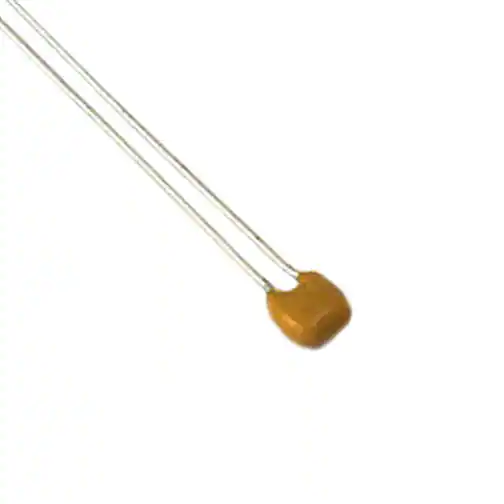
DESCRIPTION
MARKING
These thermistors are based on a Nickel thin film resistor
technology as thermal sensitive material. The device
consists of a thin film ceramic chip with two tinned copper
clad steel wire leads.
The thermistors are laser marked with value and tolerance
reference on an epoxy based coating.
(Example: 102F = 10 x 102 = 1000 Ω 1 %)
MOUNTING
By soldering or welding in any position.
QUICK REFERENCE DATA
PARAMETER
DESCRIPTION
Resistance value at 25 °C (2)
Tolerance on R25-value (2)
TCR at 25 °C
Tolerance on TCR at 25 °C (1)
Operating temperature range:
at rated power
at zero dissipation
Response time (in oil)
Dissipation factor δ (for information only)
Maximum rated power at 70 °C (P70)
Maximum working voltage RCWV (3)
Climatic category (LCT/UCT/days)
Weight
VALUE
TFPTL10
100 to 1K
UNIT
TFPTL15
100 to 5K
Ω
%
ppm/K
ppm/K
± 1; ± 5
4110
± 400
-55 to +70
-55 to +150
°C
≈ 1.1
2.9
75
30
≈ 1.6
3.4
100
40
s
mW/K
mW
V
g
55/150/56
0.12
0.14
Notes
(1) Contact Vishay if closer TCR lot tolerance is desired
(2) Other R -values and tolerances are available upon request
25
(3) Rated continuous working voltage is maximum working voltage or P
70 x R , whichever is less
STANDARD RESISTANCE VALUES at 25 °C in Ω
100
120
150
180
220
270
330
390
470
560
680
820
1K
1.2K
1.5K
1.8K
2.2K
2.7K
3.3K
3.9K
4.7K
5.0K
Note
• Other R25-values and tolerances are available upon request
GLOBAL PART NUMBER INFORMATION
Global Part Numbering: TFPTL10L1001FL2B
T
F
P
T
L
PRODUCT
TYPE
SIZE
CHARACTERISTICS
TFPT
Leaded
10
15
L = Linear
Revision: 25-Oct-11
1
0
RESISTANCE
VALUE
1000 = 100R
1001 = 1K
5001 = 5K
L
1
0
0
1
F
TOLERANCE
LEAD
CONFIGURATION
F=±1%
J=±5%
L2
H5
L
2
B
PACKAGING
B = Bulk (500 pieces)
U = Ammopack (2500 pieces)
T = T/R (4000 pieces)
Document Number: 33027
1
For technical questions, contact: nlr@vishay.com
THIS DOCUMENT IS SUBJECT TO CHANGE WITHOUT NOTICE. THE PRODUCTS DESCRIBED HEREIN AND THIS DOCUMENT
ARE SUBJECT TO SPECIFIC DISCLAIMERS, SET FORTH AT www.vishay.com/doc?91000
�TFPTL
www.vishay.com
Vishay
DIMENSIONS
Wb
SH
T
Wb
471J
H
102F
H
SH
L
L
d
F
F
L2
H5
Component outline for
lead spacing 2.5 mm ± 0.8 mm
(straight leads)
Component outline for
lead spacing 5.0 mm ± 0.8 mm
(flat bent leads)
TFPTL DIMENSIONS in millimeters
SIZE L10
SIZE L15
L2
H5
Wbmax.
L2
H5
3.6
Hmax.
4.0
3.5
SHmax. (seating height)
3.8
5.0
6.2
5.2
d
6.5
0.5 ± 10 %
L
25 min.
F
2.5 ± 0.8
Tmax.
5.0 ± 0.8
2.5 ± 0.8
2.2
5.0 ± 0.8
2.4
Notes
• Bulk packed types have a standard lead length L = 25 mm minimum
• Thickness is defined as “T”
Power in % of P70
Power Derating
110
100
90
80
70
60
50
40
30
20
10
0
- 75
- 50
- 25
0
25
50
75
100
125
150
175
Temperature in °C
Note
• Zero power is considered as measuring power max. 1 % of rated power P70
Revision: 25-Oct-11
Document Number: 33027
2
For technical questions, contact: nlr@vishay.com
THIS DOCUMENT IS SUBJECT TO CHANGE WITHOUT NOTICE. THE PRODUCTS DESCRIBED HEREIN AND THIS DOCUMENT
ARE SUBJECT TO SPECIFIC DISCLAIMERS, SET FORTH AT www.vishay.com/doc?91000
�TFPTL
www.vishay.com
Vishay
PERFORMANCE
MAXIMUM ΔR25/R25 (1)
± 0.25 %
± 0.3 %
± 0.2 %
± 0.2 %
± 0.2 %
± 0.2 %
± 0.2 %
± 0.25 %
TEST
Storage dry heat (5000 h at 125 °C)
High temperature exposure (1000 h at 150 °C)
Damp heat steady state, unloaded (1344 h at 40 °C/95 % RH)
Thermal cycling (15 min at -55 °C, 15 min at 150 °C, 100 cycles)
Thermal cycling (15 min at -55 °C, 15 min at 125 °C, 1000 cycles)
Short time overload (2.5 x P70 for 60s at 70 °C)
Long term dissipation (1000 h rated power at 70 °C)
Resistance to soldering heat (10 s at 260 °C)
Note
(1) TFPTs are ESD sensitive
AVERAGE RATIO R/R25 TFPTL ALL SIZES AND VALUES
TEMP.
R/R25
-55
-54
-53
-52
-51
-50
-49
-48
-47
-46
-45
-44
-43
-42
-41
-40
-39
-38
-37
-36
-35
-34
-33
-32
-31
-30
-29
-28
-27
-26
-25
-24
-23
-22
-21
0.702
0.705
0.708
0.712
0.715
0.719
0.722
0.725
0.729
0.732
0.736
0.739
0.743
0.746
0.749
0.753
0.756
0.760
0.763
0.767
0.771
0.774
0.778
0.781
0.785
0.788
0.792
0.796
0.799
0.803
0.806
0.810
0.814
0.817
0.821
Revision: 25-Oct-11
TEMP.
-20
-19
-18
-17
-16
-15
-14
-13
-12
-11
-10
-9
-8
-7
-6
-5
-4
-3
-2
-1
0
1
2
3
4
5
6
7
8
9
10
11
12
13
14
15
16
17
18
19
R/R25
0.825
0.828
0.832
0.836
0.839
0.843
0.847
0.851
0.854
0.858
0.862
0.866
0.869
0.873
0.877
0.881
0.885
0.889
0.892
0.896
0.900
0.904
0.908
0.912
0.916
0.920
0.924
0.927
0.931
0.935
0.939
0.943
0.947
0.951
0.955
0.959
0.963
0.967
0.971
0.975
TEMP.
20
21
22
23
24
25
26
27
28
29
30
31
32
33
34
35
36
37
38
39
40
41
42
43
44
45
46
47
48
49
50
51
52
53
54
55
56
57
58
59
R/R25
0.980
0.984
0.988
0.992
0.996
1.000
1.004
1.008
1.012
1.017
1.021
1.025
1.029
1.033
1.037
1.042
1.046
1.050
1.054
1.059
1.063
1.067
1.071
1.076
1.080
1.084
1.089
1.093
1.097
1.102
1.106
1.110
1.115
1.119
1.124
1.128
1.133
1.137
1.141
1.146
TEMP.
60
61
62
63
64
65
66
67
68
69
70
71
72
73
74
75
76
77
78
79
80
81
82
83
84
85
86
87
88
89
90
91
92
93
94
95
96
97
98
99
R/R25
1.150
1.155
1.159
1.164
1.168
1.173
1.177
1.182
1.186
1.191
1.196
1.200
1.205
1.209
1.214
1.219
1.223
1.228
1.232
1.237
1.242
1.246
1.251
1.256
1.261
1.265
1.270
1.275
1.280
1.284
1.289
1.294
1.299
1.303
1.308
1.313
1.318
1.323
1.328
1.333
TEMP.
100
101
102
103
104
105
106
107
108
109
110
111
112
113
114
115
116
117
118
119
120
121
122
123
124
125
126
127
128
129
130
131
132
133
134
135
136
137
138
139
R/R25
1.337
1.342
1.347
1.352
1.357
1.362
1.367
1.372
1.377
1.382
1.387
1.392
1.397
1.402
1.407
1.412
1.417
1.422
1.427
1.432
1.437
1.442
1.448
1.453
1.458
1.463
1.468
1.473
1.478
1.484
1.489
1.494
1.499
1.505
1.510
1.515
1.520
1.526
1.531
1.536
TEMP.
140
141
142
143
144
145
146
147
148
149
150
R/R25
1.541
1.547
1.552
1.557
1.563
1.568
1.574
1.579
1.584
1.590
1.595
Document Number: 33027
3
For technical questions, contact: nlr@vishay.com
THIS DOCUMENT IS SUBJECT TO CHANGE WITHOUT NOTICE. THE PRODUCTS DESCRIBED HEREIN AND THIS DOCUMENT
ARE SUBJECT TO SPECIFIC DISCLAIMERS, SET FORTH AT www.vishay.com/doc?91000
�TFPTL
www.vishay.com
Vishay
RATIO FORMULA
RT = R25 x (9.0014 x 10-1 + 3.87235 x 10⁻³ (°C)-1 x T + 4.86825 x 10⁻⁶ (°C)-2 x T2 + 1.37559 x 10⁻⁹ (°C)-3 x T3)
T(°C) = 28.54 x (RT/R25)3 - 158.5 x (RT/R25)2 + 474.8 x (RT/R25) - 319.85)
Ratio Tolerance Examples:
RATIO TOLERANCES
LOW TEMP.
HIGH TEMP.
TOL.
-55 °C
+150 °C
±4%
-40 °C
+125 °C
±3%
-20 °C
+85 °C
±2%
0 °C
+55 °C
±1%
+12 °C
+40 °C
± 0.5 %
At 40 °C, ratio = 1.063 ± 0.5 % (0.005)
so, ratio = 1.058 to 1.068
At 125 °C, ratio = 1.460 ± 3 % (0.044)
so, ratio = 1.416 to 1.504
Ratio RT/R25
1.7
1.6
1.5
Max.
1.4
1.3
Ratio
Min.
1.2
1.1
1.0
Min.
0.9
Max.
0.8
0.7
0.6
- 75
- 50
- 25
0
25
50
75
100
125
150
75
100
125
150
Temperature in °C
TCR Typical Value
4800
4700
4600
TCR in ppm/K
4500
4400
4300
4200
4100
4000
3900
3800
3700
3600
- 75
- 50
- 25
0
25
50
Temperature in °C
Revision: 25-Oct-11
Document Number: 33027
4
For technical questions, contact: nlr@vishay.com
THIS DOCUMENT IS SUBJECT TO CHANGE WITHOUT NOTICE. THE PRODUCTS DESCRIBED HEREIN AND THIS DOCUMENT
ARE SUBJECT TO SPECIFIC DISCLAIMERS, SET FORTH AT www.vishay.com/doc?91000
�Legal Disclaimer Notice
www.vishay.com
Vishay
Disclaimer
ALL PRODUCT, PRODUCT SPECIFICATIONS AND DATA ARE SUBJECT TO CHANGE WITHOUT NOTICE TO IMPROVE
RELIABILITY, FUNCTION OR DESIGN OR OTHERWISE.
Vishay Intertechnology, Inc., its affiliates, agents, and employees, and all persons acting on its or their behalf (collectively,
“Vishay”), disclaim any and all liability for any errors, inaccuracies or incompleteness contained in any datasheet or in any other
disclosure relating to any product.
Vishay makes no warranty, representation or guarantee regarding the suitability of the products for any particular purpose or
the continuing production of any product. To the maximum extent permitted by applicable law, Vishay disclaims (i) any and all
liability arising out of the application or use of any product, (ii) any and all liability, including without limitation special,
consequential or incidental damages, and (iii) any and all implied warranties, including warranties of fitness for particular
purpose, non-infringement and merchantability.
Statements regarding the suitability of products for certain types of applications are based on Vishay's knowledge of typical
requirements that are often placed on Vishay products in generic applications. Such statements are not binding statements
about the suitability of products for a particular application. It is the customer's responsibility to validate that a particular product
with the properties described in the product specification is suitable for use in a particular application. Parameters provided in
datasheets and / or specifications may vary in different applications and performance may vary over time. All operating
parameters, including typical parameters, must be validated for each customer application by the customer's technical experts.
Product specifications do not expand or otherwise modify Vishay's terms and conditions of purchase, including but not limited
to the warranty expressed therein.
Hyperlinks included in this datasheet may direct users to third-party websites. These links are provided as a convenience and
for informational purposes only. Inclusion of these hyperlinks does not constitute an endorsement or an approval by Vishay of
any of the products, services or opinions of the corporation, organization or individual associated with the third-party website.
Vishay disclaims any and all liability and bears no responsibility for the accuracy, legality or content of the third-party website
or for that of subsequent links.
Except as expressly indicated in writing, Vishay products are not designed for use in medical, life-saving, or life-sustaining
applications or for any other application in which the failure of the Vishay product could result in personal injury or death.
Customers using or selling Vishay products not expressly indicated for use in such applications do so at their own risk. Please
contact authorized Vishay personnel to obtain written terms and conditions regarding products designed for such applications.
No license, express or implied, by estoppel or otherwise, to any intellectual property rights is granted by this document or by
any conduct of Vishay. Product names and markings noted herein may be trademarks of their respective owners.
© 2022 VISHAY INTERTECHNOLOGY, INC. ALL RIGHTS RESERVED
Revision: 01-Jan-2022
1
Document Number: 91000
�