TH3
www.vishay.com
Vishay Sprague
Solid Tantalum Surface Mount Capacitors
TANTAMOUNT™ Molded Case, HI-TMP®
High Temperature 150 °C, Automotive Grade
FEATURES
• Operating temperature up to 150 °C with 50 %
voltage derating
• AEC-Q200 qualified
• 100 % surge current tested
Available
(B, C, D, E case sizes)
Available
• RoHS-compliant terminations available:
matte tin (all cases), gold (A, C, D, and E cases)
• Standard EIA 535BAAC case size (A through E)
• Compliant terminations
Available
• Moisture sensitivity level 1
• Material categorization: for definitions of compliance
please see www.vishay.com/doc?99912
LINKS TO ADDITIONAL RESOURCES
3D 3D
3D Models
Calculators
Related
Documents
Infographics
Did You
Know?
Technical
Notes
Note
* This datasheet provides information about parts that are
RoHS-compliant and / or parts that are non RoHS-compliant. For
example, parts with lead (Pb) terminations are not RoHS-compliant.
Please see the information / tables in this datasheet for details
APPLICATIONS
PERFORMANCE / ELECTRICAL
CHARACTERISTICS
• Automotive
• Industrial
• High temperature sensors
www.vishay.com/doc?40215
Operating Temperature: -55 °C to +150 °C
Capacitance Range: 0.33 μF to 220 μF
Capacitance Tolerance: ± 10 %, ± 20 %
Voltage Rating: 6.3 VDC to 50 VDC
Note
• For recommended voltage derating guidelines see “Typical
Performance Characteristics”
ORDERING INFORMATION
TH3
D
106
K
035
C
0700
TYPE
CASE
CODE
CAPACITANCE
CAPACITANCE
TOLERANCE
DC VOLTAGE
RATING AT +85 °C
TERMINATION AND
PACKAGING
ESR
See
Ratings
and Case
Codes
table.
This is expressed in
picofarads. The first
two digits are the
significant figures.
The third is the
number of zeros
to follow.
K = ± 10 %
M = ± 20 %
This is expressed in V.
To complete the
three-digit block, zeros
precede the voltage
rating. A decimal point
is indicated by an “R”.
(6R3 = 6.3 V)
Gold
A = 7" (178 mm) reel
B = 13" (330 mm) reel
Maximum
100 kHz ESR
0500 = 500 mΩ
5000 = 5.0 Ω
10R0 = 10.0 Ω
Matte tin
C = 7" (178 mm) reel
D = 13" (330 mm) reel
V = 7" (178 mm) reel,
dry pack
U = 13" (330 mm) reel,
dry pack
Tin / lead
E = 7" (178 mm) reel
F = 13" (330 mm) reel
T = 7" (178 mm) reel,
dry pack
W = 13" (330 mm) reel,
dry pack
Notes
• We reserve the right to supply higher voltage ratings and tighter capacitance tolerance capacitors in the same case size. Voltage
substitutions will be marked with the higher voltage rating
• Dry pack as specified in J-STD-033
Revision: 17-Oct-2022
Document Number: 40084
1
For technical questions, contact: tantalum@vishay.com
THIS DOCUMENT IS SUBJECT TO CHANGE WITHOUT NOTICE. THE PRODUCTS DESCRIBED HEREIN AND THIS DOCUMENT
ARE SUBJECT TO SPECIFIC DISCLAIMERS, SET FORTH AT www.vishay.com/doc?91000
�TH3
www.vishay.com
Vishay Sprague
DIMENSIONS in inches [millimeters]
L
W
H
TW
Glue Pad
TH (MIN.)
P
Glue Pad
CASE CODE
EIA SIZE
L
W
H
P
TW
TH (MIN.)
A
3216-18
B
3528-21
C
6032-28
D
7343-31
E
7343-43
0.126 ± 0.008
[3.2 ± 0.20]
0.138 ± 0.008
[3.5 ± 0.20]
0.236 ± 0.012
[6.0 ± 0.30]
0.287 ± 0.012
[7.3 ± 0.30]
0.287 ± 0.012
[7.3 ± 0.30]
0.063 ± 0.008
[1.6 ± 0.20]
0.110 ± 0.008
[2.8 ± 0.20]
0.126 ± 0.012
[3.2 ± 0.30]
0.169 ± 0.012
[4.3 ± 0.30]
0.169 ± 0.012
[4.3 ± 0.30]
0.063 ± 0.008
[1.6 ± 0.20]
0.075 ± 0.008
[1.9 ± 0.20]
0.098 ± 0.012
[2.5 ± 0.30]
0.110 ± 0.012
[2.8 ± 0.30]
0.157 ± 0.012
[4.0 ± 0.30]
0.031 ± 0.012
[0.80 ± 0.30]
0.031 ± 0.012
[0.80 ± 0.30]
0.051 ± 0.012
[1.3 ± 0.30]
0.051 ± 0.012
[1.3 ± 0.30]
0.051 ± 0.012
[1.3 ± 0.30]
0.047 ± 0.004
[1.2 ± 0.10]
0.087 ± 0.004
[2.2 ± 0.10]
0.087 ± 0.004
[2.2 ± 0.10]
0.094 ± 0.004
[2.4 ± 0.10]
0.094 ± 0.004
[2.4 ± 0.10]
0.028
[0.70]
0.028
[0.70]
0.039
[1.0]
0.039
[1.0]
0.039
[1.0]
35 V
A (11.0)
50 V
C (3.3)
Note
• Glue pad (non-conductive, part of molded case) is dedicated for glue attachment (as user option)
RATINGS AND CASE CODES
μF
0.33
0.47
0.68
6.3 V
10 V
16 V
20 V
25 V
A (14.0)
1.0
1.5
2.2
A (4.6)
3.3
A (6.5)
A (5.9)
A (3.0, 5.2) /
B (5.0)
A (6.6) / B (4.4)
A (4.3)
A (5.9) / B (3.5)
A (5.2) / B (3.0)
A (3.4) / B (3.0)
B (2.7) / C (3.7)
B (3.0) / C (2.0)
B (4.2) / C (3.3)
B (2.5) / C (2.2)
B (2.5, 3.5) /
C (1.7)
A (5.0) /
B (2.9, 1.9) /
C (1.7)
4.7
A (2.9) / B (2.7)
A (2.9) / B (2.1)
6.8
A (2.6)
A (2.6, 2.0) /
B (1.8) / C (1.7)
A (3.4, 2.0) /
B (1.8) /
C (1.8, 1.7)
A (2.9, 2.0) /
B (2.0, 1.8, 1.5) /
C (1.8, 1.4)
B (2.0) /
C (1.4, 0.8)
10
A (3.4, 2.7)
15
B (1.8)
22
B (2.0, 1.5)
33
B (1.9, 1.7)
47
B (1.8) / C (0.8)
68
B (1.8)
100
E (0.3)
150
220
B (1.5) /
C (1.5, 1.1)
B (1.9, 1.4) /
D (0.8)
B (1.8) /
C (0.8, 0.5) /
D (0.6)
C (1.0, 0.8) /
D (1.0, 0.6, 0.4)
C (0.9, 0.5) /
D (0.6)
D (0.6)
E (0.5)
D (1.7)
A (5.0) / B (2.8) / B (3.1) / C (1.3) /
C (1.5) / D (0.9)
C (1.6)
D (1.0)
B (2.4) / C (1.4)
C (1.8) / D (0.9)
D (0.9)
C (1.1) / D (0.9)
C (1.6) /
D (0.25, 0.3, 0.7)
D (0.8) / E (0.5)
B (1.4, 2.0) /
C (1.2) / D (0.7)
D (0.7)
C (1.0) / D (0.7)
D (0.6)
D (0.3, 0.6) /
E (0.5)
D (0.6)
D (0.5)
C (0.8, 0.6) /
D (0.6)
D (0.7) / E (0.6)
E (0.6)
D (0.6)
E (0.6)
C (1.1)
B (2.0) / C (1.0) B (2.0) / C (1.0) /
D (0.9)
B (1.9) /
C (0.8, 1.0) /
D (0.8)
C (0.9, 0.6) /
D (0.6)
D (0.6) /
E (0.6, 0.15)
Note
• ESR limits in Ω are shown in parenthesis
Revision: 17-Oct-2022
Document Number: 40084
2
For technical questions, contact: tantalum@vishay.com
THIS DOCUMENT IS SUBJECT TO CHANGE WITHOUT NOTICE. THE PRODUCTS DESCRIBED HEREIN AND THIS DOCUMENT
ARE SUBJECT TO SPECIFIC DISCLAIMERS, SET FORTH AT www.vishay.com/doc?91000
�TH3
www.vishay.com
Vishay Sprague
MARKING
“A” CASE VOLTAGE CODE
Capacitance code, pF
Indicates
high temperature
Date code
designation
V 104H
Voltage
code
Polarity band (+)
A Case
VOLTS
CODE
4.0
G
6.3
J
10
A
16
C
20
D
25
E
35
V
50
T
Indicates high temperature
Voltage
Capacitance, μF
22
Polarity
band (+)
XX
Date code
H10
2
Vishay marking
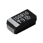
B, C, D, E Case
Marking
Capacitor marking includes an anode (+) polarity band, capacitance in microfarads and the voltage rating. “A” case capacitors use a letter
code for the voltage and EIA capacitance code.
The Vishay identification marking is included if space permits. Vishay marking (“circled 2”) may show additives in the form of short lines,
depicting actual manufacturing facility. For A case capacitors discontinuation in polarity bar maybe used as actual manufacturing facility
designation. Capacitors rated at 6.3 V are marked 6 V. Uppercase letter “H” indicates lead (Pb)-free capacitors; lowercase letter “h”
indicates SnPb containing capacitors.
A manufacturing date code is marked on all capacitors. for details see FAQ: www.vishay.com/doc?40110.
Call the factory for further explanation.
STANDARD RATINGS
CAPACITANCE
(μF)
CASE CODE
10
10
15
22
22
33
33
47
47
68
100
A
A
B
B
B
B
B
B
C
B
E
2.2
4.7
4.7
6.8
10
10
10
10
10
15
15
15
15
15
15
15
A
A
B
A
A
A
B
C
C
A
A
B
B
B
C
C
PART NUMBER
MAX. DCL
AT +25 °C
(μA)
MAX. DF
AT +25 °C
(%)
6.3 VDC AT +85 °C; 4 VDC AT +125 °C; 3.15 VDC AT +150 °C
TH3A106(1)6R3(3)3400
0.6
6
TH3A106(1)6R3(3)2700
0.6
6
TH3B156(1)6R3(2)1800
0.9
6
TH3B226(1)6R3(2)2000
1.3
6
TH3B226(1)6R3(2)1500
1.3
6
TH3B336(1)6R3(2)1900
2.0
6
TH3B336(1)6R3(2)1700
2.0
6
TH3B476(1)6R3(2)1800
2.8
8
TH3C476(1)6R3(3)0800
2.8
6
TH3B686(1)6R3(2)1800
4.1
6
TH3E107(1)6R3(3)0300
6.0
6
10 VDC AT +85 °C; 7 VDC AT +125 °C; 5 VDC AT +150 °C
TH3A225(1)010(3)4600
0.5
6
TH3A475(1)010(3)2900
0.5
6
TH3B475(1)010(2)2700
0.5
6
TH3A685(1)010(3)2600
6.8
6
TH3A106(1)010(3)3400
1.0
6
TH3A106(1)010(3)2000
1.0
6
TH3B106(1)010(2)1800
1.0
6
TH3C106(1)010(3)1800
1.0
6
TH3C106(1)010(3)1700
1.0
6
TH3A156(1)010(3)2900
1.0
6
TH3A156(1)010(3)2000
1.0
6
TH3B156(1)010(2)2000
1.0
6
TH3B156(1)010(2)1800
1.0
6
TH3B156(1)010(2)1500
1.0
6
TH3C156(1)010(3)1800
1.0
6
TH3C156(1)010(3)1400
1.0
6
MAX. ESR
AT +25 °C
100 kHz
(Ω)
MAX. RIPPLE
100 kHz
IRMS
(A)
3.40
2.70
1.80
2.00
1.50
1.90
1.70
1.80
0.80
1.80
0.30
0.15
0.17
0.22
0.21
0.24
0.21
0.22
0.22
0.37
0.22
0.74
4.60
2.90
2.70
2.60
3.40
2.00
1.80
1.80
1.70
2.90
2.00
2.00
1.80
1.50
1.80
1.40
0.13
0.16
0.18
0.17
0.15
0.19
0.22
0.25
0.25
0.16
0.19
0.21
0.22
0.24
0.25
0.28
Note
• Part number definitions:
(1) Capacitance tolerance: K, M
(2) Termination and packaging: C, D, E, F, V, U, T, W
(3) Termination and packaging: A, B, C, D, E, F, V, U, T, W
Revision: 17-Oct-2022
Document Number: 40084
3
For technical questions, contact: tantalum@vishay.com
THIS DOCUMENT IS SUBJECT TO CHANGE WITHOUT NOTICE. THE PRODUCTS DESCRIBED HEREIN AND THIS DOCUMENT
ARE SUBJECT TO SPECIFIC DISCLAIMERS, SET FORTH AT www.vishay.com/doc?91000
�TH3
www.vishay.com
Vishay Sprague
STANDARD RATINGS
CAPACITANCE
(μF)
CASE CODE
22
22
22
33
33
33
47
47
47
47
68
68
68
68
68
100
100
100
150
220
B
C
C
B
B
D
B
C
C
D
C
C
D
D
D
C
C
D
D
E
1.0
2.2
3.3
3.3
4.7
4.7
6.8
6.8
6.8
6.8
10
10
10
15
15
22
22
22
22
33
33
33
47
47
47
68
100
100
100
A
A
A
B
A
B
A
A
B
C
B
C
C
B
C
B
C
C
D
C
C
D
C
C
D
D
D
E
E
PART NUMBER
MAX. DCL
AT +25 °C
(μA)
MAX. DF
AT +25 °C
(%)
10 VDC AT +85 °C; 7 VDC AT +125 °C; 5 VDC AT +150 °C
TH3B226(1)010(2)1500
2.2
6
TH3C226(1)010(3)1500
2.2
6
TH3C226(1)010(3)1100
2.2
6
TH3B336(1)010(2)1900
3.3
6
TH3B336(1)010(2)1400
3.3
6
TH3D336(1)010(3)0800
3.3
6
TH3B476(1)010(2)1800
4.7
6
TH3C476(1)010(3)0800
4.7
6
TH3C476(1)010(3)0500
4.7
6
TH3D476(1)010(3)0600
4.7
6
TH3C686(1)010(3)1000
6.8
8
TH3C686(1)010(3)0800
6.8
8
TH3D686(1)010(3)1000
6.8
6
TH3D686(1)010(3)0600
6.8
6
TH3D686(1)010(3)0400
6.8
6
TH3C107(1)010(3)0900
10.0
6
TH3C107(1)010(3)0500
10.0
6
TH3D107(1)010(3)0600
10.0
8
TH3D157(1)010(3)0600
15.0
8
TH3E227(1)010(3)0500
22.0
8
16 VDC AT +85 °C; 10 VDC AT +125 °C; 8 VDC AT +150 °C
TH3A105(1)016(3)6500
0.5
4
TH3A225(1)016(3)4300
0.5
6
TH3A335(1)016(3)3400
0.5
6
TH3B335(1)016(2)3000
0.5
6
TH3A475(1)016(3)2900
0.8
6
TH3B475(1)016(2)2100
0.8
6
TH3A685(1)016(3)2600
1.1
6
TH3A685(1)016(3)2000
1.1
6
TH3B685(1)016(2)1800
1.1
6
TH3C685(1)016(3)1700
1.1
6
TH3B106(1)016(2)2000
1.6
6
TH3C106(1)016(3)1400
1.6
6
TH3C106(1)016(3)0800
1.6
6
TH3B156(1)016(2)2000
2.4
6
TH3C156(1)016(3)1000
2.4
6
TH3B226(1)016(2)1900
3.5
6
TH3C226(1)016(3)1000
3.5
6
TH3C226(1)016(3)0800
3.5
4.5
TH3D226(1)016(3)0800
3.5
6
TH3C336(1)016(3)0900
5.3
6
TH3C336(1)016(3)0600
5.3
6
TH3D336(1)016(3)0600
5.3
6
TH3C476(1)016(3)0800
7.5
6
TH3C476(1)016(3)0600
7.5
6
TH3D476(1)016(3)0600
7.5
6
TH3D686(1)016(3)0600
10.9
6
TH3D107(1)016(3)0600
16.0
8
TH3E107(1)016(3)0600
16.0
8
TH3E107(1)016(3)0150
16.0
8
MAX. ESR
AT +25 °C
100 kHz
(Ω)
MAX. RIPPLE
100 kHz
IRMS
(A)
1.50
1.50
1.10
1.90
1.40
0.80
1.80
0.80
0.50
0.60
1.00
0.80
1.00
0.60
0.40
0.90
0.50
0.60
0.60
0.50
0.24
0.27
0.32
0.21
0.25
0.43
0.22
0.37
0.47
0.50
0.33
0.37
0.39
0.50
0.61
0.35
0.47
0.50
0.50
0.61
6.50
4.30
3.40
3.00
2.90
2.10
2.60
2.00
1.80
1.70
2.00
1.40
0.80
2.00
1.00
1.90
1.00
0.80
0.80
0.90
0.60
0.60
0.80
0.60
0.60
0.60
0.60
0.60
0.15
0.11
0.13
0.15
0.17
0.16
0.2
0.17
0.19
0.22
0.25
0.21
0.28
0.37
0.21
0.33
0.21
0.33
0.37
0.43
0.35
0.43
0.50
0.37
0.43
0.43
0.50
0.50
0.56
1.11
Note
• Part number definitions:
(1) Capacitance tolerance: K, M
(2) Termination and packaging: C, D, E, F, V, U, T, W
(3) Termination and packaging: A, B, C, D, E, F, V, U, T, W
Revision: 17-Oct-2022
Document Number: 40084
4
For technical questions, contact: tantalum@vishay.com
THIS DOCUMENT IS SUBJECT TO CHANGE WITHOUT NOTICE. THE PRODUCTS DESCRIBED HEREIN AND THIS DOCUMENT
ARE SUBJECT TO SPECIFIC DISCLAIMERS, SET FORTH AT www.vishay.com/doc?91000
�TH3
www.vishay.com
Vishay Sprague
STANDARD RATINGS
MAX. ESR
AT +25 °C
100 kHz
(Ω)
MAX. RIPPLE
100 kHz
IRMS
(A)
4
5.90
0.11
6
5.90
0.11
0.5
6
3.50
0.16
0.7
6
2.70
0.18
MAX. DCL
AT +25 °C
(μA)
MAX. DF
AT +25 °C
(%)
CAPACITANCE
(μF)
CASE CODE
1.0
A
TH3A105(1)020(3)5900
0.5
2.2
A
TH3A225(1)020(3)5900
0.5
2.2
B
TH3B225(1)020(2)3500
3.3
B
TH3B335(1)020(2)2700
3.3
C
TH3C335(1)020(3)2700
0.7
6
2.70
0.20
4.7
A
TH3A475(1)020(3)5000
0.9
6
5.00
0.12
4.7
B
TH3B475(1)020(2)2900
0.9
6
2.90
0.17
4.7
B
TH3B475(1)020(2)1900
0.9
6
1.90
0.21
4.7
C
TH3C475(1)020(3)1700
0.9
6
1.70
0.25
10
C
TH3C106(1)020(3)1100
2.0
6
1.10
0.32
15
B
TH3B156(1)020(2)2000
3.0
6
2.00
0.21
15
C
TH3C156(1)020(3)1000
3.0
6
1.00
0.33
0.41
PART NUMBER
20 VDC AT +85 °C; 13 VDC AT +125 °C; 10 VDC AT +150 °C
15
D
TH3D156(1)020(3)0900
3.0
6
0.90
22
C
TH3C226(1)020(3)1000
4.4
6
1.00
0.33
22
D
TH3D226(1)020(3)0700
4.4
6
0.70
0.46
33
D
TH3D336(1)020(3)0600
6.6
6
0.60
0.5
47
D
TH3D476(1)020(3)0700
9.4
6
0.70
0.46
47
E
TH3E476(1)020(3)0600
9.4
8
0.60
0.56
68
E
TH3E686(1)020(3)0600
13.6
8
0.60
0.56
25 VDC AT +85 °C; 17 VDC AT +125 °C; 12.5 VDC AT +150 °C
0.47
A
TH3A474(1)025(3)14R0
0.5
4
14.00
0.073
1.0
A
TH3A105(1)025(3)5200
0.5
4
5.20
0.12
1.0
A
TH3A105(1)025(3)3000
0.5
4
3.00
0.16
1.0
B
TH3B105(1)025(2)5000
0.5
4
5.00
0.13
2.2
A
TH3A225(1)025(3)5200
0.6
6
5.20
0.12
2.2
B
TH3B225(1)025(2)3000
0.6
6
3.00
0.17
3.3
B
TH3B335(1)025(2)3000
0.8
6
3.00
0.17
3.3
C
TH3C335(1)025(3)2000
0.8
6
2.00
0.23
0.12
4.7
A
TH3A475(1)025(3)5000
1.2
6
5.00
4.7
B
TH3B475(1)025(2)2800
1.2
6
2.80
0.17
4.7
C
TH3C475(1)025(3)1600
1.2
6
1.60
0.26
6.8
B
TH3B685(1)025(2)2400
1.7
6
2.40
0.19
6.8
C
TH3C685(1)025(3)1400
1.7
6
1.40
0.28
10
C
TH3C106(1)025(3)1100
2.5
6
1.10
0.32
10
D
TH3D106(1)025(3)0900
2.5
6
0.90
0.41
15
B
TH3B156(1)025(2)2000
3.8
6
2.00
0.21
15
B
TH3B156(1)025(2)1400
3.8
6
1.40
0.25
15
C
TH3C156(1)025(3)1200
3.8
6
1.20
0.30
15
D
TH3D156(1)025(3)0700
3.8
6
0.70
0.46
22
D
TH3D226(1)025(3)0600
5.5
6
0.60
0.50
33
D
TH3D336(1)025(3)0500
8.3
6
0.50
0.55
47
E
TH3E476(1)025(3)0600
11.8
6
0.60
0.56
Note
• Part number definitions:
(1) Capacitance tolerance: K, M
(2) Termination and packaging: C, D, E, F, V, U, T, W
(3) Termination and packaging: A, B, C, D, E, F, V, U, T, W
Revision: 17-Oct-2022
Document Number: 40084
5
For technical questions, contact: tantalum@vishay.com
THIS DOCUMENT IS SUBJECT TO CHANGE WITHOUT NOTICE. THE PRODUCTS DESCRIBED HEREIN AND THIS DOCUMENT
ARE SUBJECT TO SPECIFIC DISCLAIMERS, SET FORTH AT www.vishay.com/doc?91000
�TH3
www.vishay.com
Vishay Sprague
35 VDC AT +85 °C; 23 VDC AT +125 °C; 17.5 VDC AT +150 °C
0.33
A
TH3A334(1)035(3)11R0
0.5
4
11.00
0.08
1.0
A
TH3A105(1)035(3)6600
0.5
4
6.60
0.11
Revision: 17-Oct-2022
Document Number: 40084
6
For technical questions, contact: tantalum@vishay.com
THIS DOCUMENT IS SUBJECT TO CHANGE WITHOUT NOTICE. THE PRODUCTS DESCRIBED HEREIN AND THIS DOCUMENT
ARE SUBJECT TO SPECIFIC DISCLAIMERS, SET FORTH AT www.vishay.com/doc?91000
�


 工商网监
湘ICP备2023018690号
工商网监
湘ICP备2023018690号
