TH3
www.vishay.com
Vishay Sprague
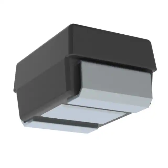
Solid Tantalum Surface Mount Capacitors
TANTAMOUNT™ Molded Case, HI-TMP®
High Temperature 150 °C, Automotive Grade
FEATURES
• Operating temperature up to 150 °C with 50 %
voltage derating
• AEC-Q200 qualified
• 100 % surge current tested
Available
(B, C, D, E case sizes)
Available
• RoHS-compliant terminations available:
matte tin (all cases), gold (A, C, D, and E cases)
• Standard EIA 535BAAC case size (A through E)
• Compliant terminations
Available
• Moisture sensitivity level 1
• Material categorization: for definitions of compliance
please see www.vishay.com/doc?99912
LINKS TO ADDITIONAL RESOURCES
3D 3D
3D Models
Calculators
Related
Documents
Infographics
Did You
Know?
Technical
Notes
Note
* This datasheet provides information about parts that are
RoHS-compliant and / or parts that are non RoHS-compliant. For
example, parts with lead (Pb) terminations are not RoHS-compliant.
Please see the information / tables in this datasheet for details
APPLICATIONS
PERFORMANCE / ELECTRICAL
CHARACTERISTICS
• Automotive
• Industrial
• High temperature sensors
www.vishay.com/doc?40215
Operating Temperature: -55 °C to +150 °C
Capacitance Range: 0.33 μF to 220 μF
Capacitance Tolerance: ± 10 %, ± 20 %
Voltage Rating: 6.3 VDC to 50 VDC
Note
• For recommended voltage derating guidelines see “Typical
Performance Characteristics”
ORDERING INFORMATION
TH3
D
106
K
035
C
0700
TYPE
CASE
CODE
CAPACITANCE
CAPACITANCE
TOLERANCE
DC VOLTAGE
RATING AT +85 °C
TERMINATION AND
PACKAGING
ESR
See
Ratings
and Case
Codes
table.
This is expressed in
picofarads. The first
two digits are the
significant figures.
The third is the
number of zeros
to follow.
K = ± 10 %
M = ± 20 %
This is expressed in V.
To complete the
three-digit block, zeros
precede the voltage
rating. A decimal point
is indicated by an “R”.
(6R3 = 6.3 V)
Gold
A = 7" (178 mm) reel
B = 13" (330 mm) reel
Maximum
100 kHz ESR
0500 = 500 mΩ
5000 = 5.0 Ω
10R0 = 10.0 Ω
Matte tin
C = 7" (178 mm) reel
D = 13" (330 mm) reel
V = 7" (178 mm) reel,
dry pack
U = 13" (330 mm) reel,
dry pack
Tin / lead
E = 7" (178 mm) reel
F = 13" (330 mm) reel
T = 7" (178 mm) reel,
dry pack
W = 13" (330 mm) reel,
dry pack
Notes
• We reserve the right to supply higher voltage ratings and tighter capacitance tolerance capacitors in the same case size. Voltage
substitutions will be marked with the higher voltage rating
• Dry pack as specified in J-STD-033
Revision: 17-Oct-2022
Document Number: 40084
1
For technical questions, contact: tantalum@vishay.com
THIS DOCUMENT IS SUBJECT TO CHANGE WITHOUT NOTICE. THE PRODUCTS DESCRIBED HEREIN AND THIS DOCUMENT
ARE SUBJECT TO SPECIFIC DISCLAIMERS, SET FORTH AT www.vishay.com/doc?91000
�TH3
www.vishay.com
Vishay Sprague
DIMENSIONS in inches [millimeters]
L
W
H
TW
Glue Pad
TH (MIN.)
P
Glue Pad
CASE CODE
EIA SIZE
L
W
H
P
TW
TH (MIN.)
A
3216-18
B
3528-21
C
6032-28
D
7343-31
E
7343-43
0.126 ± 0.008
[3.2 ± 0.20]
0.138 ± 0.008
[3.5 ± 0.20]
0.236 ± 0.012
[6.0 ± 0.30]
0.287 ± 0.012
[7.3 ± 0.30]
0.287 ± 0.012
[7.3 ± 0.30]
0.063 ± 0.008
[1.6 ± 0.20]
0.110 ± 0.008
[2.8 ± 0.20]
0.126 ± 0.012
[3.2 ± 0.30]
0.169 ± 0.012
[4.3 ± 0.30]
0.169 ± 0.012
[4.3 ± 0.30]
0.063 ± 0.008
[1.6 ± 0.20]
0.075 ± 0.008
[1.9 ± 0.20]
0.098 ± 0.012
[2.5 ± 0.30]
0.110 ± 0.012
[2.8 ± 0.30]
0.157 ± 0.012
[4.0 ± 0.30]
0.031 ± 0.012
[0.80 ± 0.30]
0.031 ± 0.012
[0.80 ± 0.30]
0.051 ± 0.012
[1.3 ± 0.30]
0.051 ± 0.012
[1.3 ± 0.30]
0.051 ± 0.012
[1.3 ± 0.30]
0.047 ± 0.004
[1.2 ± 0.10]
0.087 ± 0.004
[2.2 ± 0.10]
0.087 ± 0.004
[2.2 ± 0.10]
0.094 ± 0.004
[2.4 ± 0.10]
0.094 ± 0.004
[2.4 ± 0.10]
0.028
[0.70]
0.028
[0.70]
0.039
[1.0]
0.039
[1.0]
0.039
[1.0]
35 V
A (11.0)
50 V
C (3.3)
Note
• Glue pad (non-conductive, part of molded case) is dedicated for glue attachment (as user option)
RATINGS AND CASE CODES
μF
0.33
0.47
0.68
6.3 V
10 V
16 V
20 V
25 V
A (14.0)
1.0
1.5
2.2
A (4.6)
3.3
A (6.5)
A (5.9)
A (3.0, 5.2) /
B (5.0)
A (6.6) / B (4.4)
A (4.3)
A (5.9) / B (3.5)
A (5.2) / B (3.0)
A (3.4) / B (3.0)
B (2.7) / C (3.7)
B (3.0) / C (2.0)
B (4.2) / C (3.3)
B (2.5) / C (2.2)
B (2.5, 3.5) /
C (1.7)
A (5.0) /
B (2.9, 1.9) /
C (1.7)
4.7
A (2.9) / B (2.7)
A (2.9) / B (2.1)
6.8
A (2.6)
A (2.6, 2.0) /
B (1.8) / C (1.7)
A (3.4, 2.0) /
B (1.8) /
C (1.8, 1.7)
A (2.9, 2.0) /
B (2.0, 1.8, 1.5) /
C (1.8, 1.4)
B (2.0) /
C (1.4, 0.8)
10
A (3.4, 2.7)
15
B (1.8)
22
B (2.0, 1.5)
33
B (1.9, 1.7)
47
B (1.8) / C (0.8)
68
B (1.8)
100
E (0.3)
150
220
B (1.5) /
C (1.5, 1.1)
B (1.9, 1.4) /
D (0.8)
B (1.8) /
C (0.8, 0.5) /
D (0.6)
C (1.0, 0.8) /
D (1.0, 0.6, 0.4)
C (0.9, 0.5) /
D (0.6)
D (0.6)
E (0.5)
D (1.7)
A (5.0) / B (2.8) / B (3.1) / C (1.3) /
C (1.5) / D (0.9)
C (1.6)
D (1.0)
B (2.4) / C (1.4)
C (1.8) / D (0.9)
D (0.9)
C (1.1) / D (0.9)
C (1.6) /
D (0.25, 0.3, 0.7)
D (0.8) / E (0.5)
B (1.4, 2.0) /
C (1.2) / D (0.7)
D (0.7)
C (1.0) / D (0.7)
D (0.6)
D (0.3, 0.6) /
E (0.5)
D (0.6)
D (0.5)
C (0.8, 0.6) /
D (0.6)
D (0.7) / E (0.6)
E (0.6)
D (0.6)
E (0.6)
C (1.1)
B (2.0) / C (1.0) B (2.0) / C (1.0) /
D (0.9)
B (1.9) /
C (0.8, 1.0) /
D (0.8)
C (0.9, 0.6) /
D (0.6)
D (0.6) /
E (0.6, 0.15)
Note
• ESR limits in Ω are shown in parenthesis
Revision: 17-Oct-2022
Document Number: 40084
2
For technical questions, contact: tantalum@vishay.com
THIS DOCUMENT IS SUBJECT TO CHANGE WITHOUT NOTICE. THE PRODUCTS DESCRIBED HEREIN AND THIS DOCUMENT
ARE SUBJECT TO SPECIFIC DISCLAIMERS, SET FORTH AT www.vishay.com/doc?91000
�TH3
www.vishay.com
Vishay Sprague
MARKING
“A” CASE VOLTAGE CODE
Capacitance code, pF
Indicates
high temperature
Date code
designation
V 104H
Voltage
code
Polarity band (+)
A Case
VOLTS
CODE
4.0
G
6.3
J
10
A
16
C
20
D
25
E
35
V
50
T
Indicates high temperature
Voltage
Capacitance, μF
22
Polarity
band (+)
XX
Date code
H10
2
Vishay marking
B, C, D, E Case
Marking
Capacitor marking includes an anode (+) polarity band, capacitance in microfarads and the voltage rating. “A” case capacitors use a letter
code for the voltage and EIA capacitance code.
The Vishay identification marking is included if space permits. Vishay marking (“circled 2”) may show additives in the form of short lines,
depicting actual manufacturing facility. For A case capacitors discontinuation in polarity bar maybe used as actual manufacturing facility
designation. Capacitors rated at 6.3 V are marked 6 V. Uppercase letter “H” indicates lead (Pb)-free capacitors; lowercase letter “h”
indicates SnPb containing capacitors.
A manufacturing date code is marked on all capacitors. for details see FAQ: www.vishay.com/doc?40110.
Call the factory for further explanation.
STANDARD RATINGS
CAPACITANCE
(μF)
CASE CODE
10
10
15
22
22
33
33
47
47
68
100
A
A
B
B
B
B
B
B
C
B
E
2.2
4.7
4.7
6.8
10
10
10
10
10
15
15
15
15
15
15
15
A
A
B
A
A
A
B
C
C
A
A
B
B
B
C
C
PART NUMBER
MAX. DCL
AT +25 °C
(μA)
MAX. DF
AT +25 °C
(%)
6.3 VDC AT +85 °C; 4 VDC AT +125 °C; 3.15 VDC AT +150 °C
TH3A106(1)6R3(3)3400
0.6
6
TH3A106(1)6R3(3)2700
0.6
6
TH3B156(1)6R3(2)1800
0.9
6
TH3B226(1)6R3(2)2000
1.3
6
TH3B226(1)6R3(2)1500
1.3
6
TH3B336(1)6R3(2)1900
2.0
6
TH3B336(1)6R3(2)1700
2.0
6
TH3B476(1)6R3(2)1800
2.8
8
TH3C476(1)6R3(3)0800
2.8
6
TH3B686(1)6R3(2)1800
4.1
6
TH3E107(1)6R3(3)0300
6.0
6
10 VDC AT +85 °C; 7 VDC AT +125 °C; 5 VDC AT +150 °C
TH3A225(1)010(3)4600
0.5
6
TH3A475(1)010(3)2900
0.5
6
TH3B475(1)010(2)2700
0.5
6
TH3A685(1)010(3)2600
6.8
6
TH3A106(1)010(3)3400
1.0
6
TH3A106(1)010(3)2000
1.0
6
TH3B106(1)010(2)1800
1.0
6
TH3C106(1)010(3)1800
1.0
6
TH3C106(1)010(3)1700
1.0
6
TH3A156(1)010(3)2900
1.0
6
TH3A156(1)010(3)2000
1.0
6
TH3B156(1)010(2)2000
1.0
6
TH3B156(1)010(2)1800
1.0
6
TH3B156(1)010(2)1500
1.0
6
TH3C156(1)010(3)1800
1.0
6
TH3C156(1)010(3)1400
1.0
6
MAX. ESR
AT +25 °C
100 kHz
(Ω)
MAX. RIPPLE
100 kHz
IRMS
(A)
3.40
2.70
1.80
2.00
1.50
1.90
1.70
1.80
0.80
1.80
0.30
0.15
0.17
0.22
0.21
0.24
0.21
0.22
0.22
0.37
0.22
0.74
4.60
2.90
2.70
2.60
3.40
2.00
1.80
1.80
1.70
2.90
2.00
2.00
1.80
1.50
1.80
1.40
0.13
0.16
0.18
0.17
0.15
0.19
0.22
0.25
0.25
0.16
0.19
0.21
0.22
0.24
0.25
0.28
Note
• Part number definitions:
(1) Capacitance tolerance: K, M
(2) Termination and packaging: C, D, E, F, V, U, T, W
(3) Termination and packaging: A, B, C, D, E, F, V, U, T, W
Revision: 17-Oct-2022
Document Number: 40084
3
For technical questions, contact: tantalum@vishay.com
THIS DOCUMENT IS SUBJECT TO CHANGE WITHOUT NOTICE. THE PRODUCTS DESCRIBED HEREIN AND THIS DOCUMENT
ARE SUBJECT TO SPECIFIC DISCLAIMERS, SET FORTH AT www.vishay.com/doc?91000
�TH3
www.vishay.com
Vishay Sprague
STANDARD RATINGS
CAPACITANCE
(μF)
CASE CODE
22
22
22
33
33
33
47
47
47
47
68
68
68
68
68
100
100
100
150
220
B
C
C
B
B
D
B
C
C
D
C
C
D
D
D
C
C
D
D
E
1.0
2.2
3.3
3.3
4.7
4.7
6.8
6.8
6.8
6.8
10
10
10
15
15
22
22
22
22
33
33
33
47
47
47
68
100
100
100
A
A
A
B
A
B
A
A
B
C
B
C
C
B
C
B
C
C
D
C
C
D
C
C
D
D
D
E
E
PART NUMBER
MAX. DCL
AT +25 °C
(μA)
MAX. DF
AT +25 °C
(%)
10 VDC AT +85 °C; 7 VDC AT +125 °C; 5 VDC AT +150 °C
TH3B226(1)010(2)1500
2.2
6
TH3C226(1)010(3)1500
2.2
6
TH3C226(1)010(3)1100
2.2
6
TH3B336(1)010(2)1900
3.3
6
TH3B336(1)010(2)1400
3.3
6
TH3D336(1)010(3)0800
3.3
6
TH3B476(1)010(2)1800
4.7
6
TH3C476(1)010(3)0800
4.7
6
TH3C476(1)010(3)0500
4.7
6
TH3D476(1)010(3)0600
4.7
6
TH3C686(1)010(3)1000
6.8
8
TH3C686(1)010(3)0800
6.8
8
TH3D686(1)010(3)1000
6.8
6
TH3D686(1)010(3)0600
6.8
6
TH3D686(1)010(3)0400
6.8
6
TH3C107(1)010(3)0900
10.0
6
TH3C107(1)010(3)0500
10.0
6
TH3D107(1)010(3)0600
10.0
8
TH3D157(1)010(3)0600
15.0
8
TH3E227(1)010(3)0500
22.0
8
16 VDC AT +85 °C; 10 VDC AT +125 °C; 8 VDC AT +150 °C
TH3A105(1)016(3)6500
0.5
4
TH3A225(1)016(3)4300
0.5
6
TH3A335(1)016(3)3400
0.5
6
TH3B335(1)016(2)3000
0.5
6
TH3A475(1)016(3)2900
0.8
6
TH3B475(1)016(2)2100
0.8
6
TH3A685(1)016(3)2600
1.1
6
TH3A685(1)016(3)2000
1.1
6
TH3B685(1)016(2)1800
1.1
6
TH3C685(1)016(3)1700
1.1
6
TH3B106(1)016(2)2000
1.6
6
TH3C106(1)016(3)1400
1.6
6
TH3C106(1)016(3)0800
1.6
6
TH3B156(1)016(2)2000
2.4
6
TH3C156(1)016(3)1000
2.4
6
TH3B226(1)016(2)1900
3.5
6
TH3C226(1)016(3)1000
3.5
6
TH3C226(1)016(3)0800
3.5
4.5
TH3D226(1)016(3)0800
3.5
6
TH3C336(1)016(3)0900
5.3
6
TH3C336(1)016(3)0600
5.3
6
TH3D336(1)016(3)0600
5.3
6
TH3C476(1)016(3)0800
7.5
6
TH3C476(1)016(3)0600
7.5
6
TH3D476(1)016(3)0600
7.5
6
TH3D686(1)016(3)0600
10.9
6
TH3D107(1)016(3)0600
16.0
8
TH3E107(1)016(3)0600
16.0
8
TH3E107(1)016(3)0150
16.0
8
MAX. ESR
AT +25 °C
100 kHz
(Ω)
MAX. RIPPLE
100 kHz
IRMS
(A)
1.50
1.50
1.10
1.90
1.40
0.80
1.80
0.80
0.50
0.60
1.00
0.80
1.00
0.60
0.40
0.90
0.50
0.60
0.60
0.50
0.24
0.27
0.32
0.21
0.25
0.43
0.22
0.37
0.47
0.50
0.33
0.37
0.39
0.50
0.61
0.35
0.47
0.50
0.50
0.61
6.50
4.30
3.40
3.00
2.90
2.10
2.60
2.00
1.80
1.70
2.00
1.40
0.80
2.00
1.00
1.90
1.00
0.80
0.80
0.90
0.60
0.60
0.80
0.60
0.60
0.60
0.60
0.60
0.15
0.11
0.13
0.15
0.17
0.16
0.2
0.17
0.19
0.22
0.25
0.21
0.28
0.37
0.21
0.33
0.21
0.33
0.37
0.43
0.35
0.43
0.50
0.37
0.43
0.43
0.50
0.50
0.56
1.11
Note
• Part number definitions:
(1) Capacitance tolerance: K, M
(2) Termination and packaging: C, D, E, F, V, U, T, W
(3) Termination and packaging: A, B, C, D, E, F, V, U, T, W
Revision: 17-Oct-2022
Document Number: 40084
4
For technical questions, contact: tantalum@vishay.com
THIS DOCUMENT IS SUBJECT TO CHANGE WITHOUT NOTICE. THE PRODUCTS DESCRIBED HEREIN AND THIS DOCUMENT
ARE SUBJECT TO SPECIFIC DISCLAIMERS, SET FORTH AT www.vishay.com/doc?91000
�TH3
www.vishay.com
Vishay Sprague
STANDARD RATINGS
MAX. ESR
AT +25 °C
100 kHz
(Ω)
MAX. RIPPLE
100 kHz
IRMS
(A)
4
5.90
0.11
6
5.90
0.11
0.5
6
3.50
0.16
0.7
6
2.70
0.18
MAX. DCL
AT +25 °C
(μA)
MAX. DF
AT +25 °C
(%)
CAPACITANCE
(μF)
CASE CODE
1.0
A
TH3A105(1)020(3)5900
0.5
2.2
A
TH3A225(1)020(3)5900
0.5
2.2
B
TH3B225(1)020(2)3500
3.3
B
TH3B335(1)020(2)2700
3.3
C
TH3C335(1)020(3)2700
0.7
6
2.70
0.20
4.7
A
TH3A475(1)020(3)5000
0.9
6
5.00
0.12
4.7
B
TH3B475(1)020(2)2900
0.9
6
2.90
0.17
4.7
B
TH3B475(1)020(2)1900
0.9
6
1.90
0.21
4.7
C
TH3C475(1)020(3)1700
0.9
6
1.70
0.25
10
C
TH3C106(1)020(3)1100
2.0
6
1.10
0.32
15
B
TH3B156(1)020(2)2000
3.0
6
2.00
0.21
15
C
TH3C156(1)020(3)1000
3.0
6
1.00
0.33
0.41
PART NUMBER
20 VDC AT +85 °C; 13 VDC AT +125 °C; 10 VDC AT +150 °C
15
D
TH3D156(1)020(3)0900
3.0
6
0.90
22
C
TH3C226(1)020(3)1000
4.4
6
1.00
0.33
22
D
TH3D226(1)020(3)0700
4.4
6
0.70
0.46
33
D
TH3D336(1)020(3)0600
6.6
6
0.60
0.5
47
D
TH3D476(1)020(3)0700
9.4
6
0.70
0.46
47
E
TH3E476(1)020(3)0600
9.4
8
0.60
0.56
68
E
TH3E686(1)020(3)0600
13.6
8
0.60
0.56
25 VDC AT +85 °C; 17 VDC AT +125 °C; 12.5 VDC AT +150 °C
0.47
A
TH3A474(1)025(3)14R0
0.5
4
14.00
0.073
1.0
A
TH3A105(1)025(3)5200
0.5
4
5.20
0.12
1.0
A
TH3A105(1)025(3)3000
0.5
4
3.00
0.16
1.0
B
TH3B105(1)025(2)5000
0.5
4
5.00
0.13
2.2
A
TH3A225(1)025(3)5200
0.6
6
5.20
0.12
2.2
B
TH3B225(1)025(2)3000
0.6
6
3.00
0.17
3.3
B
TH3B335(1)025(2)3000
0.8
6
3.00
0.17
3.3
C
TH3C335(1)025(3)2000
0.8
6
2.00
0.23
0.12
4.7
A
TH3A475(1)025(3)5000
1.2
6
5.00
4.7
B
TH3B475(1)025(2)2800
1.2
6
2.80
0.17
4.7
C
TH3C475(1)025(3)1600
1.2
6
1.60
0.26
6.8
B
TH3B685(1)025(2)2400
1.7
6
2.40
0.19
6.8
C
TH3C685(1)025(3)1400
1.7
6
1.40
0.28
10
C
TH3C106(1)025(3)1100
2.5
6
1.10
0.32
10
D
TH3D106(1)025(3)0900
2.5
6
0.90
0.41
15
B
TH3B156(1)025(2)2000
3.8
6
2.00
0.21
15
B
TH3B156(1)025(2)1400
3.8
6
1.40
0.25
15
C
TH3C156(1)025(3)1200
3.8
6
1.20
0.30
15
D
TH3D156(1)025(3)0700
3.8
6
0.70
0.46
22
D
TH3D226(1)025(3)0600
5.5
6
0.60
0.50
33
D
TH3D336(1)025(3)0500
8.3
6
0.50
0.55
47
E
TH3E476(1)025(3)0600
11.8
6
0.60
0.56
Note
• Part number definitions:
(1) Capacitance tolerance: K, M
(2) Termination and packaging: C, D, E, F, V, U, T, W
(3) Termination and packaging: A, B, C, D, E, F, V, U, T, W
Revision: 17-Oct-2022
Document Number: 40084
5
For technical questions, contact: tantalum@vishay.com
THIS DOCUMENT IS SUBJECT TO CHANGE WITHOUT NOTICE. THE PRODUCTS DESCRIBED HEREIN AND THIS DOCUMENT
ARE SUBJECT TO SPECIFIC DISCLAIMERS, SET FORTH AT www.vishay.com/doc?91000
�TH3
www.vishay.com
Vishay Sprague
STANDARD RATINGS
MAX. DCL
AT +25 °C
(μA)
MAX. DF
AT +25 °C
(%)
MAX. ESR
AT +25 °C
100 kHz
(Ω)
MAX. RIPPLE
100 kHz
IRMS
(A)
CAPACITANCE
(μF)
CASE CODE
0.33
A
TH3A334(1)035(3)11R0
0.5
4
11.00
0.08
1.0
A
TH3A105(1)035(3)6600
0.5
4
6.60
0.11
1.0
B
TH3B105(1)035(2)4400
0.5
4
4.40
0.14
1.5
B
TH3B155(1)035(2)4200
0.5
6
4.20
0.14
1.5
C
TH3C155(1)035(3)3300
0.5
6
3.30
0.18
2.2
B
TH3B225(1)035(2)2500
0.8
6
2.50
0.18
2.2
C
TH3C225(1)035(3)2200
0.8
6
2.20
0.22
3.3
B
TH3B335(1)035(2)3500
1.2
6
3.50
0.16
3.3
B
TH3B335(1)035(2)2500
1.2
6
2.50
0.18
3.3
C
TH3C335(1)035(3)1700
1.2
6
1.70
0.25
PART NUMBER
35 VDC AT +85 °C; 23 VDC AT +125 °C; 17.5 VDC AT +150 °C
4.7
B
TH3B475(1)035(2)3100
1.7
6
3.10
0.17
4.7
C
TH3C475(1)035(3)1300
1.6
6
1.30
0.29
0.39
4.7
D
TH3D475(1)035(3)1000
1.6
6
1.00
6.8
C
TH3C685(1)035(3)1800
2.4
6
1.80
0.25
6.8
D
TH3D685(1)035(3)0900
2.4
6
0.90
0.41
10
C
TH3C106(1)035(3)1600
3.5
6
1.60
0.26
10
D
TH3D106(1)035(3)0700
3.5
6
0.70
0.46
10
D
TH3D106(1)035(3)0300
3.5
6
0.30
0.71
10
D
TH3D106(1)035(3)0250
3.5
6
0.25
0.77
15
D
TH3D156(1)035(3)0700
5.3
6
0.70
0.46
22
D
TH3D226(1)035(3)0600
7.7
6
0.60
0.50
22
D
TH3D226(1)035(3)0300
7.7
6
0.30
0.71
22
E
TH3E226(1)035(3)0500
7.7
6
0.50
0.61
50 VDC AT +85 °C; 33 VDC AT +125 °C; 25 VDC AT +150 °C
1.0
C
TH3C105(1)050(3)3300
0.5
4
3.30
0.18
3.3
D
TH3D335(1)050(3)1700
1.7
6
1.70
0.30
4.7
C
TH3C475(1)050(3)1500
2.4
6
1.50
0.27
4.7
D
TH3D475(1)050(3)0900
2.4
6
0.90
0.41
6.8
D
TH3D685(1)050(3)0900
3.4
6
0.90
0.41
10
D
TH3D106(1)050(3)0800
5.0
6
0.80
0.43
10
E
TH3E106(1)050(3)0500
5.0
6
0.50
0.61
Note
• Part number definitions:
(1) Capacitance tolerance: K, M
(2) Termination and packaging: C, D, E, F, V, U, T, W
(3) Termination and packaging: A, B, C, D, E, F, V, U, T, W
POWER DISSIPATION
CASE CODE
MAXIMUM PERMISSIBLE POWER DISSIPATION AT +25 °C (W) IN FREE AIR
A
0.075
Revision: 17-Oct-2022
B
0.085
C
0.110
D
0.150
E
0.165
Document Number: 40084
6
For technical questions, contact: tantalum@vishay.com
THIS DOCUMENT IS SUBJECT TO CHANGE WITHOUT NOTICE. THE PRODUCTS DESCRIBED HEREIN AND THIS DOCUMENT
ARE SUBJECT TO SPECIFIC DISCLAIMERS, SET FORTH AT www.vishay.com/doc?91000
�TH3
www.vishay.com
Vishay Sprague
STANDARD PACKAGING QUANTITY
CASE CODE
UNITS PER REEL
7" REEL
13" REEL
A
2000
9000
B
2000
8000
C
500
3000
D
500
2500
E
400
1500
PRODUCT INFORMATION
Guide for Molded Tantalum Capacitors
Pad Dimensions
www.vishay.com/doc?40074
Package Dimensions
Moisture Sensitivity (MSL)
www.vishay.com/doc?40135
SELECTOR GUIDES
Solid Tantalum Selector Guide
www.vishay.com/doc?49053
Solid Tantalum Chip Capacitors
www.vishay.com/doc?40091
FAQ
Frequently Asked Questions
Revision: 17-Oct-2022
www.vishay.com/doc?40110
Document Number: 40084
7
For technical questions, contact: tantalum@vishay.com
THIS DOCUMENT IS SUBJECT TO CHANGE WITHOUT NOTICE. THE PRODUCTS DESCRIBED HEREIN AND THIS DOCUMENT
ARE SUBJECT TO SPECIFIC DISCLAIMERS, SET FORTH AT www.vishay.com/doc?91000
�Molded Guide
www.vishay.com
Vishay Sprague
Guide for Molded Tantalum Capacitors
INTRODUCTION
Tantalum electrolytic capacitors are the preferred choice in
applications where volumetric efficiency, stable electrical
parameters, high reliability, and long service life are primary
considerations. The stability and resistance to elevated
temperatures of the tantalum / tantalum oxide / manganese
dioxide system make solid tantalum capacitors an
appropriate choice for today's surface-mount assembly
technology.
Vishay Sprague has been a pioneer and leader in this field,
producing a large variety of tantalum capacitor types for
consumer, industrial, automotive, military, and aerospace
electronic applications.
Tantalum is not found in its pure state. Rather, it is
commonly found in a number of oxide minerals, often in
combination with Columbium ore. This combination is
known as “tantalite” when its contents are more than
one-half tantalum. Important sources of tantalite include
Australia, Brazil, Canada, China, and several African
countries. Synthetic tantalite concentrates produced from
tin slags in Thailand, Malaysia, and Brazil are also a
significant raw material for tantalum production.
Electronic applications, and particularly capacitors,
consume the largest share of world tantalum production.
Other important applications for tantalum include cutting
tools (tantalum carbide), high temperature super alloys,
chemical processing equipment, medical implants, and
military ordnance.
Vishay Sprague is a major user of tantalum materials in the
form of powder and wire for capacitor elements and rod and
sheet for high temperature vacuum processing.
THE BASICS OF TANTALUM CAPACITORS
Most metals form crystalline oxides which are
non-protecting, such as rust on iron or black oxide on
copper. A few metals form dense, stable, tightly adhering,
electrically insulating oxides. These are the so-called
“valve”metals and include titanium, zirconium, niobium,
tantalum, hafnium, and aluminum. Only a few of these
permit the accurate control of oxide thickness by
electrochemical means. Of these, the most valuable for the
electronics industry are aluminum and tantalum.
Capacitors are basic to all kinds of electrical equipment,
from radios and television sets to missile controls and
automobile ignitions. Their function is to store an electrical
charge for later use.
Capacitors consist of two conducting surfaces, usually
metal plates, whose function is to conduct electricity. They
are separated by an insulating material or dielectric. The
dielectric used in all tantalum electrolytic capacitors is
tantalum pentoxide.
Tantalum pentoxide compound possesses high-dielectric
strength and a high-dielectric constant. As capacitors are
being manufactured, a film of tantalum pentoxide is applied
to their electrodes by means of an electrolytic process. The
film is applied in various thicknesses and at various voltages
and although transparent to begin with, it takes on different
colors as light refracts through it. This coloring occurs on the
tantalum electrodes of all types of tantalum capacitors.
Revision: 08-Mar-2023
Rating for rating, tantalum capacitors tend to have as much
as three times better capacitance / volume efficiency than
aluminum electrolytic capacitors. An approximation of the
capacitance / volume efficiency of other types of capacitors
may be inferred from the following table, which shows the
dielectric constant ranges of the various materials used in
each type. Note that tantalum pentoxide has a dielectric
constant of 26, some three times greater than that of
aluminum oxide. This, in addition to the fact that extremely
thin films can be deposited during the electrolytic process
mentioned earlier, makes the tantalum capacitor extremely
efficient with respect to the number of microfarads available
per unit volume. The capacitance of any capacitor is
determined by the surface area of the two conducting
plates, the distance between the plates, and the dielectric
constant of the insulating material between the plates.
COMPARISON OF CAPACITOR
DIELECTRIC CONSTANTS
DIELECTRIC
Air or vacuum
Paper
Plastic
Mineral oil
Silicone oil
Quartz
Glass
Porcelain
Mica
Aluminum oxide
Tantalum pentoxide
e
DIELECTRIC CONSTANT
1.0
2.0 to 6.0
2.1 to 6.0
2.2 to 2.3
2.7 to 2.8
3.8 to 4.4
4.8 to 8.0
5.1 to 5.9
5.4 to 8.7
8.4
26
In the tantalum electrolytic capacitor, the distance between
the plates is very small since it is only the thickness of the
tantalum pentoxide film. As the dielectric constant of the
tantalum pentoxide is high, the capacitance of a tantalum
capacitor is high if the area of the plates is large:
where
C = capacitance
e = dielectric constant
A = surface area of the dielectric
t = thickness of the dielectric
Tantalum capacitors contain either liquid or solid
electrolytes. In solid electrolyte capacitors, a dry material
(manganese dioxide) forms the cathode plate. A tantalum
lead is embedded in or welded to the pellet, which is in turn
connected to a termination or lead wire. The drawings show
the construction details of the surface-mount types of
tantalum capacitors shown in this catalog.
Document Number: 40074
1
For technical questions, contact: tantalum@vishay.com
THIS DOCUMENT IS SUBJECT TO CHANGE WITHOUT NOTICE. THE PRODUCTS DESCRIBED HEREIN AND THIS DOCUMENT
ARE SUBJECT TO SPECIFIC DISCLAIMERS, SET FORTH AT www.vishay.com/doc?91000
�