TLWR9900
www.vishay.com
Vishay Semiconductors
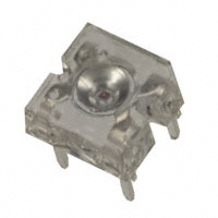
TELUX LED
FEATURES
• High luminous flux
• Supreme heat dissipation: RthJP is 90 K/W
• High operating temperature:
Tamb = -40 °C to +110 °C
• Meets SAE and ECE color requirements for the
automobile industry for color red
• Packed in tubes for automatic insertion
19232
• Luminous flux, forward voltage, and color
categorized for each tube
DESCRIPTION
The TELUX series is a clear, non diffused LED for
applications where supreme luminous flux is required.
• Small mechanical tolerances allow precise
usage of external reflectors or lightguides
It is designed in an industry standard 7.62 mm square
package utilizing highly developed (AS) AllnGaP technology.
• Compatible with wave solder processes according to
CECC 00802 and J-STD-020
The supreme heat dissipation of TELUX allows applications
at high ambient temperatures.
• ESD-withstand voltage: up to 2 kV according to
JESD 22-A114-B
All packing units are binned for luminous flux, forward
voltage, and color to achieve the most homogenous light
appearance in application.
• AEC-Q101 qualified
• Material categorization: for definitions of compliance
please see www.vishay.com/doc?99912
SAE and ECE color requirements for automobile application
are available for color red.
APPLICATIONS
ESD resistivity 2 kV (HBM) according to MIL STD 883D,
method 3015.7.
• Exterior lighting
• Dashboard illumination
PRODUCT GROUP AND PACKAGE DATA
• Tail-, stop-, and turn signals of motor vehicles
• Product group: LED
• Replaces small incandescent lamps
• Package: TELUX
• Traffic signals and signs
• Product series: power
• Angle of half intensity: ± 45°
PARTS TABLE
PART
LUMINOUS FLUX
(mlm)
COLOR
TLWR9900
Red
MIN.
TYP. MAX.
2500
3900
-
at IF
(mA)
70
WAVELENGTH
(nm)
MIN.
TYP. MAX.
611
616
634
at IF
(mA)
FORWARD VOLTAGE
(V)
70
MIN.
TYP.
MAX.
1.83
2.2
2.67
at IF
(mA)
TECHNOLOGY
70
AllnGaP on GaAs
ABSOLUTE MAXIMUM RATINGS (Tamb = 25 °C, unless otherwise specified)
TLWR9900
PARAMETER
Reverse voltage
DC forward current
Surge forward current
Power dissipation
TEST CONDITION
SYMBOL
VALUE
UNIT
IR = 100 μA
VR
10
V
mA
Tamb ≤ 85 °C
IF
70
tp ≤ 10 μs
IFSM
0.1
A
Tamb ≤ 85 °C
PV
187
mW
Junction temperature
Operating temperature range
Storage temperature range
Soldering temperature
Thermal resistance junction / ambient
Tj
125
°C
Tamb
-40 to +110
°C
Tstg
-55 to +110
°C
t ≤ 5 s, 1.5 mm from body preheat
temperature 100 °C / 30 s
Tsd
260
°C
With anode heatsink of 70 mm2
RthJA
200
K/W
Document Number: 83213
1
For technical questions, contact: LED@vishay.com
THIS DOCUMENT IS SUBJECT TO CHANGE WITHOUT NOTICE. THE PRODUCTS DESCRIBED HEREIN AND THIS DOCUMENT
ARE SUBJECT TO SPECIFIC DISCLAIMERS, SET FORTH AT www.vishay.com/doc?91000
Rev. 2.3, 07-Oct-15
�TLWR9900
www.vishay.com
Vishay Semiconductors
OPTICAL AND ELECTRICAL CHARACTERISTICS (Tamb = 25 °C, unless otherwise specified)
TLWR9900, RED
PARAMETER
TEST CONDITION
SYMBOL
MIN.
TYP.
MAX.
Total flux
IF = 70 mA, RthJA = 200 K/W
φV
2500
3900
-
UNIT
mlm
Luminous intensity/total flux
IF = 70 mA, RthJA = 200 K/W
IV/φV
-
0.5
-
mcd/mlm
Dominant wavelength
IF = 70 mA, RthJA = 200 K/W
λd
611
616
634
nm
Peak wavelength
IF = 70 mA, RthJA = 200 K/W
λp
-
624
-
nm
Angle of half intensity
IF = 70 mA, RthJA = 200 K/W
ϕ
-
± 45
-
deg
Total included angle
90 % of total flux captured
ϕ0.9 V
-
100
-
deg
IF = 70 mA, RthJA = 200 K/W
VF
1.83
2.2
2.67
V
VR
10
20
-
V
IF = 70 mA
TCλdom
-
0.07
-
nm/K
IF = 70 mA, T > -25 °C
TCVF
-
-2.9
-
mV/K
Forward voltage
Reverse voltage
Temperature coefficient of < λdom
Temperature coefficient of VF
FORWARD VOLTAGE CLASSIFICATION
GROUP
FORWARD VOLTAGE (V)
MIN.
MAX.
Y
1.83
2.07
Z
1.95
2.19
0
2.07
2.31
1
2.19
2.55
2
2.31
2.55
3
2.43
2.67
4
2.55
2.79
5
2.67
2.91
6
2.79
3.03
Note
• Voltages are tested at a current pulse duration of 1 ms and a
accuracy of ± 0.1 V.
COLOR CLASSIFICATION
GROUP
LUMINOUS FLUX CLASSIFICATION
GROUP
LUMINOUS FLUX (mlm)
MIN.
MAX.
E
2500
3600
F
3000
4200
G
3500
4800
Note
• Luminous flux is tested at a current pulse duration of 25 ms and
an accuracy of ± 11 %.
The above type numbers represent the order groups which
include only a few brightness groups. Only one group will be
shipped on each tube (there will be no mixing of two groups on
each tube).
In order to ensure availability, single brightness groups will be
not orderable.
In a similar manner for colors where wavelength groups are
measured and binned, single wavelength groups will be shipped
in any one tube.
In order to ensure availability, single wavelength groups will not
be orderable.
DOM. WAVELENGTH (nm)
MIN.
MAX.
1
611
618
2
614
622
3
616
634
Note
• Wavelengths are tested at a current pulse duration of 25 ms and
an accuracy of ± 1 nm.
Document Number: 83213
2
For technical questions, contact: LED@vishay.com
THIS DOCUMENT IS SUBJECT TO CHANGE WITHOUT NOTICE. THE PRODUCTS DESCRIBED HEREIN AND THIS DOCUMENT
ARE SUBJECT TO SPECIFIC DISCLAIMERS, SET FORTH AT www.vishay.com/doc?91000
Rev. 2.3, 07-Oct-15
�TLWR9900
www.vishay.com
Vishay Semiconductors
TYPICAL CHARACTERISTICS (Tamb = 25 °C, unless otherwise specified)
100
100
90
red
80
% Total Luminous Flux
IF - Forward Current (mA)
80
60
40
20
70
60
50
40
30
20
RthJA = 200 K/W
10
0
0
0
20
40
60
80
100
120
0
Tamb - Ambient Temperature (°C)
15983
0.12
230
0.10
220
75
100
125
Padsize 8 mm2
per anode pin
210
0.005
0.05
0.5
0.08
50
Fig. 4 - Percentage Total Luminous Flux vs.
Total Included Angle for 90° Emission Angle
RthJA (K/W)
I F - Forward Current (A)
Fig. 1 - Forward Current vs. Ambient Temperature
25
Total Included Angle (Degrees)
16201
0.06
0.04
200
190
180
0.02
170
0.00
10 -5
160
10 -4
10 -3
10 -2
10 -1
100
101
102
0
tp - Pulse Length (ms)
16731
16009
10°
100
150
200
250
300
Cathode Padsize (mm2)
Fig. 5 - Thermal Resistance Junction Ambient vs.
Cathode Padsize
Fig. 2 - Forward Current vs. Pulse Length
0°
50
20°
40°
1.0
0.9
50°
0.8
60°
70°
0.7
ϕ - Angular Displacement
IV rel. - Relative Luminous Intensity
30°
80°
0.6
0.4
0.2
0
16200
Fig. 3 - Rel. Luminous Intensity vs. Angular Displacement
Document Number: 83213
3
For technical questions, contact: LED@vishay.com
THIS DOCUMENT IS SUBJECT TO CHANGE WITHOUT NOTICE. THE PRODUCTS DESCRIBED HEREIN AND THIS DOCUMENT
ARE SUBJECT TO SPECIFIC DISCLAIMERS, SET FORTH AT www.vishay.com/doc?91000
Rev. 2.3, 07-Oct-15
�TLWR9900
www.vishay.com
Vishay Semiconductors
PACKAGE DIMENSIONS in millimeters
C
Cathode marking
technical drawings
according to DIN
specifications
Area not plane
5°
1.35 ± 0.1
SR1.65
A
0.6 max.
2.65 ± 0.3
4.65 ± 0.3
7.75 ± 0.3
1.45
1.6
1.32
0.76 ± 0.1
0.4 ± 0.1
5.08 ± 0.3
1.55 ± 0.2
7.62 ± 0.3
6.55
5.08 ± 0.2
7.62 ± 0.3
Drawing-No.: 6.544-5321.01-4
Issue: 5; 25.07.14
Document Number: 83213
4
For technical questions, contact: LED@vishay.com
THIS DOCUMENT IS SUBJECT TO CHANGE WITHOUT NOTICE. THE PRODUCTS DESCRIBED HEREIN AND THIS DOCUMENT
ARE SUBJECT TO SPECIFIC DISCLAIMERS, SET FORTH AT www.vishay.com/doc?91000
Rev. 2.3, 07-Oct-15
�Legal Disclaimer Notice
www.vishay.com
Vishay
Disclaimer
ALL PRODUCT, PRODUCT SPECIFICATIONS AND DATA ARE SUBJECT TO CHANGE WITHOUT NOTICE TO IMPROVE
RELIABILITY, FUNCTION OR DESIGN OR OTHERWISE.
Vishay Intertechnology, Inc., its affiliates, agents, and employees, and all persons acting on its or their behalf (collectively,
“Vishay”), disclaim any and all liability for any errors, inaccuracies or incompleteness contained in any datasheet or in any other
disclosure relating to any product.
Vishay makes no warranty, representation or guarantee regarding the suitability of the products for any particular purpose or
the continuing production of any product. To the maximum extent permitted by applicable law, Vishay disclaims (i) any and all
liability arising out of the application or use of any product, (ii) any and all liability, including without limitation special,
consequential or incidental damages, and (iii) any and all implied warranties, including warranties of fitness for particular
purpose, non-infringement and merchantability.
Statements regarding the suitability of products for certain types of applications are based on Vishay’s knowledge of
typical requirements that are often placed on Vishay products in generic applications. Such statements are not binding
statements about the suitability of products for a particular application. It is the customer’s responsibility to validate that a
particular product with the properties described in the product specification is suitable for use in a particular application.
Parameters provided in datasheets and / or specifications may vary in different applications and performance may vary over
time. All operating parameters, including typical parameters, must be validated for each customer application by the customer’s
technical experts. Product specifications do not expand or otherwise modify Vishay’s terms and conditions of purchase,
including but not limited to the warranty expressed therein.
Except as expressly indicated in writing, Vishay products are not designed for use in medical, life-saving, or life-sustaining
applications or for any other application in which the failure of the Vishay product could result in personal injury or death.
Customers using or selling Vishay products not expressly indicated for use in such applications do so at their own risk.
Please contact authorized Vishay personnel to obtain written terms and conditions regarding products designed for
such applications.
No license, express or implied, by estoppel or otherwise, to any intellectual property rights is granted by this document
or by any conduct of Vishay. Product names and markings noted herein may be trademarks of their respective owners.
Revision: 13-Jun-16
1
Document Number: 91000
�