TS53
www.vishay.com
Vishay Sfernice
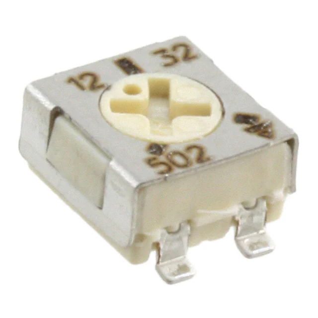
5 mm Square Surface Mount Miniature Trimmers Single-Turn
Cermet Sealed
FEATURES
• 0.25 W at 70 °C
• For through hole version see T53Y series
• Wide ohmic range (10 Ω to 1 MΩ)
• Small size for optimum packaging density
• Tests according to CECC 41000 or IEC 60393-1
• Material categorization: for definitions of compliance
please see www.vishay.com/doc?99912
LINKS TO ADDITIONAL RESOURCES
3D 3D
3D Models
The TS53 trimming potentiometer has been designed for
surface mount applications and offers volumetric efficiency
(5 mm x 5 mm x 2.7 mm) with high performance and
stability.
The TS53 design is suitable for both manual or automatic
operation, and can withstand wave, and reflow soldering
techniques.
DIMENSIONS in millimeters (± 0.25 mm)
RECOMMENDED
SOLDERING AREAS
TS53YL
TS53YJ
5
5
TS53YL
TS53YJ
0.20
2.7
2.7
0.20
2
6.4
5.5
0.75
1.1
2
b
1.3
b
2
1.3
5.5
4
1.3
2
1.3
c
0.9 x 0.20
1 x 0.20
a
b
A6
b
5
c
a
2.3
a
a
2.3
2.30
5
103
2.30
0.9 x 0.20
1 x 0.20
c
c
Cruciform screwdriver slot
Ø 2.5, width 0.5
Deep: 0.55
Max. deep (center): 0.7
Revision: 23-Mar-2021
Document Number: 51008
1
For technical questions, contact: sferpottrimmers@vishay.com
THIS DOCUMENT IS SUBJECT TO CHANGE WITHOUT NOTICE. THE PRODUCTS DESCRIBED HEREIN AND THIS DOCUMENT
ARE SUBJECT TO SPECIFIC DISCLAIMERS, SET FORTH AT www.vishay.com/doc?91000
�TS53
www.vishay.com
Vishay Sfernice
ELECTRICAL SPECIFICATIONS
Resistive element
Cermet
Electrical travel
220° ± 15°
10 Ω to 1 MΩ
Resistance range
Standard series
1-2-5
Tolerance standard
± 20 %
Circuit diagram
a
c
(1)
(3)
cw
b
(2)
linear
0.25 W at + 70 °C
0.25
Power rating
POWER IN W
0.20
0.15
0.10
0.05
0
0
20
40
60 70
100
120
140
155
AMBIENT TEMPERATURE IN °C
Temperature coefficient
See Standard Resistance Element Data table
Limiting element voltage (linear law)
200 V
Contact resistance variation (typical)
1 % or 3 Ω
End resistance (typical)
Dielectric strength (RMS)
Insulation resistance
0.1 % or 3 Ω
1000 V
1 GΩ
MECHANICAL SPECIFICATIONS
Mechanical travel
270 ° ± 10°
Operating torque (max. Ncm)
1.5
End stop torque (max. Ncm)
3.5
Unit weight (max. g)
Terminals
0.15
Pure Sn (e3)
ENVIRONMENTAL SPECIFICATIONS
Temperature range
Climatic category
Sealing
MSL level
-55 °C to +125 °C
55 / 125 / 56
Sealed container IP67
4
SOLDERING RECOMMENDATIONS
Recommended reflow profile 2, see Application Note www.vishay.com/doc?52029
Caution
Reflow soldering must be done within 72 h while stored under a max. temperature of 30 °C, 60 % RH after opening the dry pack envelope.
Revision: 23-Mar-2021
Document Number: 51008
2
For technical questions, contact: sferpottrimmers@vishay.com
THIS DOCUMENT IS SUBJECT TO CHANGE WITHOUT NOTICE. THE PRODUCTS DESCRIBED HEREIN AND THIS DOCUMENT
ARE SUBJECT TO SPECIFIC DISCLAIMERS, SET FORTH AT www.vishay.com/doc?91000
�TS53
www.vishay.com
Vishay Sfernice
RECOMMENDED METHOD OF STORAGE
Dry box storage is recommended as soon as the hermetic bag has been opened to prevent moisture absorption. The following conditions
should be observed, if dry boxes are not available:
• Storage temperature 10 °C to 30 °C
• Storage humidity ≤ 60 % RH max.
After more than 72 h under these conditions, moisture content will be too high for reflow soldering.
In case of moisture absorption, the devices will recover to the former condition by drying under the following condition:
192 h at 40 °C + 5 °C/- 0 °C and < 5 % RH (dry air/nitrogen) or
96 h at 60 °C + 5 °C and < 5 % RH for all device containers (not suitable for reel) or
24 h at 125 °C + 5 °C (not suitable for reel)
PERFORMANCES
TESTS
TYPICAL VALUES AND DRIFTS
CONDITIONS
ΔRT/RT (%)
ΔR1-2/R1-2 (%)
OTHER
Contact resistance variation:
ΔR < 1 % Rn
Electrical endurance
1000 h at rated power
90'/30' - ambient temp. 70 °C
±2%
±3%
Climatic sequence
Phase A dry heat 125 °C
Phase B damp heat
Phase C cold -55 °C
Phase D damp heat 5 cycles
±2%
±3%
Damp heat steady state
Temperature 40 °C - RH 93 %
56 days
±2%
±3%
Charge of temperature
-55 °C to +125 °C - 5 cycles
±1%
Mechanical endurance
100 cycles - rated power
± (3 % + 5 Ω)
50 g - 11 ms
3 successive shocks in 3 directions
±1%
ΔV1-2/V1-3 ≤ ± 1 %
10 Hz to 55 Hz
0.75 mm or 10 g - 6 h
±1%
ΔV1-2/V1-3 ≤ ± 1 %
Shock
Vibration
Dielectric strength: 1000 VRMS
Insulation resistance: > 104 MΩ
ΔV1-2/V1-3 ≤ ± 2 %
Note
• Nothing stated herein shall be construed as a guarantee of quality or durability.
STANDARD RESISTANCE ELEMENT DATA
STANDARD
RESISTANCE
VALUES
LINEAR LAW
MAX. POWER
AT 70 °C
MAX. WORKING
VOLTAGE
MAX. CURRENT
THROUGH ELEMENT
TYPICAL
TCR
-55 °C
+125 °C
ppm/°C
Ω
W
V
mA
10
0.25
1.58
158
20
0.25
2.24
112
50
0.25
3.54
71
100
0.25
5.00
50
200
0.25
7.07
35
500
0.25
11.2
22
1K
0.25
15.8
16
2K
0.25
22.4
11
5K
0.25
35.4
7
10K
0.25
50.0
5
20K
0.25
70.7
3.5
50K
0.25
112
2.2
100K
0.25
158
1.6
200K
0.20
200
1.0
500K
0.08
200
0.4
1M
0.04
200
0.2
Revision: 23-Mar-2021
± 100
Document Number: 51008
3
For technical questions, contact: sferpottrimmers@vishay.com
THIS DOCUMENT IS SUBJECT TO CHANGE WITHOUT NOTICE. THE PRODUCTS DESCRIBED HEREIN AND THIS DOCUMENT
ARE SUBJECT TO SPECIFIC DISCLAIMERS, SET FORTH AT www.vishay.com/doc?91000
�TS53
www.vishay.com
Vishay Sfernice
MARKING
Vishay trademark, ohmic value, manufacturing date
The ohmic value is indicated by a 3 figure code, the first two are significant figures, the third one is the multiplier.
Example: 100 = 10 Ω
101 = 100 Ω
102 = 1000 Ω
503 = 50 000 Ω
PACKAGING
On tape and reel of 500 pieces, code R10 (TR500) and 2000 pieces, code R20 (TR2000)
R10
R20
2
3 slots - width 2 mm,
each 120°
2
3 slots - width 2 mm,
each 120°
Ø 13.1
Ø 13.1
Ø 62
Ø 102
13
Ø 180
Ø 330
8
0.3
5.2
7.6
12
2
5.5
3.2
16.8
4
1.75
Ø 1.5
Cover tape panel strength specifications EIA 481 A and CEI 60286-3.
DRYPACK
Devices are packed in moisture barrier bags to prevent the products from moisture absorption during transportation and storage.
Each bag contains a desiccant.
ORDERING INFORMATION (part number)
T
S
5
3
Y
L
5
0
4
M
R
1
0
MODEL
STYLE
OHMIC VALUE
TOLERANCE
PACKAGING
TS53
YL
YJ
From 10 Ω to 1 MΩ
504 = 500 kΩ
M = 20 %
R10 =
reel 500 pieces
On request
R20 =
reel 2000 pieces
Revision: 23-Mar-2021
SPECIAL
NUMBER
(If applicable)
Given by Vishay
for custom design
Document Number: 51008
4
For technical questions, contact: sferpottrimmers@vishay.com
THIS DOCUMENT IS SUBJECT TO CHANGE WITHOUT NOTICE. THE PRODUCTS DESCRIBED HEREIN AND THIS DOCUMENT
ARE SUBJECT TO SPECIFIC DISCLAIMERS, SET FORTH AT www.vishay.com/doc?91000
�TS53
www.vishay.com
Vishay Sfernice
DESCRIPTION (for information only)
TS53
YL
500K
20 %
MODEL
STYLE
VALUE
TOLERANCE
SPECIAL
TR
e3
PACKAGING
LEAD (Pb)-FREE
RELATED DOCUMENTS
APPLICATION NOTES
Potentiometers and Trimmers
www.vishay.com/doc?51001
Guidelines for Vishay Sfernice Resistive and Inductive Components
www.vishay.com/doc?52029
Revision: 23-Mar-2021
Document Number: 51008
5
For technical questions, contact: sferpottrimmers@vishay.com
THIS DOCUMENT IS SUBJECT TO CHANGE WITHOUT NOTICE. THE PRODUCTS DESCRIBED HEREIN AND THIS DOCUMENT
ARE SUBJECT TO SPECIFIC DISCLAIMERS, SET FORTH AT www.vishay.com/doc?91000
�Legal Disclaimer Notice
www.vishay.com
Vishay
Disclaimer
ALL PRODUCT, PRODUCT SPECIFICATIONS AND DATA ARE SUBJECT TO CHANGE WITHOUT NOTICE TO IMPROVE
RELIABILITY, FUNCTION OR DESIGN OR OTHERWISE.
Vishay Intertechnology, Inc., its affiliates, agents, and employees, and all persons acting on its or their behalf (collectively,
“Vishay”), disclaim any and all liability for any errors, inaccuracies or incompleteness contained in any datasheet or in any other
disclosure relating to any product.
Vishay makes no warranty, representation or guarantee regarding the suitability of the products for any particular purpose or
the continuing production of any product. To the maximum extent permitted by applicable law, Vishay disclaims (i) any and all
liability arising out of the application or use of any product, (ii) any and all liability, including without limitation special,
consequential or incidental damages, and (iii) any and all implied warranties, including warranties of fitness for particular
purpose, non-infringement and merchantability.
Statements regarding the suitability of products for certain types of applications are based on Vishay's knowledge of typical
requirements that are often placed on Vishay products in generic applications. Such statements are not binding statements
about the suitability of products for a particular application. It is the customer's responsibility to validate that a particular product
with the properties described in the product specification is suitable for use in a particular application. Parameters provided in
datasheets and / or specifications may vary in different applications and performance may vary over time. All operating
parameters, including typical parameters, must be validated for each customer application by the customer's technical experts.
Product specifications do not expand or otherwise modify Vishay's terms and conditions of purchase, including but not limited
to the warranty expressed therein.
Hyperlinks included in this datasheet may direct users to third-party websites. These links are provided as a convenience and
for informational purposes only. Inclusion of these hyperlinks does not constitute an endorsement or an approval by Vishay of
any of the products, services or opinions of the corporation, organization or individual associated with the third-party website.
Vishay disclaims any and all liability and bears no responsibility for the accuracy, legality or content of the third-party website
or for that of subsequent links.
Except as expressly indicated in writing, Vishay products are not designed for use in medical, life-saving, or life-sustaining
applications or for any other application in which the failure of the Vishay product could result in personal injury or death.
Customers using or selling Vishay products not expressly indicated for use in such applications do so at their own risk. Please
contact authorized Vishay personnel to obtain written terms and conditions regarding products designed for such applications.
No license, express or implied, by estoppel or otherwise, to any intellectual property rights is granted by this document or by
any conduct of Vishay. Product names and markings noted herein may be trademarks of their respective owners.
© 2022 VISHAY INTERTECHNOLOGY, INC. ALL RIGHTS RESERVED
Revision: 01-Jan-2022
1
Document Number: 91000
�


 工商网监
湘ICP备2023018690号
工商网监
湘ICP备2023018690号

