TS63
www.vishay.com
Vishay Sfernice
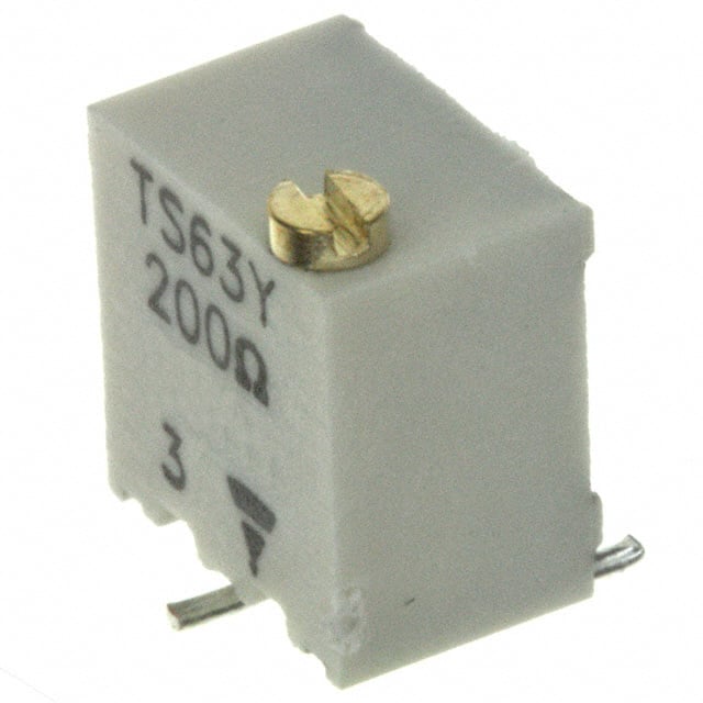
Multi-Turn Surface Mount 1/4" Square Cermet Trimmers,
Fully Sealed
FEATURES
• 0.25 W at 70 °C
• Industrial grade
• Multi-turn operation
• A low contact resistance variation (down to 2 % Rn)
DESIGN SUPPORT TOOLS
• Low end contact resistance (1 typical)
click logo to get started
• Full sealing
• Tests according to CECC 41000 or IEC 60393-1
Models
Available
The TS63 multiturn trimmer has been designed for use in
PCB surface mounting applications.
• Material categorization: for definitions of compliance
please see www.vishay.com/doc?99912
Three variations are available according to the positioning of
the control screw and contact positions.
The cermet track gives a high stability performance with an
extended ohmic capacity of 10 to 2 M.
DIMENSIONS in millimeters (± 0.5 mm)
RECOMMENDED
SOLDERING AREAS
TS63X
Slot 0.5 x 0.5
5.8 ± 0.10
1
0.25
5 max.
Ø 1.8
1 ± 0.10
c
2.54
0.7
c
b
b
2.54
2.54
Ø 0.45
6.85 max.
0.20
a
2.54
6.7 max.
6.85 max.
7.5
TS63Z
6.85 max.
Ø 1.8
3
Slot 0.5 x 0.5
1.3 ± 0.1
5 max.
b
9.3
1 ± 0.1
7.6 max.
0.25
6.85 max.
8.85 max.
a
c
Ø 0.45
1
5.3 max.
2.54
2.54
2.54
2.54
6.85 max.
TS63Y
c
0.3
a
Ø 0.45
1.3 ± 0.1
b
c
Slot 0.5 x 0.5
b
6.85
max.
2.54
2.54
Ø 1.8
8 max.
a
2.54
1 ± 0.10
Revision: 17-Oct-2018
2.54
5 max.
6.85 max.
6.7 max.
1
3
7.5
Document Number: 51011
1
For technical questions, contact: sferpottrimmers@vishay.com
THIS DOCUMENT IS SUBJECT TO CHANGE WITHOUT NOTICE. THE PRODUCTS DESCRIBED HEREIN AND THIS DOCUMENT
ARE SUBJECT TO SPECIFIC DISCLAIMERS, SET FORTH AT www.vishay.com/doc?91000
�TS63
www.vishay.com
Vishay Sfernice
ELECTRICAL SPECIFICATIONS
Resistive element
Cermet
Electrical travel
14 turns ± 2
10 to 2 M
Resistance range
Standard series
Tolerance
1-2-5
Standard
± 10 %
On request
±5%
a
Circuit diagram
c
(1)
(3)
b
(2)
Power rating
0.25 W at 70 °C
RATED POWER IN W
Linear
0.25
0.125
0
0
Temperature coefficient
cw
50
70
100
AMBIENT TEMPERATURE IN °C
155
See Standard Resistance Element Data table
Limiting element voltage
250 V
2 % Rn or 2
Contact resistance variation (typical)
1
End resistance (typical)
Dielectric strength (RMS)
1000 V
Insulation resistance
106 M
MECHANICAL SPECIFICATIONS
Mechanical travel
15 turns ± 5
Operating torque (max. Ncm)
1.5
End stop torque
Clutch action
Unit weight (max. g)
0.5
Wiper (actual travel)
Positioned at approx. 50 %
ENVIRONMENTAL SPECIFICATIONS
Temperature range
Climatic category
Sealing
MSL level
-55 °C to +155 °C
55/125/56
Sealed container
IP67
1
SOLDERING RECOMMENDATIONS
Recommended reflow profile 2, see Application Note www.vishay.com/doc?52029
Revision: 17-Oct-2018
Document Number: 51011
2
For technical questions, contact: sferpottrimmers@vishay.com
THIS DOCUMENT IS SUBJECT TO CHANGE WITHOUT NOTICE. THE PRODUCTS DESCRIBED HEREIN AND THIS DOCUMENT
ARE SUBJECT TO SPECIFIC DISCLAIMERS, SET FORTH AT www.vishay.com/doc?91000
�TS63
www.vishay.com
Vishay Sfernice
PERFORMANCES
TESTS
TYPICAL VALUES AND DRIFTS
CONDITIONS
RT/RT (%)
R1-2/R1-2 (%)
OTHER
Contact res. variation: < 1 % Rn
Electrical endurance
1000 h at rated power
90'/30' - ambient temp. 70 °C
±1%
±2%
Climatic sequence
Phase A dry heat 125 °C
Phase B damp heat
Phase C cold -55 °C
Phase D damp heat 5 cycles
±2%
±3%
Damp heat steady state
40 °C 93 % RH
56 days
±2%
±3%
Charge of temperature
-55 °C to +125 °C
5 cycles
±1%
V1-2/V1-3 ± 2 %
Mechanical endurance
200 cycles at rated power
± (2 % + 3 )
Contact res. variation: < 3 % Rn
50 g’s at 11 ms
3 successive shocks in 3 directions
±1%
V1-2/V1-3 1 %
10 Hz to 55 Hz
0.75 mm or 10 g’s
for 6 h
±1%
V1-2/V1-3 ± 2 %
Shock
Vibration
Dielectric strength: 1000 VRMS
Insulation resistance: > 104 M
Note
• Nothing stated herein shall be construed as a guarantee of quality or durability
STANDARD RESISTANCE ELEMENT DATA
STANDARD
RESISTANCE
VALUES
LINEAR LAW
MAX. POWER
AT 70 °C
MAX. WORKING
VOLTAGE
MAX. CURRENT
THROUGH WIPER
TYPICAL
TCR
-55 °C
+125 °C
ppm/°C
W
V
mA
10
0.25
1.58
158
20
0.25
2.23
112
50
0.25
3.53
77
100
0.25
5.00
50
200
0.25
7.07
35
500
0.25
11.2
22
1K
0.25
15.8
15.8
2K
0.25
22.3
11.2
5K
0.25
35.3
7.1
10K
0.25
50.0
5.0
20K
0.25
70.7
3.5
25K
0.25
79.0
3.2
50K
0.25
112
2.2
100K
0.25
158
1.6
200K
0.25
224
1.1
250K
0.25
250
1.1
500K
0.13
250
0.50
1M
0.06
250
0.25
2M
0.03
200
0.125
± 100
MARKING
Printed: VISHAY trademark, model, style, ohmic value (in , k, M), tolerance (in %) only if non standard, manufacturing date,
marking of terminal 3
Revision: 17-Oct-2018
Document Number: 51011
3
For technical questions, contact: sferpottrimmers@vishay.com
THIS DOCUMENT IS SUBJECT TO CHANGE WITHOUT NOTICE. THE PRODUCTS DESCRIBED HEREIN AND THIS DOCUMENT
ARE SUBJECT TO SPECIFIC DISCLAIMERS, SET FORTH AT www.vishay.com/doc?91000
�TS63
www.vishay.com
Vishay Sfernice
PACKAGING in millimeters
- X, Y and Z types: on tape and reel (dia. 330 mm) of 500 pieces, code TR500
- On request in magazine pack by 50 pieces (Tube) code TU
Version Z
Ø 13
22.4
Ø 330
16
3
Ø 1.5
Ø 1.5
12
Version X.Y
4
2
6
Ø 1.5 +- 0.1
0
12
4 2
0.3
2
1.8
16
0.3
12° max.
6.05
Ø 1.5
7.06
ORDERING INFORMATION (part number)
T
S
6
3
Y
5
0
4
K
R
1
0
MODEL
STYLE
OHMIC VALUE
TOLERANCE
PACKAGING
SPECIAL
NUMBER
TS63
X
Y
Z
From
10 to 2 M
504 = 500 k
K = ± 10 %
On request
J=±5%
R10 =
reel 500 pieces
On request
T20 =
tube 50 pieces
(If applicable)
Given by
Vishay
for custom
design
DESCRIPTION (for information only)
TS63
Y
500K
10 %
MODEL
STYLE
VALUE
TOLERANCE
SPECIAL
TR
e3
PACKAGING
LEAD FINISH
RELATED DOCUMENTS
APPLICATION NOTES
Potentiometers and Trimmers
www.vishay.com/doc?51001
Guidelines for Vishay Sfernice Resistive and Inductive Components
www.vishay.com/doc?52029
Revision: 17-Oct-2018
Document Number: 51011
4
For technical questions, contact: sferpottrimmers@vishay.com
THIS DOCUMENT IS SUBJECT TO CHANGE WITHOUT NOTICE. THE PRODUCTS DESCRIBED HEREIN AND THIS DOCUMENT
ARE SUBJECT TO SPECIFIC DISCLAIMERS, SET FORTH AT www.vishay.com/doc?91000
�Legal Disclaimer Notice
www.vishay.com
Vishay
Disclaimer
ALL PRODUCT, PRODUCT SPECIFICATIONS AND DATA ARE SUBJECT TO CHANGE WITHOUT NOTICE TO IMPROVE
RELIABILITY, FUNCTION OR DESIGN OR OTHERWISE.
Vishay Intertechnology, Inc., its affiliates, agents, and employees, and all persons acting on its or their behalf (collectively,
“Vishay”), disclaim any and all liability for any errors, inaccuracies or incompleteness contained in any datasheet or in any other
disclosure relating to any product.
Vishay makes no warranty, representation or guarantee regarding the suitability of the products for any particular purpose or
the continuing production of any product. To the maximum extent permitted by applicable law, Vishay disclaims (i) any and all
liability arising out of the application or use of any product, (ii) any and all liability, including without limitation special,
consequential or incidental damages, and (iii) any and all implied warranties, including warranties of fitness for particular
purpose, non-infringement and merchantability.
Statements regarding the suitability of products for certain types of applications are based on Vishay's knowledge of typical
requirements that are often placed on Vishay products in generic applications. Such statements are not binding statements
about the suitability of products for a particular application. It is the customer's responsibility to validate that a particular product
with the properties described in the product specification is suitable for use in a particular application. Parameters provided in
datasheets and / or specifications may vary in different applications and performance may vary over time. All operating
parameters, including typical parameters, must be validated for each customer application by the customer's technical experts.
Product specifications do not expand or otherwise modify Vishay's terms and conditions of purchase, including but not limited
to the warranty expressed therein.
Hyperlinks included in this datasheet may direct users to third-party websites. These links are provided as a convenience and
for informational purposes only. Inclusion of these hyperlinks does not constitute an endorsement or an approval by Vishay of
any of the products, services or opinions of the corporation, organization or individual associated with the third-party website.
Vishay disclaims any and all liability and bears no responsibility for the accuracy, legality or content of the third-party website
or for that of subsequent links.
Except as expressly indicated in writing, Vishay products are not designed for use in medical, life-saving, or life-sustaining
applications or for any other application in which the failure of the Vishay product could result in personal injury or death.
Customers using or selling Vishay products not expressly indicated for use in such applications do so at their own risk. Please
contact authorized Vishay personnel to obtain written terms and conditions regarding products designed for such applications.
No license, express or implied, by estoppel or otherwise, to any intellectual property rights is granted by this document or by
any conduct of Vishay. Product names and markings noted herein may be trademarks of their respective owners.
© 2022 VISHAY INTERTECHNOLOGY, INC. ALL RIGHTS RESERVED
Revision: 01-Jan-2022
1
Document Number: 91000
�