TSAL5300
www.vishay.com
Vishay Semiconductors
High Power Infrared Emitting Diode, 940 nm, GaAlAs/GaAs
FEATURES
•
•
•
•
•
•
•
•
•
•
•
•
•
96 11505
DESCRIPTION
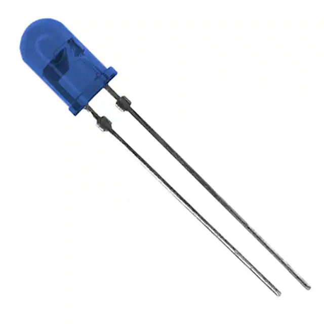
TSAL5300 is an infrared, 940 nm emitting diode in
GaAlAs/GaAs technology with high radiant power molded in
a blue-gray plastic package.
Package type: leaded
Package form: T-1¾
Dimensions (in mm): Ø 5
Leads with stand-off
Peak wavelength: λp = 940 nm
High reliability
High radiant power
High radiant intensity
Angle of half intensity: ϕ = ± 22°
Low forward voltage
Suitable for high pulse current operation
Good spectral matching with Si photodetectors
Compliant to RoHS Directive 2002/95/EC and in
accordance to WEEE 2002/96/EC
Note
** Please see document “Vishay Material Category Policy”:
www.vishay.com/doc?99902
APPLICATIONS
• Infrared remote control units with high power
requirements
• Free air transmission systems
• Infrared source for optical counters and card readers
PRODUCT SUMMARY
COMPONENT
Ie (mW/sr)
ϕ (deg)
λp (nm)
tr (ns)
45
± 22
940
800
TSAL5300
Note
• Test conditions see table “Basic Characteristics“
ORDERING INFORMATION
ORDERING CODE
TSAL5300
TSAL5300-MSZ
PACKAGING
REMARKS
PACKAGE FORM
Bulk
Tape and ammopack
MOQ: 4000 pcs, 4000 pcs/bulk
MOQ: 5000 pcs, 1000 pcs/ammopack
T-1¾
T-1¾
Note
• MOQ: minimum order quantity
ABSOLUTE MAXIMUM RATINGS (Tamb = 25 °C, unless otherwise specified)
SYMBOL
VALUE
Reverse voltage
PARAMETER
TEST CONDITION
VR
5
UNIT
V
Forward current
IF
100
mA
mA
Peak forward current
tp/T = 0.5, tp = 100 μs
IFM
200
Surge forward current
tp = 100 μs
IFSM
1.5
A
PV
160
mW
Power dissipation
Junction temperature
Tj
100
°C
Operating temperature range
Tamb
- 40 to + 85
°C
Storage temperature range
Tstg
- 40 to + 100
°C
t ≤ 5 s, 2 mm from case
Tsd
260
°C
J-STD-051, leads 7 mm soldered
on PCB
RthJA
230
K/W
Soldering temperature
Thermal resistance junction/ambient
Rev. 2.1, 24-Aug-11
Document Number: 81008
1
For technical questions, contact: emittertechsupport@vishay.com
THIS DOCUMENT IS SUBJECT TO CHANGE WITHOUT NOTICE. THE PRODUCTS DESCRIBED HEREIN AND THIS DOCUMENT
ARE SUBJECT TO SPECIFIC DISCLAIMERS, SET FORTH AT www.vishay.com/doc?91000
�TSAL5300
www.vishay.com
Vishay Semiconductors
120
160
IF - Forward Current (mA)
PV - Power Dissipation (mW)
180
140
120
100
RthJA = 230 K/W
80
60
40
100
80
RthJA = 230 K/W
60
40
20
20
0
0
0
10
21211
20 30
40
50
60
70 80
90
100
0
21212
Tamb - Ambient Temperature (°C)
Fig. 1 - Power Dissipation Limit vs. Ambient Temperature
10
20 30 40
50 60 70 80
90 100
Tamb - Ambient Temperature (°C)
Fig. 2 - Forward Current Limit vs. Ambient Temperature
BASIC CHARACTERISTICS (Tamb = 25 °C, unless otherwise specified)
PARAMETER
TEST CONDITION
SYMBOL
TYP.
MAX.
IF = 100 mA, tp = 20 ms
VF
1.35
1.6
V
IF = 1 A, tp = 100 μs
VF
2.6
3
V
Temperature coefficient of VF
IF = 1 mA
TKVF
- 1.8
Reverse current
VR = 5 V
IR
VR = 0 V, f = 1 MHz, E = 0
Cj
IF = 100 mA, tp = 20 ms
Ie
30
45
260
350
Forward voltage
Junction capacitance
Radiant intensity
Radiant power
Temperature coefficient of φe
MIN.
UNIT
mV/K
10
μA
150
mW/sr
25
pF
IF = 1 A, tp = 100 μs
Ie
IF = 100 mA, tp = 20 ms
φe
35
mW
IF = 20 mA
TKφe
- 0.6
%/K
ϕ
± 22
deg
nm
Angle of half intensity
mW/sr
Peak wavelength
IF = 100 mA
λp
940
Spectral bandwidth
IF = 100 mA
Δλ
50
nm
Temperature coefficient of λp
IF = 100 mA
TKλp
0.2
nm/K
IF = 100 mA
tr
800
ns
IF = 1 A
tr
500
ns
IF = 100 mA
tf
800
ns
IF = 1 A
tf
500
ns
Method: 63 % encircled energy
d
2.3
mm
Rise time
Fall time
Virtual source diameter
Rev. 2.1, 24-Aug-11
Document Number: 81008
2
For technical questions, contact: emittertechsupport@vishay.com
THIS DOCUMENT IS SUBJECT TO CHANGE WITHOUT NOTICE. THE PRODUCTS DESCRIBED HEREIN AND THIS DOCUMENT
ARE SUBJECT TO SPECIFIC DISCLAIMERS, SET FORTH AT www.vishay.com/doc?91000
�TSAL5300
www.vishay.com
Vishay Semiconductors
BASIC CHARACTERISTICS (Tamb = 25 °C, unless otherwise specified)
1000
Φ e - Radiant Power (mW)
I F - Forward Current (A)
10 1
IFSM = 1 A (Single Pulse)
t p/T = 0.01
0.05
10 0
0.1
0.5
1.0
10 -1
-2
10
96 11987
10 -1
10 0
10 1
t p - Pulse Duration (ms)
10
1
0.1
10 0
10 2
13602
Fig. 3 - Pulse Forward Current vs. Pulse Duration
104
1.6
103
1.2
102
tP = 100 µs
tP/T = 0.001
101
10 4
IF = 20 mA
0.8
0.4
100
0
1
2
3
0
- 10 0 10
4
VF - Forward Voltage (V)
13600
50
100
140
T amb - Ambient Temperature (°C)
94 7993
Fig. 4 - Forward Current vs. Forward Voltage
Fig. 7 - Relative Radiant Intensity/Power vs. Ambient Temperature
1000
1.25
Φe rel - Relative Radiant Power
I e - Radiant Intensity (mW/sr)
10 1
10 2
10 3
I F - Forward Current (mA)
Fig. 6 - Radiant Power vs. Forward Current
Ie rel; Φe rel
IF - Forward Current (mA)
100
100
10
1
1.0
0.75
0.5
0.25
IF = 100 mA
0
0.1
100
14327
101
102
103
I F - Forward Current (mA)
Fig. 5 - Radiant Intensity vs. Forward Current
Rev. 2.1, 24-Aug-11
890
104
14291
940
990
λ - Wavelength (nm)
Fig. 8 - Relative Radiant Power vs. Wavelength
Document Number: 81008
3
For technical questions, contact: emittertechsupport@vishay.com
THIS DOCUMENT IS SUBJECT TO CHANGE WITHOUT NOTICE. THE PRODUCTS DESCRIBED HEREIN AND THIS DOCUMENT
ARE SUBJECT TO SPECIFIC DISCLAIMERS, SET FORTH AT www.vishay.com/doc?91000
�TSAL5300
www.vishay.com
0°
10°
Vishay Semiconductors
20°
40°
1.0
0.9
50°
0.8
60°
70°
0.7
ϕ - Angular Displacement
Ie rel - Relative Radiant Intensity
30°
80°
0.6
94 8883
0.4
0.2
0
Fig. 9 - Relative Radiant Intensity vs. Angular Displacement
PACKAGE DIMENSIONS in millimeters
C
Ø 5.8 ± 0.15
A
很抱歉,暂时无法提供与“TSAL5300”相匹配的价格&库存,您可以联系我们找货
免费人工找货