TSOP852.., TSOP854..
Vishay Semiconductors
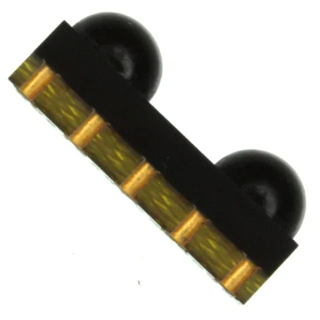
IR Receiver Modules for Remote Control Systems
FEATURES
• Very low supply current
• Photo detectors and preamplifier in one
package
• Internal filter for PCM frequency
• Supply voltage: 2.5 V to 5.5 V
• Improved immunity against ambient light
20427
• Capable of side or top view
• Two lenses for high sensitivity and wide receiving angle
• Component in accordance to RoHS 2002/95/EC and
WEEE 2002/96/EC
• Insensitive to supply voltage ripple and noise
DESCRIPTION
The TSOP852..,TSOP854 series are two lens miniaturized
receiver modules for infrared remote control systems. One
PIN diode per lens and a preamplifier are assembled on a
PCB, the epoxy lens cap is designed as an IR filter.
The demodulated output signal can be directly decoded by a
microprocessor. The TSOP852.. is compatible with all
common IR remote control data formats. The TSOP854.. is
optimized to suppress almost all spurious pulses from
energy saving fluorescent lamps but will also suppress some
data signals.
This component has not been qualified according to
automotive specifications.
PARTS TABLE
CARRIER FREQUENCY
STANDARD APPLICATIONS (AGC2/AGC8)
VERY NOISY ENVIRONMENTS (AGC4)
30 kHz
TSOP85230
TSOP85430
33 kHz
TSOP85233
TSOP85433
36 kHz
TSOP85236
TSOP85436
38 kHz
TSOP85238
TSOP85438
40 kHz
TSOP85240
TSOP85440
56 kHz
TSOP85256
TSOP85456
APPLICATION CIRCUIT
2
VS
30 kΩ
3
Input
AGC
Band
pass
Demodulator
OUT
17170_5
Transmitter
with
TSALxxxx
R1
IR receiver
VS
Circuit
BLOCK DIAGRAM
+ VS
C1
µC
OUT
GND
VO
GND
1, 4, 5
PIN
20445
www.vishay.com
230
Control circuit
GND
R1 and C1 are recommended for protection against EOS.
Components should be in the range of 33 Ω < R1 < 1 kΩ,
C1 > 0.1 µF.
Document Number: 81764
Revision: 1.1, 29-Jan-09
�TSOP852.., TSOP854..
IR Receiver Modules for
Remote Control Systems
Vishay Semiconductors
ABSOLUTE MAXIMUM RATINGS (1)
PARAMETER
SYMBOL
VALUE
Supply voltage
TEST CONDITION
VS
- 0.3 to + 6.0
V
Supply current
IS
3
mA
Output voltage
VO
- 0.3 to (VS + 0.3)
V
Output current
IO
5
mA
Tj
100
°C
Tstg
- 25 to + 85
°C
Tamb
- 25 to + 85
°C
Ptot
10
mW
Tsd
260
°C
Junction temperature
Storage temperature range
Operating temperature range
Tamb ≤ 85 °C
Power consumption
UNIT
Soldering temperature
Note
(1) Stresses beyond those listed under “Absolute Maximum Ratings” may cause permanent damage to the device. This is a stress rating only
and functional operation of the device at these or any other conditions beyond those indicated in the operational sections of this specification
is not implied. Exposure to absolute maximum rating condtions for extended periods may affect the device reliability.
ELECTRICAL AND OPTICAL CHARACTERISTICS (1)
PARAMETER
TEST CONDITION
SYMBOL
MIN.
VS
2.5
VS = 3.3 V, Ev = 0
ISD
0.27
Ev = 40 klx, sunlight
ISH
0.45
mA
Ev = 0
IR diode TSAL6200,
IF = 250 mA
test signal see fig. 1
d
45
m
Output voltage low
IOSL = 0.5 mA, Ee = 0.7 mW/m2,
test signal see fig. 1
VOSL
Minimum irradiance
Pulse width tolerance:
tpi - 5/fo < tpo < tpi + 6/fo
test signal see fig. 1
Ee min.
Maximum irradiance
tpi - 5/fo < tpo < tpi + 6/fo,
test signal see fig. 1
Ee max.
Angle of half transmission distance
ϕ1/2
Supply voltage
Supply current
Transmission distance
Directivity
TYP.
MAX.
0.35
0.1
UNIT
5.5
V
0.45
mA
100
mV
0.25
mW/m2
W/m2
30
± 50
deg
Note
(1) T
amb = 25 °C, unless otherwise specified
TYPICAL CHARACTERISTICS
Tamb = 25 °C, unless otherwise specified
1
Optical Test Signal
(IR diode TSAL6200, IF = 0.4 A, 30 pulses, f = f0, t = 10 ms)
t
tpi *
* tpi
VO
T
10/f0 is recommended for optimal function
Output Signal
1)
2)
VOH
16110
7/f0 < td < 15/f0
tpi - 5/f0 < tpo < tpi + 6/f 0
tpo - Output Pulse Width (ms)
Ee
Output Pulse Width
0.9
0.8
Input Burst Length
0.7
0.6
0.5
0.4
0.3
λ = 950 nm,
Optical Test Signal, Fig. 1
0.2
0.1
0
VOL
tpo2 )
td1 )
Fig. 1 - Output Active Low
Document Number: 81764
Revision: 1.1, 29-Jan-09
t
0.1
20743
1
10
100
1000
10 000
Ee - Irradiance (mW/m²)
Fig. 2 - Pulse Length and Sensitivity in Dark Ambient
www.vishay.com
231
�TSOP852.., TSOP854..
Optical Test Signal
Ee
600 µs
t
600 µs
t = 60 ms
94 8134
Output Signal, (see fig. 4)
VO
VOH
VOL
t on
Ee min. - Threshold Irradiance (mW/m²)
IR Receiver Modules for
Remote Control Systems
Vishay Semiconductors
4
Correlation with Ambient Light Sources:
3.5 10 W/m² = 1.4 klx (Std. illum. A, T = 2855 K)
10 W/m² = 8.2 klx (Daylight, T = 5900 K)
3
2
1.5
1
0.5
0
0.01
t
t off
Wavelength of Ambient
Illumination: λ = 950 nm
2.5
Ee min. - Threshold Irradiance (mW/m²)
Ton, Toff - Output Pulse Width (ms)
0.8
Ton
0.7
0.6
0.5
Toff
0.4
0.3
0.2
λ = 950 nm,
Optical Test Signal, Fig. 3
0
0.1
20744
1
10
100
1000
10
100
1
Ee - Irradiance (mW/m²)
f = 100 Hz
0.9
0.8
f = 10 kHz
0.7
0.6
f = 20 kHz
0.5
0.4
f = 30 kHz
0.3
0.2
f = f0
0.1
0
10 000
1
20746
10
100
1000
Δ VsRMS - AC Voltage on DC Supply Voltage (mV)
Fig. 7 - Sensitivity vs. Supply Voltage Disturbances
Fig. 4 - Output Pulse Diagram
500
E - Max. Field Strength (V/m)
1.2
1.0
E e min./Ee - Rel. Responsivity
1
Fig. 6 - Sensitivity in Bright Ambient
Fig. 3 - Output Function
0.1
0.1
Ee - Ambient DC Irradiance (W/m²)
20745
0.8
0.6
0.4
f = f0 ± 5 %
Δ f(3 dB) = f0/10
0.2
450
400
350
300
250
200
150
100
50
0
0.0
0.7
16925
0.9
1.1
1.3
f/f0 - Relative Frequency
Fig. 5 - Frequency Dependance of Responsivity
www.vishay.com
232
0
20747
500
1000
1500
2000
2500
3000
f - EMI Frequency (MHz)
Fig. 8 - Sensitivity vs. Electric Field Disturbances
Document Number: 81764
Revision: 1.1, 29-Jan-09
�TSOP852.., TSOP854..
IR Receiver Modules for
Remote Control Systems
Vishay Semiconductors
1
Max. Envelope Duty Cycle
0.9
0.8
0°
- 20°
0.7
0.6
- 40°
40°
0.5
TSOP852..
0.4
- 60°
60°
0.3
TSOP854..
0.2
- 80°
0.1
80°
f = 38 kHz, Ee = 2 mW/m²
0
20432
0
20817
20
40
60
80
100
0.1
0.3
0.5
0.7
0.9
120
Burst Length (number of cycles/burst)
Fig. 9 - Max. Envelope Duty Cycle vs. Burst Length
Ee min. - Threshold Irradiance (mW/m²)
20°
Fig. 12 - Directivity
0.2
0.18
0.16
0.14
0.12
0.1
0.08
0.06
0.04
0.02
0
- 30
- 10
10
30
50
70
90
Tamb - Ambient Temperature (°C)
20749
Fig. 10 - Sensitivity vs. Ambient Temperature
S( )rel - Relative Spectral Sensitivity
1.0
0.9
0.8
0.7
0.6
0.5
0.4
0.3
0.2
0.1
0
700 750 800 850 900 950 1000 1050 1100
20431
λ - Wavelength (nm)
Fig. 11 - Relative Spectral Sensitivity vs. Wavelength
Document Number: 81764
Revision: 1.1, 29-Jan-09
www.vishay.com
233
�TSOP852.., TSOP854..
Vishay Semiconductors
IR Receiver Modules for
Remote Control Systems
The TSOP852.., TSOP854 series are designed to suppress
spurious output pulses due to noise or disturbance signals.
Data and disturbance signals can be distinguished by the
devices according to carrier frequency, burst length and
envelope duty cycle. The data signal should be close to the
band-pass center frequency (e.g. 38 kHz) and fulfill the
conditions in the table below.
When a data signal is applied to the TSOP852.., TSOP854
in the presence of a disturbance signal, the sensitivity of the
receiver is reduced to insure that no spurious pulses are
present at the output. Some examples of disturbance signals
which are suppressed are:
IR Signal
SUITABLE DATA FORMAT
IR Signal from Fluorescent
Lamp with Low Modulation
• DC light (e.g. from tungsten bulb or sunlight)
• Continuous signals at any frequency
5
0
10
15
20
Time (ms)
16920
Fig. 13 - IR Signal from Fluorescent Lamp
with Low Modulation
• Strongly or weakly modulated noise from fluorescent
lamps with electronic ballasts (see figure 13 or figure 14)
IR Signal
IR Signal from Fluorescent
Lamp with High Modulation
0
10
10
15
20
Time (ms)
16921
Fig. 14 - IR Signal from Fluorescent Lamp
with High Modulation
TSOP852..
TSOP854..
Minimum burst length
10 cycles/burst
10 cycles/burst
After each burst of length
a minimum gap time is required of
10 to 70 cycles
≥ 10 cycles
10 to 35 cycles
≥ 10 cycles
For bursts greater than
a minimum gap time in the data stream is needed of
70 cycles
> 4 x burst length
35 cycles
> 10 x burst length
Maximum number of continuous short bursts/second
1800
1500
Recommended for NEC code
yes
yes
Recommended for RC5/RC6 code
yes
yes
Recommended for Sony code
yes
no
Recommended for Thomson 56 kHz code
yes
yes
Recommended for Mitsubishi code (38 kHz, preburst 8 ms, 16 bit)
yes
no
Recommended for Sharp code
yes
yes
Most common disturbance
signals are suppressed
Even extreme disturbance
signals are suppressed
Suppression of interference from fluorescent lamps
Note
For data formats with short bursts please see the data sheet for TSOP853..
www.vishay.com
234
Document Number: 81764
Revision: 1.1, 29-Jan-09
�TSOP852.., TSOP854..
IR Receiver Modules for
Remote Control Systems
Vishay Semiconductors
PACKAGE Dimensions in millimeters
20426
Document Number: 81764
Revision: 1.1, 29-Jan-09
www.vishay.com
235
�TSOP852.., TSOP854..
Vishay Semiconductors
IR Receiver Modules for
Remote Control Systems
TAPING VERSION TSOP..TR Dimensions in millimeters
20628
www.vishay.com
236
Document Number: 81764
Revision: 1.1, 29-Jan-09
�TSOP852.., TSOP854..
IR Receiver Modules for
Remote Control Systems
Vishay Semiconductors
TAPING VERSION TSOP..TT Dimensions in millimeters
20629
Document Number: 81764
Revision: 1.1, 29-Jan-09
www.vishay.com
237
�Legal Disclaimer Notice
Vishay
Disclaimer
All product specifications and data are subject to change without notice.
Vishay Intertechnology, Inc., its affiliates, agents, and employees, and all persons acting on its or their behalf
(collectively, “Vishay”), disclaim any and all liability for any errors, inaccuracies or incompleteness contained herein
or in any other disclosure relating to any product.
Vishay disclaims any and all liability arising out of the use or application of any product described herein or of any
information provided herein to the maximum extent permitted by law. The product specifications do not expand or
otherwise modify Vishay’s terms and conditions of purchase, including but not limited to the warranty expressed
therein, which apply to these products.
No license, express or implied, by estoppel or otherwise, to any intellectual property rights is granted by this
document or by any conduct of Vishay.
The products shown herein are not designed for use in medical, life-saving, or life-sustaining applications unless
otherwise expressly indicated. Customers using or selling Vishay products not expressly indicated for use in such
applications do so entirely at their own risk and agree to fully indemnify Vishay for any damages arising or resulting
from such use or sale. Please contact authorized Vishay personnel to obtain written terms and conditions regarding
products designed for such applications.
Product names and markings noted herein may be trademarks of their respective owners.
Document Number: 91000
Revision: 18-Jul-08
www.vishay.com
1
�