Datasheet Values Refer to PCN-OPT-1224-2022
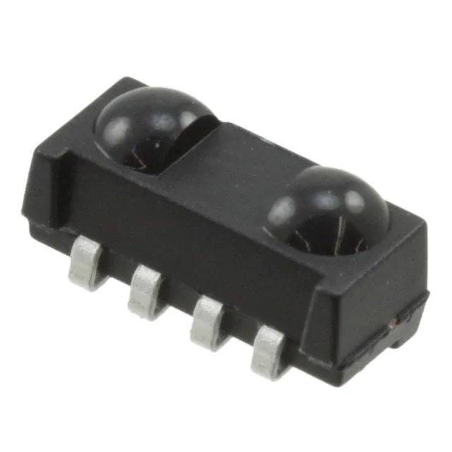
TSSP77P38
www.vishay.com
Vishay Semiconductors
IR Detector for Mid Range Proximity Sensor
DESCRIPTION
The TSSP77P38 is a compact infrared detector module for
proximity sensing application. It receives 38 kHz modulated
signals and has a peak sensitivity of 940 nm.
The length of the detector’s output pulse varies in proportion
to the amount of light reflected from the object being
detected.
FEATURES
•
•
•
•
•
•
•
•
•
Up to 2 m for proximity sensing
Very low supply current
Photo detector and preamplifier in one package
Shielding against EMI
Supply voltage: 2.0 V to 5.5 V
Visible light is suppressed by IR filter
Capable of side or top view
Insensitive to supply voltage ripple and noise
Two lenses for high sensitivity and wide
receiving angle
• Material categorization: for definitions of compliance
please see www.vishay.com/doc?99912
20953
APPLICATIONS
• Object approach detection for activation of displays and
user consoles, signaling of alarms, etc.
• Simple gesture controls
• Differentiation of car arrival, static, car departure in
parking lots
• Reflective sensors for toilet flush
• Navigational sensor for robotics
LINKS TO ADDITIONAL RESOURCES
Product Page
Marking
DESIGN SUPPORT TOOLS
• 3D models
• Window size calculator
BLOCK DIAGRAM
2
33 k Ω
VS
3
Input
AGC
Band
pass
Demodulator
OUT
1, 4
PIN
Control circuit
GND
20445-8
Rev. 2.6, 16-Aug-2022
1
Document Number: 82481
THIS DOCUMENT IS SUBJECT TO CHANGE WITHOUT NOTICE. THE PRODUCTS DESCRIBED HEREIN AND THIS DOCUMENT
ARE SUBJECT TO SPECIFIC DISCLAIMERS, SET FORTH AT www.vishay.com/doc?91000
�Datasheet Values Refer to PCN-OPT-1224-2022
TSSP77P38
www.vishay.com
Vishay Semiconductors
MECHANICAL DATA
ORDERING CODE
Pinning:
1, 4 = GND, 2 = VS, 3 = OUT
Taping:
TSSP77P38TT - top view taped, 2200 pcs/reel
TSSP77P38TR - side view taped, 2300 pcs/reel
PROXIMITY SENSING
+3 V
IR emitter
1
Envelope
signal
2
3
38 kHz
4
23207
+3 V
Out to
μC
IR detector
PARTS TABLE
Carrier frequency
38 kHz
TSSP77P38
Package
Heimdall
Pinning
1, 4 = GND, 2 = VS, 3 = OUT
Dimensions (mm)
6.8 W x 3.0 H x 3.2 D
Mounting
SMD
Application
Proximity sensors
Special options
• Extended temperature range: www.vishay.com/doc?82738
• Narrow optical filter: www.vishay.com/doc?81590
• Wide optical flter: www.vishay.com/doc?82726
ABSOLUTE MAXIMUM RATINGS
PARAMETER
SYMBOL
VALUE
Supply voltage
TEST CONDITION
VS
-0.3 to +6
V
Supply current
IS
5
mA
Output voltage
VO
-0.3 to (VS + 0.3)
V
Output current
IO
5
mA
Junction temperature
UNIT
Tj
100
°C
Storage temperature range
Tstg
-25 to +85
°C
Operating temperature range
Tamb
-25 to +85
°C
Ptot
10
mW
Power consumption
Tamb ≤ 85 °C
Note
• Stresses beyond those listed under “Absolute Maximum Ratings” may cause permanent damage to the device. This is a stress rating only
and functional operation of the device at these or any other conditions beyond those indicated in the operational sections of this specification
is not implied. Exposure to absolute maximum rating conditions for extended periods may affect the device reliability
Rev. 2.6, 16-Aug-2022
2
Document Number: 82481
THIS DOCUMENT IS SUBJECT TO CHANGE WITHOUT NOTICE. THE PRODUCTS DESCRIBED HEREIN AND THIS DOCUMENT
ARE SUBJECT TO SPECIFIC DISCLAIMERS, SET FORTH AT www.vishay.com/doc?91000
�Datasheet Values Refer to PCN-OPT-1224-2022
TSSP77P38
www.vishay.com
Vishay Semiconductors
ELECTRICAL AND OPTICAL CHARACTERISTICS (Tamb = 25 °C, unless otherwise specified)
PARAMETER
TEST CONDITION
Supply voltage
SYMBOL
MIN.
TYP.
MAX.
UNIT
VS
2.0
-
5.5
V
VS = 3.3 V, Ee = 0
ISD
0.25
0.35
0.45
mA
Ev = 40 klx, sunlight
ISH
-
0.45
-
mA
Receiving distance
Direct line of sight,
IR diode TSAL6200,
IF = 50 mA, test signal see Fig. 1
d
-
21
-
m
Output voltage low
IOSL = 0.5 mA, Ee = 0.7 mW/m2,
test signal see Fig. 1
VOSL
-
-
100
mV
Minimum irradiance
Pulse width tolerance:
tpi - 5/fo < tpo < tpi + 5/fo,
test signal see Fig. 1
Ee min.
-
0.15
0.3
mW/m2
Maximum irradiance
Pulse width tolerance:
tpi - 5/fo < tpo < tpi + 5/fo,
test signal see Fig. 1
Ee max.
30
-
-
W/m2
Angle of half receiving distance
ϕ1/2
-
± 50
-
°
Supply current
Directivity
TYPICAL CHARACTERISTICS (Tamb = 25 °C, unless otherwise specified)
Optical Test Signal
(IR diode TSAL6200, 30 pulses, f = f0, T = 10 ms)
1.0
0.9
E e min./Ee - Rel. Responsivity
Ee
t
tpi (1)
(1)
T
tpi ≥ 16/f0
Output Signal
(2)
11/f0 < td < 17/f0
VO
(3)
VOH
16110-17
tpi - 5/f0 < tpo < tpi + 5/f0
0.8
0.7
0.6
0.5
0.4
0.3
0.2
f = f0 ± 5 %
Δf (3 dB) = f0/10
0.1
0.0
25
VOL
td (2)
tpo (3)
30
t
Fig. 1 - Output Active Low
1000
0.6
Input burst length
0.4
100
0.3
λ = 950 nm,
optical test signal, Fig. 1
0.0
0.1
10
1000
10000
Correlation with ambient light sources:
10 W/m2 = 1.4 klx (std. ilum. A, T = 2855 K)
10 W/m2 = 8.2 klx (daylight, T = 5900 K)
3
Wavelength of ambient
illumination: λ = 950 nm
2
100
1
0
0.01
10
100 000
1000
1st line
2nd line
2nd line
Ee min. - Threshold Irradiance (mW/m2)
0.7
1st line
2nd line
2nd line
tpo - Output Pulse Width (ms)
0.8
0.1
10
0.1
1
10
Ee - Irradiance (mW/m2)
Ee - Ambient DC Irradiance (W/m2)
Fig. 2 - Pulse Length and Sensitivity in Dark Ambient
Fig. 4 - Sensitivity in Bright Ambient
Rev. 2.6, 16-Aug-2022
50
Axis Title
Output pulse width
0.2
45
4
10000
0.5
40
Fig. 3 - Frequency Dependence of Responsivity
Axis Title
1.0
0.9
35
f/f0 - Relative Frequency
3
100
Document Number: 82481
THIS DOCUMENT IS SUBJECT TO CHANGE WITHOUT NOTICE. THE PRODUCTS DESCRIBED HEREIN AND THIS DOCUMENT
ARE SUBJECT TO SPECIFIC DISCLAIMERS, SET FORTH AT www.vishay.com/doc?91000
�Datasheet Values Refer to PCN-OPT-1224-2022
TSSP77P38
www.vishay.com
Vishay Semiconductors
Axis Title
Axis Title
10000
0.7
0.6
0.5
1000
f = f0
f = 30 kHz
f = 10 kHz
f = 100 Hz
0.4
0.3
100
0.2
0.1
10
1000
0
1
10
100
10000
0.9
0.8
0.7
1000
0.6
1st line
2nd line
2nd line
S(λ)rel. - Relative Spectral Sensitivity
1.0
1st line
2nd line
2nd line
Ee min. - Threshold Irradiance (mW/m2)
0.8
0.5
0.4
100
0.3
0.2
0.1
10
1150
0
750
∆VS RMS - AC Voltage on DC Supply Voltage (mV)
850
1050
λ - Wavelength (nm)
21425
Fig. 5 - Sensitivity vs. Supply Voltage Disturbances
950
Fig. 8 - Relative Spectral Sensitivity vs. Wavelength
Axis Title
10000
200
Relative Response Distance
burst length 200ms,
burst repetition time 1s
1000
1st line
2nd line
2nd line
tpo - Output Pulse Width (ms)
1.2
dark
1 W/m² ambient DC light
10 W/m² ambient DC light
250
150
100
100
50
0.1
1
10
0.8
0.6
0.4
Directivity Characteristic of a
Reflective Sensor using
VSMB3940X01 and TSSP77P38
0.2
0
-90 -70 -50 -30 -10
10
0
1.0
100
10
30
50
70
90
Angle (°)
Ee - Irradiance (mW/m2)
Fig. 6 - Output Pulse Width vs. Irradiance
Fig. 9 - Angle Characteristic
Axis Title
10000
120
Emitter: VSMB1940X01
0.7
100
0.6
80
tpo (ms)
1000
0.5
1st line
2nd line
2nd line
Ee min. - Threshold Irradiance (mW/m2)
0.8
0.4
0.3
60
IF = 100 mA
40
100
0.2
20
IF = 10 mA
0.1
0
0.0
10
0
-30
-10
10
30
50
70
90
0.2
IF = 30 mA IF = 50 mA
0.4
0.6
0.8
1.0
1.2
Response Distance (m)
Tamb - Ambient Temperature (°C)
Fig. 10 - tpo vs. Distance Kodak Gray Card Plus 15 %
Fig. 7 - Sensitivity vs. Ambient Temperature
Rev. 2.6, 16-Aug-2022
4
Document Number: 82481
THIS DOCUMENT IS SUBJECT TO CHANGE WITHOUT NOTICE. THE PRODUCTS DESCRIBED HEREIN AND THIS DOCUMENT
ARE SUBJECT TO SPECIFIC DISCLAIMERS, SET FORTH AT www.vishay.com/doc?91000
�Datasheet Values Refer to PCN-OPT-1224-2022
TSSP77P38
www.vishay.com
Vishay Semiconductors
7
800
6
700
600
trepeat min. (ms)
dmax./dmin.
5
4
3
2
500
400
300
200
1
100
0
0
10 20 30 40 50 60 70 80 90 100 110 120
0
tpi (ms)
20
40
60
80 100 120 140 160 180
tpi (ms)
Fig. 11 - Dynamic Range of Sensor vs. tpi
Fig. 12 - Max. Rate of Bursts
The typical application of the TSSP77P38 is a reflective sensor with analog information contained in its output. Such a sensor
is evaluating the time required by the AGC to suppress a quasi continuous signal. The time required to suppress such a signal
is longer when the signal is strong than when the signal is weak, resulting in a pulse length corresponding to the distance of an
object from the sensor. This kind of analog information can be evaluated by a microcontroller. The absolute amount of reflected
light depends much on the environment and is not evaluated. Only sudden changes of the amount of reflected light, and
therefore changes in the pulse width, are evaluated using this application.
Example of a signal pattern:
trepeat = 500 ms
tpi = 120 ms, 38 kHz
Optical signal
Response of the
TSSP77P38
(strong reflection)
Response of the
TSSP77P38
(weak reflection)
Example for a sensor hardware:
The logarithmic characteristic of the AGC in the TSSP77P38
results in an almost linear relationship between distance and
pulse width. Ambient light has also some impact to the pulse
width of this kind of sensor, making the pulse shorter.
IR Receiver
TSSP77P38
Emitter
TSAL6200
Separation to avoid
crosstalk by stray light inside
the housing
There should be no common window in front of the emitter
and receiver in order to avoid crosstalk by guided light
through the window.
Rev. 2.6, 16-Aug-2022
5
Document Number: 82481
THIS DOCUMENT IS SUBJECT TO CHANGE WITHOUT NOTICE. THE PRODUCTS DESCRIBED HEREIN AND THIS DOCUMENT
ARE SUBJECT TO SPECIFIC DISCLAIMERS, SET FORTH AT www.vishay.com/doc?91000
�Datasheet Values Refer to PCN-OPT-1224-2022
TSSP77P38
www.vishay.com
Vishay Semiconductors
PACKAGE DIMENSIONS in millimeters
6.8
6.6 ± 0.1
3.2
(3.4)
Mold residue
Mold residue
2.5
(1.8)
1.2 ± 0.2
3
0.8
2.2
(0.635)
(1)
1.27
(3 x)
0.5 ± 0.1
(4 x)
technical drawings
according to DIN
specifications
3 x 1.27 = 3.81
Marking area
2.2
Not indicated tolerances ± 0.15
(1.65)
Tool separation line
(2.2)
Proposed pad layout
from component side
(for reference only)
3 x 1.27 = 3.81
1.27
Pick and place area
1.8
(R1.3)
Drawing-No.: 6.550-5297.01-4
Issue: 4; 13.09.11
0.8
22608
Rev. 2.6, 16-Aug-2022
6
Document Number: 82481
THIS DOCUMENT IS SUBJECT TO CHANGE WITHOUT NOTICE. THE PRODUCTS DESCRIBED HEREIN AND THIS DOCUMENT
ARE SUBJECT TO SPECIFIC DISCLAIMERS, SET FORTH AT www.vishay.com/doc?91000
�Datasheet Values Refer to PCN-OPT-1224-2022
TSSP77P38
www.vishay.com
Vishay Semiconductors
ASSEMBLY INSTRUCTIONS
Reflow Soldering
• Reflow soldering must be done within 72 h while stored
under a max. temperature of 30 °C, 60 % RH after
opening the dry pack envelope
• Set the furnace temperatures for pre-heating and heating
in accordance with the reflow temperature profile as
shown in the diagram. Exercise extreme care to keep the
maximum temperature below 260 °C. The temperature
shown in the profile means the temperature at the device
surface. Since there is a temperature difference between
the component and the circuit board, it should be verified
that the temperature of the device is accurately being
measured
• Handling after reflow should be done only after the work
surface has been cooled off
Manual Soldering
• Use a soldering iron of 25 W or less. Adjust the
temperature of the soldering iron below 300 °C
• Finish soldering within 3 s
• Handle products only after the temperature has cooled off
VISHAY LEAD (Pb)-FREE REFLOW SOLDER PROFILE
Axis Title
10000
300
max. 260 °C
255 °C
240 °C
245 °C
217 °C
1000
200
max. 20 s
1st line
2nd line
2nd line
Temperature (°C)
250
150
max. 120 s
max. 100 s
100
100
Max. ramp up 3 °C/s
50
Max. ramp down 6 °C/s
Max. 2 cycles allowed
10
0
0
19800
Rev. 2.6, 16-Aug-2022
50
100
150
200
250
300
Time (s)
7
Document Number: 82481
THIS DOCUMENT IS SUBJECT TO CHANGE WITHOUT NOTICE. THE PRODUCTS DESCRIBED HEREIN AND THIS DOCUMENT
ARE SUBJECT TO SPECIFIC DISCLAIMERS, SET FORTH AT www.vishay.com/doc?91000
�Datasheet Values Refer to PCN-OPT-1224-2022
TSSP77P38
www.vishay.com
Vishay Semiconductors
0.3
3.6
TAPING VERSION TSSP77P38TR DIMENSIONS in millimeters
16
7.5
1.75
1.34 ref.
Ø 1.5
4
Direction of feed
8
2
Ø 1.5 min.
technical drawings
according to DIN
specifications
Drawing-No.: 9.700-5337.01-4
Issue: 2; 06.10.15
Rev. 2.6, 16-Aug-2022
8
Document Number: 82481
THIS DOCUMENT IS SUBJECT TO CHANGE WITHOUT NOTICE. THE PRODUCTS DESCRIBED HEREIN AND THIS DOCUMENT
ARE SUBJECT TO SPECIFIC DISCLAIMERS, SET FORTH AT www.vishay.com/doc?91000
�Datasheet Values Refer to PCN-OPT-1224-2022
TSSP77P38
www.vishay.com
Vishay Semiconductors
3.65
0.3
TAPING VERSION TSSP77P38TT DIMENSIONS in millimeters
16
1.75
7.5
Ø 1.5
4
8
Direction of feed
2
Ø 1.5
technical drawings
according to DIN
specifications
Drawing-No.: 9.700-5338.01-4
Issue: 4; 12.06.13
Rev. 2.6, 16-Aug-2022
9
Document Number: 82481
THIS DOCUMENT IS SUBJECT TO CHANGE WITHOUT NOTICE. THE PRODUCTS DESCRIBED HEREIN AND THIS DOCUMENT
ARE SUBJECT TO SPECIFIC DISCLAIMERS, SET FORTH AT www.vishay.com/doc?91000
�Datasheet Values Refer to PCN-OPT-1224-2022
TSSP77P38
www.vishay.com
Vishay Semiconductors
REEL DIMENSIONS in millimeters
16734
LEADER AND TRAILER DIMENSIONS in millimeters
Trailer
no devices
Leader
devices
no devices
End
Start
min. 200
min. 400
96 11818
COVER TAPE PEEL STRENGTH
According to DIN EN 60286-3
0.1 N to 1.3 N
300 ± 10 mm/min.
165° to 180° peel angle
Rev. 2.6, 16-Aug-2022
10
Document Number: 82481
THIS DOCUMENT IS SUBJECT TO CHANGE WITHOUT NOTICE. THE PRODUCTS DESCRIBED HEREIN AND THIS DOCUMENT
ARE SUBJECT TO SPECIFIC DISCLAIMERS, SET FORTH AT www.vishay.com/doc?91000
�Datasheet Values Refer to PCN-OPT-1224-2022
TSSP77P38
www.vishay.com
Vishay Semiconductors
OUTER PACKAGING
The sealed reel is packed into a pizza box.
CARTON BOX DIMENSIONS in millimeters
Length
Thickness
Width
22127
Pizza box (SMD and heimdall)
(taping in reels)
THICKNESS
WIDTH
LENGTH
50
340
340
LABEL
Standard bar code labels for finished goods
The standard bar code labels are product labels and used for identification of goods. The finished goods are packed in final
packing area. The standard packing units are labeled with standard bar code labels before transported as finished goods to
warehouses. The labels are on each packing unit and contain Vishay Semiconductor GmbH specific data.
VISHAY SEMICONDUCTOR GmbH STANDARD BAR CODE PRODUCT LABEL (finished goods)
PLAIN WRITING
ABBREVIATION
LENGTH
Item-description
-
18
Item-number
INO
8
Selection-code
SEL
3
BATCH
10
Data-code
COD
3 (YWW)
Plant-code
PTC
2
Quantity
QTY
8
Accepted by
ACC
-
Packed by
PCK
-
MIXED CODE
-
xxxxxxx+
Company logo
TYPE
LENGTH
LOT-/serial-number
Mixed code indicator
Origin
LONG BAR CODE TOP
Item-number
N
8
Plant-code
N
2
Sequence-number
X
3
Quantity
N
8
Total length
-
21
TYPE
LENGTH
Selection-code
X
3
Data-code
N
3
Batch-number
X
10
Filter
-
1
Total length
-
17
SHORT BAR CODE BOTTOM
Rev. 2.6, 16-Aug-2022
11
Document Number: 82481
THIS DOCUMENT IS SUBJECT TO CHANGE WITHOUT NOTICE. THE PRODUCTS DESCRIBED HEREIN AND THIS DOCUMENT
ARE SUBJECT TO SPECIFIC DISCLAIMERS, SET FORTH AT www.vishay.com/doc?91000
�Datasheet Values Refer to PCN-OPT-1224-2022
TSSP77P38
www.vishay.com
Vishay Semiconductors
DRY PACKING
The reel is packed in an anti-humidity bag to protect the
devices from absorbing moisture during transportation and
storage.
LEVEL
CAUTION
This bag contains
MOISTURE-SENSITIVE DEVICES
Aluminum bag
4
1. Shelf life in sealed bag: 12 months at < 40 °C and < 90 % relative
humidity (RH)
2. After this bag is opened, devices that will be subjected to soldering
reflow or equivalent processing (peak package body temp. 260 °C)
must be
2a. Mounted within 72 hours at factory condition of < 30 °C/60 % RH or
2b. Stored at < 5 % RH
Label
3. Devices require baking befor mounting if:
Humidity Indicator Card is > 10 % when read at 23 °C ± 5 °C or
2a. or 2b. are not met.
4. If baking is required, devices may be baked for:
192 hours at 40 °C + 5 °C/- 0 °C and < 5 % RH (dry air/nitrogen) or
96 hours at 60 °C ± 5 °C and < 5 % RH for all device containers or
24 hours at 125 °C ± 5 °C not suitable for reels or tubes
Reel
Bag Seal Date:
(If blank, see barcode label)
15973
Note: Level and body temperature defined by EIA JEDEC Standard J-STD-020
22522
FINAL PACKING
EIA JEDEC standard J-STD-020 level 4 label is included
on all dry bags
The sealed reel is packed into a cardboard box.
ESD PRECAUTION
RECOMMENDED METHOD OF STORAGE
Proper storage and handling procedures should be followed
to prevent ESD damage to the devices especially when they
are removed from the antistatic shielding bag. Electrostatic
sensitive devices warning labels are on the packaging.
Dry box storage is recommended as soon as the aluminum
bag has been opened to prevent moisture absorption. The
following conditions should be observed, if dry boxes are
not available:
• Storage temperature 10 °C to 30 °C
• Storage humidity ≤ 60 % RH max.
After more than 72 h under these conditions moisture
content will be too high for reflow soldering.
In case of moisture absorption, the devices will recover to
the former condition by drying under the following condition:
192 h at 40 °C + 5 °C / - 0 °C and < 5 % RH (dry air /
nitrogen) or
96 h at 60 °C + 5 °C and < 5 % RH for all device containers
or
24 h at 125 °C + 5 °C not suitable for reel or tubes.
An EIA JEDEC® standard J-STD-020 level 4 label is included
on all dry bags.
VISHAY SEMICONDUCTORS STANDARD
BAR CODE LABELS (example)
The Vishay Semiconductors standard bar code labels are
printed at final packing areas. The labels are on each
packing unit and contain Vishay Semiconductors specific
data.
22178
Rev. 2.6, 16-Aug-2022
12
Document Number: 82481
THIS DOCUMENT IS SUBJECT TO CHANGE WITHOUT NOTICE. THE PRODUCTS DESCRIBED HEREIN AND THIS DOCUMENT
ARE SUBJECT TO SPECIFIC DISCLAIMERS, SET FORTH AT www.vishay.com/doc?91000
�Legal Disclaimer Notice
www.vishay.com
Vishay
Disclaimer
ALL PRODUCT, PRODUCT SPECIFICATIONS AND DATA ARE SUBJECT TO CHANGE WITHOUT NOTICE TO IMPROVE
RELIABILITY, FUNCTION OR DESIGN OR OTHERWISE.
Vishay Intertechnology, Inc., its affiliates, agents, and employees, and all persons acting on its or their behalf (collectively,
“Vishay”), disclaim any and all liability for any errors, inaccuracies or incompleteness contained in any datasheet or in any other
disclosure relating to any product.
Vishay makes no warranty, representation or guarantee regarding the suitability of the products for any particular purpose or
the continuing production of any product. To the maximum extent permitted by applicable law, Vishay disclaims (i) any and all
liability arising out of the application or use of any product, (ii) any and all liability, including without limitation special,
consequential or incidental damages, and (iii) any and all implied warranties, including warranties of fitness for particular
purpose, non-infringement and merchantability.
Statements regarding the suitability of products for certain types of applications are based on Vishay's knowledge of typical
requirements that are often placed on Vishay products in generic applications. Such statements are not binding statements
about the suitability of products for a particular application. It is the customer's responsibility to validate that a particular product
with the properties described in the product specification is suitable for use in a particular application. Parameters provided in
datasheets and / or specifications may vary in different applications and performance may vary over time. All operating
parameters, including typical parameters, must be validated for each customer application by the customer's technical experts.
Product specifications do not expand or otherwise modify Vishay's terms and conditions of purchase, including but not limited
to the warranty expressed therein.
Hyperlinks included in this datasheet may direct users to third-party websites. These links are provided as a convenience and
for informational purposes only. Inclusion of these hyperlinks does not constitute an endorsement or an approval by Vishay of
any of the products, services or opinions of the corporation, organization or individual associated with the third-party website.
Vishay disclaims any and all liability and bears no responsibility for the accuracy, legality or content of the third-party website
or for that of subsequent links.
Except as expressly indicated in writing, Vishay products are not designed for use in medical, life-saving, or life-sustaining
applications or for any other application in which the failure of the Vishay product could result in personal injury or death.
Customers using or selling Vishay products not expressly indicated for use in such applications do so at their own risk. Please
contact authorized Vishay personnel to obtain written terms and conditions regarding products designed for such applications.
No license, express or implied, by estoppel or otherwise, to any intellectual property rights is granted by this document or by
any conduct of Vishay. Product names and markings noted herein may be trademarks of their respective owners.
© 2022 VISHAY INTERTECHNOLOGY, INC. ALL RIGHTS RESERVED
Revision: 01-Jan-2022
1
Document Number: 91000
�