UIPMA, UIPMC
www.vishay.com
Vishay MCB
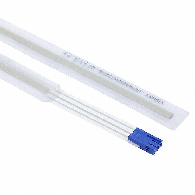
Displacement Sensor, Ultraflat Industrial Potentiometer Membrane
FEATURES
• Sealed IP66
• Infinite resolution
• High integration capacity
• Durability
• Rectilinear: UIPMA type
• Rotational: UIPMC type
• Material categorization: for definitions of compliance
please see www.vishay.com/doc?99912
LINKS TO ADDITIONAL RESOURCES
3D 3D
3D Models
Videos
QUICK REFERENCE DATA
Sensor type
LINEAR or ROTATIONAL, conductive plastic
Output type
Output by connector
Market appliance
Industrial
Dimensions
4 mm (thickness max.)
ELECTRICAL SPECIFICATIONS
PARAMETER
Total resistance (Rn)
Tolerance on Rn
Dissipation
Theoretical electrical travel (TET)
Tolerance on TET
Useful electrical travel (UET)
Electrical continuity travel (ECT)
Linearity
Temperature coefficient
Collector / track current (Ic)
Recommended current Ic
Recommended load impedance
Output smoothness
UIPMA
4.7 kΩ
UIPMC
10 kΩ
± 30 %
≤ 1 W to 70 °C
≤ 0.1 W/cm of travel (1)
312°
20 mm to 250 mm (1)
± 1 mm
± 3°
TET - 2 mm
306°
TET + 4 mm
325°
±2%
±5%
-300 ppm/°C ± 300 ppm/°C
≤ 1 mA
≤ 100 μA
≥ 100 Rn
< 0.1 % (NFC 93 255)
Note
(1) See “Specific UIPMA Characteristics” table
MECHANICAL SPECIFICATIONS
PARAMETER
Design
Mechanical travel
Backlash
Mounting
Speed displacement
Drive
Protection class (NFC 20 010)
Maximum alignment fault
UIPMA
UIPMC
Flexible insulating films
Flexible insulating films
Electrical continuity travel
Electrical continuity travel
< 0.1 mm
< 0.3°
With double-sided adhesive on flat, clean, and dry support
≤ 1.5 m/s
Force ≥ 0.3 N
Torque ≥ 1 N cm
IP66 (electrical connection and plug excluded)
± 1 mm
-
PERFORMANCE
PARAMETER
Life
Operating temperature range
Storage temperature range
Support
UIPMA
UIPMC
> 3M cycles (depending on chosen wiper)
-10 °C to +50 °C
-40 °C to +50 °C
Flat, clean, and dry
Note
• Nothing stated herein shall be construed as a guarantee of quality or durability
Revision: 30-Sep-2021
Document Number: 32537
1
For technical questions, contact: mcbprecisionpot@vishay.com
THIS DOCUMENT IS SUBJECT TO CHANGE WITHOUT NOTICE. THE PRODUCTS DESCRIBED HEREIN AND THIS DOCUMENT
ARE SUBJECT TO SPECIFIC DISCLAIMERS, SET FORTH AT www.vishay.com/doc?91000
�UIPMA, UIPMC
www.vishay.com
Vishay MCB
SAP PART NUMBERING GUIDELINES - UIPM
UIPMA: THEORETICAL ELECTRICAL TRAVEL (mm)
TYPE
VALUE LINEARITY LEADS PACKAGING
UIPMC: EXTERNAL DIAMETER (mm)
A = linear
050
I=
472 = 4K7 X = ± 2 %
C=
B = bulk
100 (on request)
industrial
connector
150
200 (on request)
250
C=
030
I=
103 = 10K
U
C=
B = bulk
rotational
industrial
connector
MODEL
TYPE
UIPM
UIPM
ACCESSORY WIPER
Wiper type A
Wiper type B
ACCSUIPMWIPERKB434
ACCSUFPMWIPERKB422
ACCSUIPMWIPERKB435 (packaging 10 pcs)
ACCSUIPMWIPERKG435 (packaging 100 pcs)
Wiper type D
CONNECTIONS
Connector Berg Duflex 67.013.003, contacts 76.785.301
The connector of UIPMA / UIPMC is intended for use with Berg terminal ref. 76785-YXX and Berg headers ref. 76384-YXX or 76382-YXX
DIMENSIONS in millimeters
UIPMA
TET + 14 ±1
6.5 ± 1
Bottom
Active area with adhesive
Connector Berg
Duflex 67013-003LF
Contacts 76785-301LF
Flat flex cable
0.51 ± 0.1 total thickness without protection layer
A Stuck on the customer interface
TET + flat flex cable + 14
C
TET + 11
1.75 ± 0.5
10 ± 1
B
13.5 ± 0.5
P
P in 3
Pi in 2
n
1
8 x R2 ± 1
7±1
Useful Electrical Travel:
UET (TET - 2)
Theoretical Electrical Travel
(TET)
Electrical Continuity Travel:
ECT (TET + 4)
Identification area: VISHAY - part number - date code
Part number: UIPMAxxxI472XCB
Date code: YYYYWW
(YYYY: the year of manufacture with 4 digits,
WW: week number with 2 digits)
Schematic (1)
Wiper
Usupply (pin 3)
Collector (pin 2)
Top
Top
Bottom
Warning:
do not bend the active area
Active area
Ground (pin 1)
Equipotential voltage areas
TET (mm)
50
100
150
200
250
FLAT FLEX CABLE (mm)
100
50
100
100
50
Notes
• Tolerancing according to ISO 8015
• General tolerances according to ISO 2768 - mK
(1) Ground and U
supply can be swapped to change the slope sign
Revision: 30-Sep-2021
Document Number: 32537
2
For technical questions, contact: mcbprecisionpot@vishay.com
THIS DOCUMENT IS SUBJECT TO CHANGE WITHOUT NOTICE. THE PRODUCTS DESCRIBED HEREIN AND THIS DOCUMENT
ARE SUBJECT TO SPECIFIC DISCLAIMERS, SET FORTH AT www.vishay.com/doc?91000
�UIPMA, UIPMC
www.vishay.com
Vishay MCB
MOUNTING REQUIREMENTS FOR UIPMA
1. The shape of the customer interface over the active area shall be:
0.05
2. The roughness of the customer interface over the active area shall be:
Ra 1.6
3. Before sticking the sensor, the interface surface shall be free of all traces of dirt, grease, foreign objects, and burrs.
4. The bending of the flat flex cable shall be: Ø 3 mm min.
DIMENSIONS in millimeters
Thickness 0.51 ± 0.1
without removal of
protection layer
UIPMC
Adhesive area
Back
15
Ø 30
Ø 24
Ø 18
Ø 12 (centering diameter)
UET
TET
R5 (x 2)
10
Active side
Pin 1
Pin 2
Pin 3
Connector:
Duflex HSNG SR1 100-2P3S
(Ref: 67013-003LF or alternative)
Duflex contact female
(Ref: 76785-301LF or alternative)
Pin 1
Pin 2
Pin 3
25
ELECTRICAL DIAGRAM
V+
Collector
GND
SPECIFIC VERSIONS (on request)
• Other electrical or mechanical characteristics
• Other bases
Yellow
• Integration in equipment
F
Red
• Other versions: outdoor design, ...
• Integration in equipment
(flat flex cable, contacts, wires, ...)
Green
The voltage varies according to the position of the presser
on the deformable membrane.
Revision: 30-Sep-2021
Document Number: 32537
3
For technical questions, contact: mcbprecisionpot@vishay.com
THIS DOCUMENT IS SUBJECT TO CHANGE WITHOUT NOTICE. THE PRODUCTS DESCRIBED HEREIN AND THIS DOCUMENT
ARE SUBJECT TO SPECIFIC DISCLAIMERS, SET FORTH AT www.vishay.com/doc?91000
�UIPMA, UIPMC
www.vishay.com
Vishay MCB
PRESSERS
Wiper Type A
Ø 4.3
Customer interface
Endurance life = 3M cycles
UIPMA
UIPMA support
10.5 ± 0.2 (working position)
Wiper Type B
UIPMA
UIPMA support
4.3 ± 0.1 (working position)
(15)
11 ± 0.1
Endurance life = 100 000 cycles
Ø 3.2 ± 0.1
6.5 ± 0.1
Wiper Type D (Endurance Life = 3M cycles)
Washer (not provided)
Customer wiper
interface
Screw (not provided)
Wiper
UIPMA
Customer UIPMA
interface
5.5 ± 0.1 (working position)
(15)
1:1
Ø 3.2 ± 0.1
10 ± 0.1
Ø5.5 ± 0.5
6 ± 0.1
Revision: 30-Sep-2021
Document Number: 32537
4
For technical questions, contact: mcbprecisionpot@vishay.com
THIS DOCUMENT IS SUBJECT TO CHANGE WITHOUT NOTICE. THE PRODUCTS DESCRIBED HEREIN AND THIS DOCUMENT
ARE SUBJECT TO SPECIFIC DISCLAIMERS, SET FORTH AT www.vishay.com/doc?91000
�UIPMA, UIPMC
www.vishay.com
Vishay MCB
SPECIFIC UIPMA CHARACTERISTICS
THEORETICAL ELECTRICAL
TRAVEL (TET) (mm)
DISSIPATION AT +40 °C
(W)
ELECTRICAL CONTINUITY TRAVEL (ECT)
(mm)
FILM LENGTH
(mm)
50
≤ 0.5
54
75
100
≤ 1.0
104
125
150
≤ 1.5
154
175
200
≤ 2.0
204
225
250
≤ 2.5
254
275
OPERATING DESCRIPTION
Presser
Deformable
membrane
(collector)
Insert
Support
membrane
(resistive track)
Collector / track
contact
ON REQUEST
UIPMA034 WITH WIRES OUTPUT
50 ± 0.5
42 ± 1
(useful area with adhesive surface)
+ (U2 / Red)
Bottom
Collector (U / Yellow)
Thickness 0.51 ± 0.1
without adhesive
layer protection
3.2 ± 0.2
Equipotential voltage area
A
Crimping area
with insulating
adhesive layer
Revision: 30-Sep-2021
Potting
Electrical continuity travel (ECT)
5 ± 0.5
Theoretical electrical travel
(TET)
150 ± 10
(6)
13.5 ± 0.5
Top
6.75 ± 0.25
Warning:
do not bend the product
in this direction
Detail A
4:1
U2
Potting
U1
Red
0.25 max. crimping area
Ground (U1 / Green)
2 max.
Wiper (to be define)
Yellow
Green
3 wires AWG26
Document Number: 32537
5
For technical questions, contact: mcbprecisionpot@vishay.com
THIS DOCUMENT IS SUBJECT TO CHANGE WITHOUT NOTICE. THE PRODUCTS DESCRIBED HEREIN AND THIS DOCUMENT
ARE SUBJECT TO SPECIFIC DISCLAIMERS, SET FORTH AT www.vishay.com/doc?91000
�UIPMA, UIPMC
www.vishay.com
Vishay MCB
ON REQUEST
UIPMA135 WITH WIRES OUTPUT
151 ± 0.5
143 ± 1 (useful area with adhesive surface)
+ (U2 / Red)
Bottom
Wiper (to be define)
Collector (U / Yellow)
A
3.2 ± 0.2
Equipotential voltage area
Crimping area
with insulating
adhesive layer
250 ± 10
3 wires AWG26
(6)
13.5 ± 0.5
Revision: 30-Sep-2021
Potting
Top
6.75 ± 0.25
Warning:
do not bend the product
in this direction
Detail A
4:1
5 ± 0.5
U2
U1
Theoretical electrical travel (TET)
Red
Potting
Yellow
Green
0.25 max. crimping area
Thickness 0.51 ± 0.1
without adhesive
layer protection
2 max.
Ground (U1 / Green)
Electrical continuity travel (ECT)
Document Number: 32537
6
For technical questions, contact: mcbprecisionpot@vishay.com
THIS DOCUMENT IS SUBJECT TO CHANGE WITHOUT NOTICE. THE PRODUCTS DESCRIBED HEREIN AND THIS DOCUMENT
ARE SUBJECT TO SPECIFIC DISCLAIMERS, SET FORTH AT www.vishay.com/doc?91000
�Legal Disclaimer Notice
www.vishay.com
Vishay
Disclaimer
ALL PRODUCT, PRODUCT SPECIFICATIONS AND DATA ARE SUBJECT TO CHANGE WITHOUT NOTICE TO IMPROVE
RELIABILITY, FUNCTION OR DESIGN OR OTHERWISE.
Vishay Intertechnology, Inc., its affiliates, agents, and employees, and all persons acting on its or their behalf (collectively,
“Vishay”), disclaim any and all liability for any errors, inaccuracies or incompleteness contained in any datasheet or in any other
disclosure relating to any product.
Vishay makes no warranty, representation or guarantee regarding the suitability of the products for any particular purpose or
the continuing production of any product. To the maximum extent permitted by applicable law, Vishay disclaims (i) any and all
liability arising out of the application or use of any product, (ii) any and all liability, including without limitation special,
consequential or incidental damages, and (iii) any and all implied warranties, including warranties of fitness for particular
purpose, non-infringement and merchantability.
Statements regarding the suitability of products for certain types of applications are based on Vishay's knowledge of typical
requirements that are often placed on Vishay products in generic applications. Such statements are not binding statements
about the suitability of products for a particular application. It is the customer's responsibility to validate that a particular product
with the properties described in the product specification is suitable for use in a particular application. Parameters provided in
datasheets and / or specifications may vary in different applications and performance may vary over time. All operating
parameters, including typical parameters, must be validated for each customer application by the customer's technical experts.
Product specifications do not expand or otherwise modify Vishay's terms and conditions of purchase, including but not limited
to the warranty expressed therein.
Hyperlinks included in this datasheet may direct users to third-party websites. These links are provided as a convenience and
for informational purposes only. Inclusion of these hyperlinks does not constitute an endorsement or an approval by Vishay of
any of the products, services or opinions of the corporation, organization or individual associated with the third-party website.
Vishay disclaims any and all liability and bears no responsibility for the accuracy, legality or content of the third-party website
or for that of subsequent links.
Except as expressly indicated in writing, Vishay products are not designed for use in medical, life-saving, or life-sustaining
applications or for any other application in which the failure of the Vishay product could result in personal injury or death.
Customers using or selling Vishay products not expressly indicated for use in such applications do so at their own risk. Please
contact authorized Vishay personnel to obtain written terms and conditions regarding products designed for such applications.
No license, express or implied, by estoppel or otherwise, to any intellectual property rights is granted by this document or by
any conduct of Vishay. Product names and markings noted herein may be trademarks of their respective owners.
© 2021 VISHAY INTERTECHNOLOGY, INC. ALL RIGHTS RESERVED
Revision: 09-Jul-2021
1
Document Number: 91000
�