VDMR10.0, VDMO10.0, VDMY10.0, VDMG10.0
www.vishay.com
Vishay Semiconductors
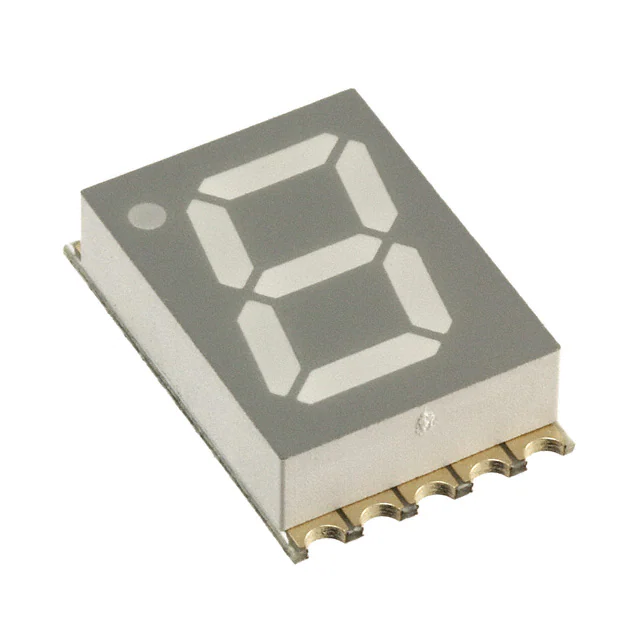
Standard 7-Segment SMD Display 10 mm
FEATURES
• Evenly lighted segments
• Grey package surface
• Untinted segments
• Luminous intensity categorized
• Yellow, green, and soft orange categorized for
color
• Wide viewing angle
• Suitable for DC and high peak current
DESCRIPTION
The VDM.10.0 series are 10 mm SMD seven segment LED
displays in a very compact package.
• Material categorization: For definitions of compliance
please see www.vishay.com/doc?99912
APPLICATIONS
The devices utilize AlInGaP on GaAs chip technology.
• Panel meters
PRODUCT GROUP AND PACKAGE DATA
• Test- and measure-equipment
• Product group: Display
• Point-of-sale terminals
• Package: 10 mm
• Control units
• Product series: SMD
• Angle of half intensity: ± 50°
PARTS TABLE
PART
COLOR
LUMINOUS INTENSITY
(μcd)
MIN.
TYP.
MAX.
WAVELENGTH
at
at FORWARD VOLTAGE at
(nm)
(V)
IF
IF
IF
(mA) MIN. TYP. MAX. (mA) MIN. TYP. MAX. (mA)
CIRCUITRY
VDMR10A0
Super red
180
650
-
1
-
631
-
20
-
2.0
2.6
20
Common anode
VDMR10C0
Super red
180
650
-
1
-
631
-
20
-
2.0
2.6
20
Common cathode
VDMO10A0
Soft orange
180
650
-
1
-
605
-
20
-
2.0
2.6
20
Common anode
VDMO10C0
Soft orange
180
650
-
1
-
605
-
20
-
2.0
2.6
20
Common cathode
VDMY10A0
Yellow
1100
2750
-
1
-
589
-
20
-
2.0
2.6
20
Common anode
VDMY10C0
Yellow
1100
2750
-
1
-
589
-
20
-
2.0
2.6
20
Common cathode
VDMG10A0
Green
110
400
-
1
-
572
-
20
-
2.0
2.6
20
Common anode
VDMG10C0
Green
110
400
-
1
-
572
-
20
-
2.0
2.6
20
Common cathode
ABSOLUTE MAXIMUM RATINGS (Tamb = 25 °C, unless otherwise specified)
VDMR10.0, VDMO10.0, VDMY10.0, VDMG10.0
PARAMETER
SYMBOL
VALUE
UNIT
Power dissipation per segment
TEST CONDITION
PV
70
mW
Peak forward current per segment
(frequency 1 kHz, 10 % duty cycle)
IF
60
mA
Continous forward current per segment
IF
Forward current derating from 25 °C
25
mA
0.28
mA/°C
Operating temperature range
Tamb
-35 to +105
°C
Storage temperature range
Tstg
-35 to +105
°C
Iron soldering conditions: 1/16" below seating plane for 3 s at 260 °C
Rev. 1.2, 29-Nov-13
Document Number: 84196
1
For technical questions, contact: LED@Vishay.com
THIS DOCUMENT IS SUBJECT TO CHANGE WITHOUT NOTICE. THE PRODUCTS DESCRIBED HEREIN AND THIS DOCUMENT
ARE SUBJECT TO SPECIFIC DISCLAIMERS, SET FORTH AT www.vishay.com/doc?91000
�VDMR10.0, VDMO10.0, VDMY10.0, VDMG10.0
www.vishay.com
Vishay Semiconductors
OPTICAL AND ELECTRICAL CHARACTERISTICS (Tamb = 25 °C, unless otherwise specified)
VDMR10A0, VDMR10C0, SUPER RED
PARAMETER
TEST CONDITION
IF = 1 mA
Luminous intensity (1)
IF = 10 mA
PART
VDMR10A0
VDMR10C0
VDMR10A0
VDMR10C0
SYMBOL
MIN.
TYP.
MAX.
UNIT
IV
180
650
-
μcd
IV
-
8250
-
μcd
Dominant wavelength
IF = 20 mA
λd
-
631
-
nm
Peak emmision wavelength
IF = 20 mA
λp
-
639
-
nm
Spectral line half-width
IF = 10 mA
Δλ
-
20
-
Forward voltage per segment
IF = 20 mA
Reverse current per segment (2)
Luminous intensity matching ratio
VDMR10A0,
VDMR10C0
VF
-
2.0
2.6
V
VR = 5 V
IR
-
-
100
μA
IF = 10 mA
Iv-m
-
-
2:1
Notes
(1) Luminous intensity is measured with a light sensor and filter combination that approximates the CIE eye-response curve.
(2) Reverse voltage is only for IR test.It can not continue to operate at this situation.
(3) Cross talk specification ≤ 2.5 %.
OPTICAL AND ELECTRICAL CHARACTERISTICS (Tamb = 25 °C, unless otherwise specified)
VDMO10A0, VDMO10C0, SOFT ORANGE
PARAMETER
TEST CONDITION
IF = 1 mA
Luminous intensity (1)
IF = 10 mA
PART
VDMO10A0
VDMO10C0
VDMO10A0
VDMO10C0
SYMBOL
MIN.
TYP.
MAX.
UNIT
IV
180
650
-
μcd
IV
-
8250
-
μcd
Dominant wavelength
IF = 20 mA
λd
-
605
-
nm
Peak emmision wavelength
IF = 20 mA
λp
-
611
-
nm
Spectral line half-width
IF = 10 mA
Δλ
-
17
-
Forward voltage per segment
IF = 20 mA
Reverse current per segment (2)
Luminous intensity matching ratio
VDMO10A0,
VDMO10C0
VF
-
2.0
2.6
V
VR = 5 V
IR
-
-
100
μA
IF = 10 mA
Iv-m
-
-
2:1
Notes
(1) Luminous intensity is measured with a light sensor and filter combination that approximates the CIE eye-response curve.
(2) Reverse voltage is only for IR test.It can not continue to operate at this situation.
(3) Cross talk specification ≤ 2.5 %.
OPTICAL AND ELECTRICAL CHARACTERISTICS (Tamb = 25 °C, unless otherwise specified)
VDMY10A0, VDMY10C0, YELLOW
PARAMETER
TEST CONDITION
IF = 1 mA
Luminous intensity (1)
IF = 10 mA
PART
VDMY10A0
VDMY10C0
VDMY10A0
VDMY10C0
SYMBOL
MIN.
TYP.
MAX.
UNIT
IV
1100
2750
-
μcd
IV
-
30 250
-
μcd
Dominant wavelength
IF = 20 mA
λd
-
589
-
nm
Peak emmision wavelength
IF = 20 mA
λp
-
588
-
nm
Spectral line half-width
IF = 10 mA
Δλ
-
15
-
Forward voltage per segment
IF = 20 mA
Reverse current per segment (2)
Luminous intensity matching ratio
VDMY10A0,
VDMY10C0
VF
-
2.0
2.6
V
VR = 5 V
IR
-
-
100
μA
IF = 10 mA
Iv-m
-
-
2:1
Notes
(1) Luminous intensity is measured with a light sensor and filter combination that approximates the CIE eye-response curve.
(2) Reverse voltage is only for IR test.It can not continue to operate at this situation.
(3) Cross talk specification ≤ 2.5 %.
Rev. 1.2, 29-Nov-13
Document Number: 84196
2
For technical questions, contact: LED@Vishay.com
THIS DOCUMENT IS SUBJECT TO CHANGE WITHOUT NOTICE. THE PRODUCTS DESCRIBED HEREIN AND THIS DOCUMENT
ARE SUBJECT TO SPECIFIC DISCLAIMERS, SET FORTH AT www.vishay.com/doc?91000
�VDMR10.0, VDMO10.0, VDMY10.0, VDMG10.0
www.vishay.com
Vishay Semiconductors
OPTICAL AND ELECTRICAL CHARACTERISTICS (Tamb = 25 °C, unless otherwise specified)
VDMG10A0, VDMG10C0, GREEN
PARAMETER
TEST CONDITION
IF = 1 mA
Luminous intensity (1)
IF = 10 mA
PART
SYMBOL
MIN.
TYP.
MAX.
UNIT
IV
110
400
-
μcd
IV
-
4400
-
μcd
VDMG10A0
VDMG10C0
VDMG10A0
VDMG10C0
Dominant wavelength
IF = 20 mA
λd
-
572
-
nm
Peak emmision wavelength
IF = 20 mA
λp
-
571
-
nm
Spectral line half-width
IF = 10 mA
Δλ
-
15
-
Forward voltage per segment
IF = 20 mA
Reverse current per segment (2)
Luminous intensity matching ratio
VDMG10A0,
VDMG10C0
VF
-
2.0
2.6
V
VR = 5 V
IR
-
-
100
μA
IF = 10 mA
Iv-m
-
-
2:1
Notes
(1) Luminous intensity is measured with a light sensor and filter combination that approximates the CIE eye-response curve.
(2) Reverse voltage is only for IR test.It can not continue to operate at this situation.
(3) Cross talk specification ≤ 2.5 %.
LUMINOUS INTENSITY CLASSIFICATION
GROUP
LIGHT INTENSITY (μcd)
COLOR CLASSIFICATION
GROUP
SOFT ORANGE
YELLOW
GREEN
MIN.
MAX.
MIN.
MAX.
MIN.
MAX.
1
598
601
581
584
-
-
360
2
600
603
583
586
-
-
280
560
3
602
605
585
588
562
565
450
900
4
604
607
587
590
564
567
H
700
1400
5
606
609
589
592
566
569
I
1100
2200
6
608
611
591
594
568
571
K
1800
3600
7
-
-
-
-
570
573
8
-
-
-
-
572
575
STANDARD
MIN.
MAX.
D
110
220
E
180
F
G
L
2800
5600
M
4500
9000
N
7000
14 000
P
11 000
22 000
Q
18 000
36 000
R
28 000
56 000
S
45 000
90 000
Note
• Wavelengths are tested at a current pulse duration of 25 ms.
Note
• The above type numbers represent the order groups which
include only a few brightness groups. Only one group will be
shipped in one tube (there will be no mixing of two groups in one
tube).
In order to ensure availability, single brightness groups will not
be orderable.
Rev. 1.2, 29-Nov-13
Document Number: 84196
3
For technical questions, contact: LED@Vishay.com
THIS DOCUMENT IS SUBJECT TO CHANGE WITHOUT NOTICE. THE PRODUCTS DESCRIBED HEREIN AND THIS DOCUMENT
ARE SUBJECT TO SPECIFIC DISCLAIMERS, SET FORTH AT www.vishay.com/doc?91000
�VDMR10.0, VDMO10.0, VDMY10.0, VDMG10.0
www.vishay.com
Vishay Semiconductors
TYPICAL CHARACTERISTICS (Tamb = 25 °C, unless otherwise specified)
100
I F - Forward Current (mA)
IF - Forward Current (mA)
30
25
20
15
10
10
5
0
0
20
40
60
80
100
1
1.0
120
Tamb - Ambient Temperature (°C)
green
2.5
3.0
3.5
Fig. 4 - Forward Current vs. Forward Voltage
100
yellow soft orange
super red
Ipeak - Peak Current (mA)
1.0
Irel - Relative Intensity
2.0
V F - Forward Voltage (V)
Fig. 1 - Forward Current vs. Ambient Temperature
1.2
1.5
0.8
0.6
0.4
0.2
0
520 540 560 580 600 620 640 660 680
λ - Wavelength (nm)
Fig. 2 - Relative Intensity vs. Wavelength
10
1
10
100
Duty Cycle % (Frequency 1 kHz)
Fig. 5 - Peak Current vs. Duty Cycle
I v rel - Relative Luminous Intensity
(normalized to 1 at 10 mA)
3.0
2.5
2.0
1.5
1.0
0.5
0
0
5
10
15
20
25
30
I F - Forward Current (mA)
Fig. 3 - Relative Luminous Intensity vs. Forward Current
Rev. 1.2, 29-Nov-13
Document Number: 84196
4
For technical questions, contact: LED@Vishay.com
THIS DOCUMENT IS SUBJECT TO CHANGE WITHOUT NOTICE. THE PRODUCTS DESCRIBED HEREIN AND THIS DOCUMENT
ARE SUBJECT TO SPECIFIC DISCLAIMERS, SET FORTH AT www.vishay.com/doc?91000
�VDMR10.0, VDMO10.0, VDMY10.0, VDMG10.0
www.vishay.com
Vishay Semiconductors
PACKAGE DIMENSIONS in millimeters
6. 2
3.75
1. 2
10
0.6
1.9
6
10
5
1
4.5
10
15
13
6
1
10°
1.55 ±0.1
9.8
Ø1.2
5
R0.65
1
Plastic pins’ burr max. 0.14 mm
PART NO
DATE CODE
BIN CODE
3, 8 (C)
3, 8 (A)
A
F
G
E
B
A B C D E F G DP
A B C D E F G DP
C
D
DP
7 6 4 2 1 9 10 5
7 6 4 2 1 9 10 5
Tolerances are ± 0.25 mm unless otherwise mentioned
technical drawings
according to DIN
specifications
Drawing-No.: 6.544-5425.01-4
Issue: 2; 02.10.13
Rev. 1.2, 29-Nov-13
Document Number: 84196
5
For technical questions, contact: LED@Vishay.com
THIS DOCUMENT IS SUBJECT TO CHANGE WITHOUT NOTICE. THE PRODUCTS DESCRIBED HEREIN AND THIS DOCUMENT
ARE SUBJECT TO SPECIFIC DISCLAIMERS, SET FORTH AT www.vishay.com/doc?91000
�VDMR10.0, VDMO10.0, VDMY10.0, VDMG10.0
www.vishay.com
Vishay Semiconductors
TAPE AND REEL DIMENSIONS in millimeters
TAPE IN BOX
Rev. 1.2, 29-Nov-13
Document Number: 84196
6
For technical questions, contact: LED@Vishay.com
THIS DOCUMENT IS SUBJECT TO CHANGE WITHOUT NOTICE. THE PRODUCTS DESCRIBED HEREIN AND THIS DOCUMENT
ARE SUBJECT TO SPECIFIC DISCLAIMERS, SET FORTH AT www.vishay.com/doc?91000
�VDMR10.0, VDMO10.0, VDMY10.0, VDMG10.0
www.vishay.com
Vishay Semiconductors
BAR CODE PRODUCT LABEL (example only)
RECOMMENDED SOLDER PAD
4 x 1.9 = 7.6
A
3
B
C
D
L
E
I
G
F
H
M
K
2D barcode
Vishay part number
Quantity
PTC = selection code (binning)
Code of manufacturing plant
Batch = date code: year/week/plant code
Region code
SL = sales location
Terminations finishing
Lead (Pb)-free symbol
Halogen-free symbol
RoHS symbol
15
A)
B)
C)
D)
E)
F)
G)
H)
I)
K)
L)
M)
1.65
MSL LABEL
SOLDERING PROFILE
IR Reflow Soldering Profile for lead (Pb)-free Soldering
Preconditioning acc. to JEDEC Level 3
300
Temperature (°C)
max. 260 °C
245 °C
255
255 °C
240 °C
217 °C
250
200
max. 30 s
150
max. 100 s
max. 120 s
100
max. Ramp Up 3 °C/s
50
max. Ramp Down 6 °C/s
0
0
50
19470-5
100
150
Time (s)
200
250
300
max. 2 cycles allowed
Fig. 6 - Vishay Lead (Pb)-free Reflow Soldering Profile
(acc. to J-STD-020C)
SOLDERING IRON (one time only)
Temperature
Soldering time
Rev. 1.2, 29-Nov-13
300 °C max.
3 s max.
Document Number: 84196
7
For technical questions, contact: LED@Vishay.com
THIS DOCUMENT IS SUBJECT TO CHANGE WITHOUT NOTICE. THE PRODUCTS DESCRIBED HEREIN AND THIS DOCUMENT
ARE SUBJECT TO SPECIFIC DISCLAIMERS, SET FORTH AT www.vishay.com/doc?91000
�Legal Disclaimer Notice
www.vishay.com
Vishay
Disclaimer
ALL PRODUCT, PRODUCT SPECIFICATIONS AND DATA ARE SUBJECT TO CHANGE WITHOUT NOTICE TO IMPROVE
RELIABILITY, FUNCTION OR DESIGN OR OTHERWISE.
Vishay Intertechnology, Inc., its affiliates, agents, and employees, and all persons acting on its or their behalf (collectively,
“Vishay”), disclaim any and all liability for any errors, inaccuracies or incompleteness contained in any datasheet or in any other
disclosure relating to any product.
Vishay makes no warranty, representation or guarantee regarding the suitability of the products for any particular purpose or
the continuing production of any product. To the maximum extent permitted by applicable law, Vishay disclaims (i) any and all
liability arising out of the application or use of any product, (ii) any and all liability, including without limitation special,
consequential or incidental damages, and (iii) any and all implied warranties, including warranties of fitness for particular
purpose, non-infringement and merchantability.
Statements regarding the suitability of products for certain types of applications are based on Vishay's knowledge of typical
requirements that are often placed on Vishay products in generic applications. Such statements are not binding statements
about the suitability of products for a particular application. It is the customer's responsibility to validate that a particular product
with the properties described in the product specification is suitable for use in a particular application. Parameters provided in
datasheets and / or specifications may vary in different applications and performance may vary over time. All operating
parameters, including typical parameters, must be validated for each customer application by the customer's technical experts.
Product specifications do not expand or otherwise modify Vishay's terms and conditions of purchase, including but not limited
to the warranty expressed therein.
Hyperlinks included in this datasheet may direct users to third-party websites. These links are provided as a convenience and
for informational purposes only. Inclusion of these hyperlinks does not constitute an endorsement or an approval by Vishay of
any of the products, services or opinions of the corporation, organization or individual associated with the third-party website.
Vishay disclaims any and all liability and bears no responsibility for the accuracy, legality or content of the third-party website
or for that of subsequent links.
Except as expressly indicated in writing, Vishay products are not designed for use in medical, life-saving, or life-sustaining
applications or for any other application in which the failure of the Vishay product could result in personal injury or death.
Customers using or selling Vishay products not expressly indicated for use in such applications do so at their own risk. Please
contact authorized Vishay personnel to obtain written terms and conditions regarding products designed for such applications.
No license, express or implied, by estoppel or otherwise, to any intellectual property rights is granted by this document or by
any conduct of Vishay. Product names and markings noted herein may be trademarks of their respective owners.
© 2022 VISHAY INTERTECHNOLOGY, INC. ALL RIGHTS RESERVED
Revision: 01-Jan-2022
1
Document Number: 91000
�


 工商网监
湘ICP备2023018690号
工商网监
湘ICP备2023018690号

