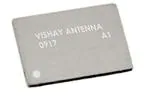
VJ 6040
Vishay Vitramon
VJ 6040 UHF Chip Antenna for Mobile Devices
FEATURES
• Small outline (10.5 mm x 15.5 mm x 1.2 mm)
• Omni-directional, linear polarization
• Complies with MBRAI standard
• Complete UHF band coverage (470 MHz to 860 MHz) up
to 1.1 GHz
• Requires a tuning circuit and ground plane for optimal
performance
The company’s products are covered by one or more of the
following:
WO2008250262 (A1), US2008303720 (A1),
US2008305750 (A1), WO2008154173 (A1).
Other patents pending.
• Standard SMT assembly
DESCRIPTION
• Compliant to RoHS directive 2002/95/EC
The VJ 6040 multi-layer ceramic chip antenna is a small
form-factor, high-performance, chip-antenna designed for
TV reception in mobile devices in the UHF band. It allows
mobile TV device manufacturers to design high quality
products that do not bear the penalty of a large external
antenna. Utilizing Vishay's unique materials and
manufacturing technologies, this product complies with the
MBRAI standard while maintaining a small outline.
Focusing on consumer applications, the antenna is designed
to be assembled onto a PC board in the standard reflow
process.
APPLICATIONS
Target customers of the VJ 6040 are mobile phone makers,
portable multimedia device makers, notebook OEMs and
ODMs, and accessory card OEMs and ODMs.
The VJ 6040 is the first of a family of products developed by
Vishay, a world leader in manufacturing of discrete and
passive components.
• 50 Ω unbalanced interface
• Operating temperature range (- 40 °C to + 85 °C)
• Reference design and evaluation boards available upon
request
• Mobile UHF TV receivers including DVB-T, DVB-H,
ISDB-T, CMMB, ATSC, and MediaFLO devices
ANTENNA PERFORMANCE
Peak gain
The antenna radiation characteristics are influenced by
several factors including ground plane dimensions and
impedance matching network.
The antenna parameters presented hereafter were
measured according to the configuration suggested by the
VJ 6040 evaluation board, utilizing its four channel active
digital tuning circuit. The evaluation board ground plane is
40 mm by 80 mm large.
Figure 1 shows peak gain over frequency throughout the
UHF band, compared with the MBRAI requirements.
0
Peak Gain (dBi)
-2
Measured
-4
Simulated
-6
Standard
-8
- 10
- 12
450
500
550
600 650 700 750
Frequency (MHz)
800
850 900
Fig. 1 - Peak gain vs. Frequency
Document Number: 45157
Revision: 15-Jun-10
For technical questions, contact: mlcc@vishay.com
www.vishay.com
1
�VJ 6040
Vishay Vitramon
VJ 6040 UHF Chip Antenna for Mobile Devices
Figure 2 displays the measured and simulated radiation efficiency of VJ 6040 over frequency.
40
35
Simulated value
Efficiency (%)
30
25
Measured value
20
15
10
5
0
460
510
560
610 660 710
Frequency (MHz)
760
810
860
Fig. 2 - Radiation Efficiency vs. Frequency
Applications that do not require full coverage of the UHF band can gain an additional two to three dBi by removing the tuning
circuit. In this case the antenna can be fixed to any 150 MHz band within the UHF range.
RADIATION PATTERN
The 3D planes of VJ 6040 are defined in figure 3.
Z
X
Y
Fig. 3 - VJ 6040 3D Plane Definition
www.vishay.com
2
For technical questions, contact: mlcc@vishay.com
Document Number: 45157
Revision: 15-Jun-10
�VJ 6040
VJ 6040 UHF Chip Antenna for Mobile Devices
Vishay Vitramon
Figure 4. displays the simulated 3D radiation pattern at 650 MHz.
Fig. 4 - Simulated Radiation Pattern
Figure 5. displays the measured radiation patterns of VJ 6040 evaluation board in the YZ plane as defined in figure 3. Zero
degrees is defined at the Z axis, stepping counter clockwise.
500 MHz - Gain (dBi) vs. Angle (°)
0
30
18 12
24
60
342
-5
36
336
330
- 15
48
54
60
- 20
- 25
66
18 12
60
354 348
342
336
-5
- 10
42
330
324
318
312
306
300
- 15
48
54
60
288
- 35
24
36
294
- 30
72
30
324
318
312
306
300
- 10
42
600 MHz - Gain (dBi) vs. Angle (°)
0
354 348
- 20
- 25
66
294
- 30
72
288
- 35
78
- 40
282
78
- 40
282
84
- 45
- 50
276
84
- 45
276
270
90
- 50
96
264
96
102
258
102
90
252
108
246
114
120
126
132
138
144
150
156
162 168
174
180
186 192
204
198
258
108
252
114
240
234
228
222
216
210
246
240
234
120
126
228
222
216
132
138
144
150
156
700 MHz - Gain (dBi) vs. Angle (°)
162 168
174 180 186 192
30
36
42
24
0
354 348
342
6
0
-5
336
- 10
- 15
- 20
48
54
60
- 25
66
78
30
330
324
318
312
306
300
24
18 12
204
210
54
- 45
- 50
330
324
318
312
306
- 20
60
282
336
- 15
48
- 40
354 348
342
- 10
42
288
60
-5
36
294
- 30
- 35
72
198
800 MHz - Gain (dBi) vs. Angle (°)
0
18 12
270
264
300
- 25
66
294
- 30
72
288
- 35
78
- 40
282
276
84
- 45
276
270
90
- 50G
96
264
96
102
258
102
84
90
108
252
114
246
240
120
126
132
138
144
150
156 162
168 174
180
198
186 192
204
234
228
222
216
210
270
264
258
108
252
114
246
120
240
234
228
222
216
126
132
138
144
150
156
162 168
174 180 186
192
198
204
210
Fig. 5 - Measured Radiation Pattern
Document Number: 45157
Revision: 15-Jun-10
For technical questions, contact: mlcc@vishay.com
www.vishay.com
3
�VJ 6040
VJ 6040 UHF Chip Antenna for Mobile Devices
Vishay Vitramon
FOOTPRINT AND MECHANICAL DIMENSIONS
The antenna footprint and mechanical dimensions are presented in figure 6. For mechanical support, it is recommended to add
one or two drops of heat curing epoxy glue. The glue dot should not overlap with any of the soldering pads. It is recommended
to apply the glue dot at the center of the antenna, as shown by the diagonal pattern. For more details see “VJ 6040 Assembly
Guidelines” section below.
0.5
0.35
3.6
1.0
0.35
0.5
3.6
4.6
1.0
`
0.35
0.35
1.0
4.65
0.5
Glue dot area
4.65
1.0
0.35
0.35
1.0
All dimensions in mm
Figure not in scale
RF feed connects here
Fig. 6 - VJ 6040 Footprint
VJ 6040 ASSEMBLY GUIDELINES
1. Mounting of antennas on a printed circuit board should be done by reflow soldering. The reflow soldering profiles are shown
below.
2. In order to provide the adequate strength between the antenna and the PCB the application of a dot of heat cured epoxy glue
in the center of the footprint of the antenna prior to the antenna's soldering to the board should be done. An example for such
glue could be Heraeus PD 860002 SA. The weight of the dot should be 5 mg to 10 mg.
300
T
(°C)
Max. temperature
250
> 215 °C: 20 s to 40 s
200
150
Min. temperature
100
Sn-Pb eutectic solder paste
50
0
30 s to 60 s
30 s to 60 s
30 s to 60 s
Time
Fig. 7 - Soldering IR Reflow with SnPb Solder
www.vishay.com
4
For technical questions, contact: mlcc@vishay.com
Document Number: 45157
Revision: 15-Jun-10
�VJ 6040
VJ 6040 UHF Chip Antenna for Mobile Devices
300
T
(°C)
250
Vishay Vitramon
10 s
260 °C
˜ 245 °C
10 s
215 °C
200
40 s
180 °C
150
130 °C
100
2 K/s
50
0
50
100
150
200
t (s) 250
Fig. 8 - Soldering Reflow with Sn Solder
300
T
(°C)
250
200
Max. temperature
Sn-Ag-Cu solder paste
150
Min. temperature
100
50
0
60 s to 120 s
60 s to 120 s
30 s to 60 s
60 s to 120 s
Time
Fig. 9 - Soldering IR Reflow with SnAgCu Solder
ORDERING INFORMATION
VISHAY MATERIAL
PACKAGING QUANTITY
VJ 6040
VJ6040M011SXISRA0
1000 pieces
Document Number: 45157
Revision: 15-Jun-10
For technical questions, contact: mlcc@vishay.com
www.vishay.com
5
�
很抱歉,暂时无法提供与“VJ6040M011SXISRA0”相匹配的价格&库存,您可以联系我们找货
免费人工找货