VLMS20.., VLMK20.., VLMO20.., VLMY20.., VLMP20..
www.vishay.com
Vishay Semiconductors
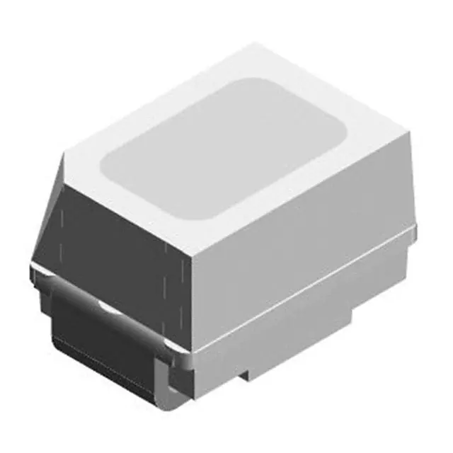
Low Current Mini SMD LED
FEATURES
• SMD LED with exceptional brightness
• Luminous intensity categorized
• Compatible with automatic placement
equipment
• Available in 8 mm tape
• Low profile package
• Non-diffused lens: excellent for coupling to
light pipes and backlighting
• Low power consumption
• IR reflow soldering according to J-STD-020
• Luminous intensity ratio in one packaging
IVmax./IVmin. ≤ 1.6
• Preconditioning according to JEDEC® level 2a
19226
DESCRIPTION
The new low current MiniLED Series have been designed in
a small white SMT package. The feature of the device is the
very small package 2.3 mm x 1.3 mm x 1.4 mm and the low
forward current. The MiniLED is an obvious solution for
small-scale, high-power products that are expected to work
reliability in an arduous environment. This is often the case
in automotive and industrial application.
• ESD-withstand voltage: up to 2 kV according to
JESD22-A114-B
• AEC-Q101 qualified
• Material categorization: for definitions of compliance
please see www.vishay.com/doc?99912
APPLICATIONS
PRODUCT GROUP AND PACKAGE DATA
•
•
•
•
unit
• Automotive: backlighting in dashboards and switches
• Telecommunication: indicator and backlighting in
telephone and fax
• Indicator and backlight for audio and video equipment
• Indicator and backlight in office equipment
• Flat backlight for LCDs, switches, and symbols
Product group: LED
Package: SMD MiniLED
Product series: low current
Angle of half intensity: ± 60°
PARTS TABLE
PART
LUMINOUS
INTENSITY
(mcd)
COLOR
at IF
(mA)
MIN. TYP. MAX.
WAVELENGTH
(nm)
FORWARD
VOLTAGE
(V)
at IF
(mA)
MIN. TYP. MAX.
at IF
(mA)
TECHNOLOGY
MIN. TYP. MAX.
VLMS2000-GS08
Super red
2.24
4.5
-
2
-
630
-
2
-
1.8
2.2
2
AllnGaP on GaAs
VLMS20H2K1-GS08
Super red
3.55
-
9
2
-
630
-
2
-
1.8
2.2
2
AllnGaP on GaAs
VLMS20H2L1-GS08
Super red
3.55
-
14
2
-
630
-
2
-
1.8
2.2
2
AllnGaP on GaAs
VLMS20J2L1-GS08
Super red
5.6
-
14
2
-
630
-
2
-
1.8
2.2
2
AllnGaP on GaAs
VLMK20J2L2-GS08 (1)
Amber
5.6
-
18
2
612
622
624
2
-
1.8
2.2
2
AllnGaP on GaAs
VLMK2000-GS08 (1)
Amber
7.1
16
-
2
612
622
624
2
-
1.8
2.2
2
AllnGaP on GaAs
VLMK20K1L2-GS08
Amber
7.1
-
18
2
612
622
624
2
-
1.8
2.2
2
AllnGaP on GaAs
VLMO20J2M1-GS08
Soft orange
5.6
-
22.4
2
598
605
611
2
-
1.8
2.2
2
AllnGaP on GaAs
AllnGaP on GaAs
VLMO20K2L2-35-GS08 (1) Soft orange
9
-
18
2
602
-
609
2
-
1.8
2.2
2
VLMY2000-GS08
Yellow
3.55
7.1
-
2
581
588
594
2
-
1.8
2.2
2
AllnGaP on GaAs
VLMY20J1L2-GS08 (1)
Yellow
4.5
-
18
2
581
588
594
2
-
1.8
2.2
2
AllnGaP on GaAs
Yellow
7.1
-
18
2
581
588
594
2
-
1.8
2.2
2
AllnGaP on GaAs
Pure green 0.56
-
2.24
2
555
-
565
2
-
1.8
2.2
2
AllnGaP on GaAs
VLMY20K1L2-GS08
VLMP20D2G1-GS08
Note
(1) Not for new design
Rev. 2.3, 20-Sep-2021
Document Number: 81339
1
For technical questions, contact: LED@vishay.com
THIS DOCUMENT IS SUBJECT TO CHANGE WITHOUT NOTICE. THE PRODUCTS DESCRIBED HEREIN AND THIS DOCUMENT
ARE SUBJECT TO SPECIFIC DISCLAIMERS, SET FORTH AT www.vishay.com/doc?91000
�VLMS20.., VLMK20.., VLMO20.., VLMY20.., VLMP20..
www.vishay.com
Vishay Semiconductors
ABSOLUTE MAXIMUM RATINGS (Tamb = 25 °C, unless otherwise specified)
VLMS20.., VLMK20.., VLMO20.., VLMY20.., VLMP20..
PARAMETER
TEST CONDITION
SYMBOL
VALUE
VR
5
V
Tamb ≤ 100 °C
IF
15
mA
tp ≤ 10 μs
IFSM
0.1
A
PV
40
mW
Reverse voltage (1)
DC forward current
Surge forward current
Power dissipation
Junction temperature
Operating temperature range
Storage temperature range
Thermal resistance junction/ambient
Mounted on PC board (pad size > 5
mm2)
UNIT
Tj
+125
°C
Tamb
-40 to +100
°C
Tstg
-40 to +100
°C
RthJA
580
K/W
Note
(2) Driving the LED in reverse direction is suitable for a short term application
OPTICAL AND ELECTRICAL CHARACTERISTICS (Tamb = 25 °C, unless otherwise specified)
VLMS20.., SUPER RED
PARAMETER
TEST CONDITION
Luminous intensity (1)
IF = 2 mA
PART
SYMBOL
MIN.
TYP.
MAX.
VLMS2000
lV
2.24
4.5
-
UNIT
mcd
VLMS20H2K1
lV
3.55
-
9
mcd
VLMS20H2L1
lV
3.55
-
14
mcd
VLMS20J2L1
lV
5.6
-
14
mcd
-
630
-
nm
nm
Dominant wavelength
IF = 2 mA
λd
Peak wavelength
IF = 2 mA
λp
-
643
-
Angle of half intensity
IF = 2 mA
ϕ
-
± 60
-
°
Forward voltage
IF = 2 mA
VF
-
1.8
2.2
V
IR = 10 μA
VR
5
-
-
V
VR = 0 V, f = 1 MHz
Cj
-
15
-
pF
Reverse voltage
Junction capacitance
Note
(1) In one packing unit I
Vmax./IVmin. ≤ 1.6
OPTICAL AND ELECTRICAL CHARACTERISTICS (Tamb = 25 °C, unless otherwise specified)
VLMK20.., AMBER
PARAMETER
TEST CONDITION
Luminous intensity (1)
IF = 2 mA
PART
SYMBOL
MIN.
VLMK20J2L2 (2)
TYP.
MAX.
UNIT
lV
VLMK2000 (2)
lV
5.6
-
18
mcd
7.1
16
-
VLMK20K1L2
mcd
lV
7.1
-
18
mcd
Dominant wavelength
IF = 2 mA
λd
612
622
624
nm
Peak wavelength
IF = 2 mA
λp
-
615
-
nm
Angle of half intensity
IF = 2 mA
ϕ
-
± 60
-
°
Forward voltage
IF = 2 mA
VF
-
1.8
2.2
V
Reverse voltage
IR = 10 μA
VR
5
-
-
V
VR = 0 V, f = 1 MHz
Cj
-
15
-
pF
Junction capacitance
Notes
(1) In one packing unit I
Vmax./IVmin. ≤ 1.6
(2) Not for new design
Rev. 2.3, 20-Sep-2021
Document Number: 81339
2
For technical questions, contact: LED@vishay.com
THIS DOCUMENT IS SUBJECT TO CHANGE WITHOUT NOTICE. THE PRODUCTS DESCRIBED HEREIN AND THIS DOCUMENT
ARE SUBJECT TO SPECIFIC DISCLAIMERS, SET FORTH AT www.vishay.com/doc?91000
�VLMS20.., VLMK20.., VLMO20.., VLMY20.., VLMP20..
www.vishay.com
Vishay Semiconductors
OPTICAL AND ELECTRICAL CHARACTERISTICS (Tamb = 25 °C, unless otherwise specified)
VLMO20.., SOFT ORANGE
PARAMETER
TEST CONDITION
Luminous intensity (1)
IF = 2 mA
Dominant wavelength
IF = 2 mA
PART
SYMBOL
MIN.
TYP.
MAX.
VLMO20J2M1
lV
5.6
-
22.4
UNIT
mcd
VLMO20K2L2-35 (2)
lV
9
-
18
mcd
VLMO20K2L2-35 (2)
λd
602
-
609
nm
VLMO20..
λd
598
605
611
nm
nm
Peak wavelength
IF = 2 mA
λp
-
610
-
Angle of half intensity
IF = 2 mA
ϕ
-
± 60
-
°
Forward voltage
IF = 2 mA
VF
-
1.8
2.2
V
IR = 10 μA
VR
5
-
-
V
VR = 0 V, f = 1 MHz
Cj
-
15
-
pF
Reverse voltage
Junction capacitance
Notes
(1) In one packing unit I
Vmax./IVmin. ≤ 1.6
(2) Not for new design
OPTICAL AND ELECTRICAL CHARACTERISTICS (Tamb = 25 °C, unless otherwise specified)
VLMY20.., YELLOW
PARAMETER
TEST CONDITION
PART
SYMBOL
MIN.
TYP.
Luminous intensity (1)
IF = 2 mA
lV
7.1
Dominant wavelength
IF = 2 mA
VLMY2000
lV
3.55
7.1
-
mcd
VLMY20J1L2 (2)
lV
4.5
-
18
mcd
λd
581
-
18
mcd
588
594
Peak wavelength
IF = 2 mA
λp
-
590
nm
-
nm
VLMY20K1L2
MAX.
UNIT
Angle of half intensity
IF = 2 mA
ϕ
-
± 60
-
°
Forward voltage
IF = 2 mA
VF
-
1.8
2.2
V
Reverse voltage
IR = 10 μA
VR
5
-
-
V
VR = 0 V, f = 1 MHz
Cj
-
15
-
pF
Junction capacitance
Notes
(1) In one packing unit I
Vmax./IVmin. ≤ 1.6
(2) Not for new design
OPTICAL AND ELECTRICAL CHARACTERISTICS (Tamb = 25 °C, unless otherwise specified)
VLMP20.., PURE GREEN
PARAMETER
Luminous intensity
TEST CONDITION
PART
IF = 2 mA
VLMP20D2G1
(1)
SYMBOL
MIN.
TYP.
MAX.
UNIT
mcd
lV
0.56
-
2.24
Dominant wavelength
IF = 2 mA
λd
555
-
565
nm
Peak wavelength
IF = 2 mA
λp
-
565
-
nm
Angle of half intensity
IF = 2 mA
ϕ
-
± 60
-
°
Forward voltage
IF = 2 mA
VF
-
1.8
2.2
V
IR = 10 μA
VR
5
-
-
V
VR = 0 V, f = 1 MHz
Cj
-
15
-
pF
Reverse voltage
Junction capacitance
Note
(1) In one packing unit I
Vmax./IVmin. ≤ 1.6
Rev. 2.3, 20-Sep-2021
Document Number: 81339
3
For technical questions, contact: LED@vishay.com
THIS DOCUMENT IS SUBJECT TO CHANGE WITHOUT NOTICE. THE PRODUCTS DESCRIBED HEREIN AND THIS DOCUMENT
ARE SUBJECT TO SPECIFIC DISCLAIMERS, SET FORTH AT www.vishay.com/doc?91000
�VLMS20.., VLMK20.., VLMO20.., VLMY20.., VLMP20..
www.vishay.com
Vishay Semiconductors
COLOR CLASSIFICATION
DOM. WAVELENGTH (nm)
GROUP
SOFT ORANGE
YELLOW
AMBER
PURE GREEN
MIN.
MAX.
MIN.
MAX.
MIN.
MAX.
MIN.
MAX.
0
-
-
-
-
-
-
555
559
1
598
601
581
584
-
-
558
561
2
600
603
583
586
-
-
560
563
3
602
605
585
588
-
-
562
565
4
604
607
587
590
-
-
-
-
5
606
609
589
592
-
-
-
-
6
608
611
591
594
-
-
-
-
7
-
-
-
-
610
613
-
-
8
-
-
-
-
612
616
-
-
9
-
-
-
-
615
620
-
-
10
-
-
-
-
619
624
-
-
Note
• Wavelengths are tested at a current pulse duration of 25 ms
LUMINOUS INTENSITY CLASSIFICATION
GROUP
LUMINOUS INTENSITY IV (mcd)
CROSSING TABLE
VISHAY
OSRAM
VLMS20H2K1
LSM67K-H2K1
STANDARD
OPTIONAL
MIN.
MAX.
D
2
0.56
0.71
VLMS20J2L1
LSM67K-J2L1
1
0.71
0.9
VLMS20H2L1
LSM67K-H2L1
2
0.9
1.12
VLMO20J2L1
LOM67K-J2L1
1
1.12
1.4
VLMO20J2M1
LOM67K-J2M1
2
1.4
1.8
VLMY20J1K2
LYM67K-J1K2
1
1.8
2.24
VLMY20K1L2
LYM67K-K1L2
2
2.24
2.8
VLMY20J1L2
LYM67K-J1L2
1
2.8
3.55
VLMP20D2G1
LPM67K-D2G1
2
3.55
4.5
VLMP20E2G1
LPM67K-E2G1
1
4.5
5.6
2
5.6
7.1
1
7.1
9
2
9
11.2
1
11.2
14
2
14
18
1
18
22.4
2
22.4
35.5
1
35.5
45
2
45
56
E
F
G
H
J
K
L
M
N
Note
• Luminous intensity is tested at a current pulse duration of 25 ms
and an accuracy of ± 11 %.
The above type numbers represent the order groups which
include only a few brightness groups. Only one group will be
shipped on each reel (there will be no mixing of two groups on
each reel).
In order to ensure availability, single brightness groups will not
be orderable.
In a similar manner for colors where wavelength groups are
measured and binned, single wavelength groups will be shipped
in any one reel.
In order to ensure availability, single wavelength groups will not
be orderable
Rev. 2.3, 20-Sep-2021
Document Number: 81339
4
For technical questions, contact: LED@vishay.com
THIS DOCUMENT IS SUBJECT TO CHANGE WITHOUT NOTICE. THE PRODUCTS DESCRIBED HEREIN AND THIS DOCUMENT
ARE SUBJECT TO SPECIFIC DISCLAIMERS, SET FORTH AT www.vishay.com/doc?91000
�VLMS20.., VLMK20.., VLMO20.., VLMY20.., VLMP20..
www.vishay.com
Vishay Semiconductors
TYPICAL CHARACTERISTICS (Tamb = 25 °C, unless otherwise specified)
40
IV rel - Relative Luminous Intensity
1.2
I F - Forward Current (mA)
35
30
25
20
15
10
5
soft orange
1.0
0.6
0.4
0.2
0
0
20
40
60
80
100
0.0
540
120
Tamb - Ambient Temperature (°C)
18557
660
700
1.2
IV rel - Relative Luminous Intensity
tp/T= 0.01
0.02
0.05
0.1
100
0.2
0.5
10
0.01
1
17557
0.1
1
10
0.4
0.2
530
550
570
590
610
λ - Wavelength (nm)
Fig. 5 - Relative Luminous Intensity vs. Wavelength
20°
1.2
40°
1.0
0.9
50°
0.8
60°
70°
ϕ - Angular Displacement
30°
0.7
0.6
18648
Fig. 2 - Forward Current vs. Pulse Length
10°
0.8
0.0
510
tp - Pulse Duration (ms)
0°
Pure green
1.0
100
80°
IV rel - RelativeLuminous Intensity
IF - Forward Current (mA)
620
λ - Wavelength (nm)
Fig. 4 - Relative Intensity vs. Wavelength
1000
IV rel - Relative Luminous Intensity
580
18266-1
Fig. 1 - Forward Current vs. Ambient Temperature
red
yellow
0.8
amber
1.0
0.8
0.6
0.4
0.2
0.0
0.6
0.4
0.2
95 10319
Fig. 3 - Relative Luminous Intensity vs. Angular Displacement
Rev. 2.3, 20-Sep-2021
570
0
16007_1
590
610
630
650
670
λ - Wavelength (nm)
Fig. 6 - Relative Luminous Intensity vs. Wavelength
Document Number: 81339
5
For technical questions, contact: LED@vishay.com
THIS DOCUMENT IS SUBJECT TO CHANGE WITHOUT NOTICE. THE PRODUCTS DESCRIBED HEREIN AND THIS DOCUMENT
ARE SUBJECT TO SPECIFIC DISCLAIMERS, SET FORTH AT www.vishay.com/doc?91000
�VLMS20.., VLMK20.., VLMO20.., VLMY20.., VLMP20..
www.vishay.com
Vishay Semiconductors
100
2.00
VF rel - Forward Voltage (V)
IF - Forward Current (mA)
yellow
10
1.5
2
2.5
3
IV rel - Relative Luminous Intensity
2.50
yellow
2.00
soft orange
1.75
red
1.50
1.25
1.00
0.75
0.50
0.25
0
- 40
- 20
0
20
40
60
80
100
Tamb - Ambient Temperature (°C)
18251-1
1.80
1.75
1.70
- 20
0
20
40
60
80
100
Tamb - Ambient Temperature (°C)
0.5
0.4
pure green
0.3
0.2
0.1
0
- 0.1
- 0.2
- 0.3
- 0.4
- 0.5
- 60 - 40 - 20
20687-1
Fig. 8 - Relative Luminous Intensity vs. Ambient Temperature
IV rel - Relative Luminous Intensity
1.85
Fig. 10 - Forward Voltage vs. Ambient Temperature
VF - Change of Forward Voltage (mV)
Fig. 7 - Forward Current vs. Forward Voltage
2.25
red
18252-1
VF - Forward Voltage (V)
95 10878
soft orange
1.90
1.65
- 40
1
1
1.95
0
20
40
60
80 100
Tamb - Ambient Temperature (°C)
Fig. 11 - Change of Forward Voltage vs. Ambient Temperature
3.0
Pure green
2.5
2.0
1.5
1.0
0.5
0.0
- 50
18616
- 25
0
25
50
75
100
Tamb - Ambient Temperature (°C)
Fig. 9 - Relative Luminous Intensity vs. Ambient Temperature
Rev. 2.3, 20-Sep-2021
Document Number: 81339
6
For technical questions, contact: LED@vishay.com
THIS DOCUMENT IS SUBJECT TO CHANGE WITHOUT NOTICE. THE PRODUCTS DESCRIBED HEREIN AND THIS DOCUMENT
ARE SUBJECT TO SPECIFIC DISCLAIMERS, SET FORTH AT www.vishay.com/doc?91000
�VLMS20.., VLMK20.., VLMO20.., VLMY20.., VLMP20..
www.vishay.com
Vishay Semiconductors
PACKAGE DIMENSIONS in millimeters
2.2 ± 0.1
1.4 ± 0.1
(1.2)
0.1 ± 0.05
0.7 ± 0.1
1.3 ± 0.1
2.05 ± 0.1
0.9 ± 0.1
0.4 ± 0.1
Not indicated tolerances ± 0.2
Cathode mark
(0.9)
Proposed pad layout
(for reference only)
0.8
(1.5)
2.8
Area not flat
1
0.8
technical drawings
according to DIN
specifications
Solder resist
Drawing-No.: 6.541-5069.01-4
Issue: 2; 24.11.14
Rev. 2.3, 20-Sep-2021
Cu.area > 5 mm2
Document Number: 81339
7
For technical questions, contact: LED@vishay.com
THIS DOCUMENT IS SUBJECT TO CHANGE WITHOUT NOTICE. THE PRODUCTS DESCRIBED HEREIN AND THIS DOCUMENT
ARE SUBJECT TO SPECIFIC DISCLAIMERS, SET FORTH AT www.vishay.com/doc?91000
�VLMS20.., VLMK20.., VLMO20.., VLMY20.., VLMP20..
www.vishay.com
Vishay Semiconductors
REEL DIMENSIONS in millimeters
16938
TAPE DIMENSIONS in millimeters
16939
LEADER AND TRAILER DIMENSIONS in millimeters
Trailer
no devices
Leader
devices
no devices
End
Start
min. 200
min. 400
96 11818
GS08 = 3000 pcs
Rev. 2.3, 20-Sep-2021
Document Number: 81339
8
For technical questions, contact: LED@vishay.com
THIS DOCUMENT IS SUBJECT TO CHANGE WITHOUT NOTICE. THE PRODUCTS DESCRIBED HEREIN AND THIS DOCUMENT
ARE SUBJECT TO SPECIFIC DISCLAIMERS, SET FORTH AT www.vishay.com/doc?91000
�VLMS20.., VLMK20.., VLMO20.., VLMY20.., VLMP20..
www.vishay.com
Vishay Semiconductors
COVER TAPE PEEL STRENGTH
LABEL
According to DIN EN 60286-3
Standard bar code labels for finished goods
0.1 N to 1.3 N
The standard bar code labels are product labels and used
for identification of goods. The finished goods are packed in
final packing area. The standard packing units are labeled
with standard bar code labels before transported as finished
goods to warehouses. The labels are on each packing unit
and contain Vishay Semiconductor GmbH specific data.
300 mm/min ± 10 mm/min
165° to 180° peel angle
VISHAY SEMICONDUCTOR GmbH STANDARD BAR CODE PRODUCT LABEL (finished goods)
PLAIN WRITING
ABBREVIATION
LENGTH
Item-description
-
18
Item-number
INO
8
Selection-code
SEL
3
LOT-/serial-number
Data-code
BATCH
10
COD
3 (YWW)
Plant-code
PTC
2
Quantity
QTY
8
Accepted by:
ACC
-
Packed by:
PCK
-
MIXED CODE
-
xxxxxxx+
Company Logo
TYPE
LENGTH
Item-number
N
8
Plant-code
N
2
Sequence-number
X
3
Quantity
N
8
Total length
-
21
Mixed code indicator
Origin
LONG BAR CODE TOP
SHORT BAR CODE BOTTOM
TYPE
LENGTH
Selection-code
X
3
Data-code
N
3
Batch-number
X
10
Filter
-
1
Total length
-
17
SOLDERING PROFILE
IR Reflow Soldering Profile for lead (Pb)-free soldering
Preconditioning acc. to JEDEC Level 2a
300
max. 260 °C
245 °C
255
255°C°C
240 °C
217 °C
250
T [°C]
200
max. 30 s
150
max. 100 s
max. 120 s
100
max. Ramp Down 6 °C/s
max. Ramp Up 3 °C/s
50
0
0
19470-3
50
100
150
200
250
300
t [s]
max. 2 cycles allowed
Fig. 12 - Vishay Lead (Pb)-free Reflow Soldering Profile
(according to J-STD-020)
Rev. 2.3, 20-Sep-2021
Document Number: 81339
9
For technical questions, contact: LED@vishay.com
THIS DOCUMENT IS SUBJECT TO CHANGE WITHOUT NOTICE. THE PRODUCTS DESCRIBED HEREIN AND THIS DOCUMENT
ARE SUBJECT TO SPECIFIC DISCLAIMERS, SET FORTH AT www.vishay.com/doc?91000
�VLMS20.., VLMK20.., VLMO20.., VLMY20.., VLMP20..
www.vishay.com
Vishay Semiconductors
BAR CODE PRODUCT LABEL (example)
RECOMMENDED METHOF OF STORAGE
Dry box storage is recommended as soon as the aluminum
bag has been opened to prevent moisture absorption. The
following conditions should be observed, if dry boxes are
not available:
106
A
H
VISHAY
• Storage temperature 10 °C to 30 °C
37
• Storage humidity ≤ 60 % RH max.
After more than 672 h under these conditions moisture
content will be too high for reflow soldering.
B
C
D
E
F
20146
G
A. Type of component
B. Manufacturing plant
C. SEL - selection code (bin):
e.g.: J2 = code for luminous intensity group
4 = code for color group
In case of moisture absorption, the devices will recover to
the former condition by drying under the following condition:
192 h at 40 °C + 5 °C / - 0 °C and < 5 % RH (dry air /
nitrogen) or
96 h at 60 °C + 5 °C and < 5 % RH for all device containers
or
24 h at 100 °C + 5 °C not suitable for reel or tubes.
An EIA JEDEC standard JESD22-A112 level 2a label is
included on all dry bags.
D. Date code year / week
E. Day code (e.g. 4: Thursday)
L E V E L
CAUTION
F. Batch no.
This bag contains
MOISTURE –SENSITIVE DEVICES
G. Total quantity
H. Company code
2a
1. Shelf life in sealed bag 12 months at


 工商网监
湘ICP备2023018690号
工商网监
湘ICP备2023018690号
