VLMR51Z1AA, VLMK51Z1AA, VLMY51Z1AA
www.vishay.com
Vishay Semiconductors
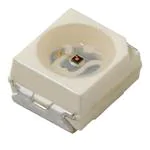
Power SMD LED PLCC-2 Plus
FEATURES
• High efficient AlInGaP technology
• Compact package outline 3.5 mm x 3.5 mm x
1.2 mm
• Angle of half intensity ϕ = ± 60°
• Luminous intensity and color categorized per
packing unit
• Luminous intensity ratio per packing unit
φmin./φmax. < 1.6
• ESD-withstand voltage: Up to 2 kV (HBM)
according to JESD22-A114-B
• Preconditioning according to JEDEC® level 2a
• Compatible with IR-reflow soldering profiles
according to J-STD-020
• AEC-Q101 qualified
• Material categorization: For definitions of compliance
please see www.vishay.com/doc?99912
22068
DESCRIPTION
The VLMR51.., VLMK51.., and VLMY51.. LED series in
PLCC2 plus package are an advanced product in terms of
high luminous flux and low thermal resistance.
In combination with the small package outline (3.5 mm x
3.5 mm x 1.2 mm) the PLCC2 plus is an ideal choice for
backlighting, signage, exterior and interior automotive
lighting as well as decorative lighting.
APPLICATIONS
PRODUCT GROUP AND PACKAGE DATA
•
•
•
•
• Interior and exterior automotive lighting: Dashboard,
brake lights, turn lights, backlighting
• Signal and symbol luminaire
• Decorative lighting
• Architectural lighting
• Backlighting: LCDs, switches, keys, illuminated
advertising
• Marker lights
• Traffic lights
Product group: LED
Package: SMD PLCC-2 plus
Product series: power
Angle of half intensity: ± 60°
PARTS TABLE
PART
LUMINOUS
INTENSITY
(mcd)
COLOR
at IF
(mA)
WAVELENGTH
(nm)
MIN.
FORWARD
VOLTAGE
(V)
at IF
(mA)
TYP. MAX.
MIN.
at IF
(mA)
TECHNOLOGY
AlInGaP on Si
MIN.
TYP. MAX.
VLMR51Z1AA-GS08
Red
4500
7100
9000
140
620
-
630
140
1.9
TYP. MAX.
2.2
2.65
140
VLMK51Z1AA-GS08
Amber
4500
7100
9000
140
610
-
621
140
1.9
2.2
2.65
140
AlInGaP on Si
VLMY51Z1AA-GS08
Yellow
4500
7100
9000
140
585
-
594
140
1.9
2.2
2.65
140
AlInGaP on Si
ABSOLUTE MAXIMUM RATINGS (Tamb = 25 °C, unless otherwise specified)
VLMR51.., VLMK51.., VLMY51..
PARAMETER
Reverse voltage
TEST CONDITION
SYMBOL
VALUE
IR = 10 μA
VR
12
V
IF
200
mA
IFSM
1000
mA
PV
530
mW
DC forward current
Surge forward current
tp ≤ 10 μs
Power dissipation
Junction temperature
UNIT
Tj
125
°C
Operating temperature range
Tamb
- 40 to + 110
°C
Storage temperature range
Tstg
- 40 to + 110
°C
RthJS
50
K/W
RthJA
100
K/W
Thermal resistance junction/solder point
Thermal resistance junction/ambient
Rev. 1.4, 03-Sep-13
Mounted on PCB, total Cu area > 900 mm2
Document Number: 83419
1
For technical questions, contact: LED@vishay.com
THIS DOCUMENT IS SUBJECT TO CHANGE WITHOUT NOTICE. THE PRODUCTS DESCRIBED HEREIN AND THIS DOCUMENT
ARE SUBJECT TO SPECIFIC DISCLAIMERS, SET FORTH AT www.vishay.com/doc?91000
�VLMR51Z1AA, VLMK51Z1AA, VLMY51Z1AA
www.vishay.com
Vishay Semiconductors
OPTICAL AND ELECTRICAL CHARACTERISTICS (Tamb = 25 °C, unless otherwise specified)
VLMR51.., RED
PARAMETER
TEST CONDITION
PART
SYMBOL
MIN.
TYP.
MAX.
UNIT
Luminous intensity
IF = 140 mA
VLMR51Z1AA
IV
4500
7100
9000
mcd
Luminous flux
IF = 140 mA
VLMR51Z1AA
φV
-
20
-
lm
Dominant wavelength
IF = 140 mA
λd
620
-
630
nm
Angle of half intensity
IF = 140 mA
ϕ
-
± 60
-
deg
Forward voltage
IF = 140 mA
VF
1.9
2.2
2.65
V
Temperature coefficient IV
IF = 140 mA, 0 °C ≤ T ≤ 100 °C
TCIV
-
- 26.8
-
mcd/K
Temperature coefficient VF
IF = 140 mA, 0 °C ≤ T ≤ 100 °C
TCV
-
- 3.5
-
mV/K
Temperature coefficient λd
IF = 140 mA, 0 °C ≤ T ≤ 100 °C
TCλd
-
0.06
-
nm/K
Note
• Forward voltages are tested using a current pulse of 1 ms and has an accuracy of ± 0.1 V
OPTICAL AND ELECTRICAL CHARACTERISTICS (Tamb = 25 °C, unless otherwise specified)
VLMK51.., AMBER
PARAMETER
TEST CONDITION
PART
SYMBOL
MIN.
TYP.
MAX.
UNIT
Luminous intensity
IF = 140 mA
VLMK51Z1AA
IV
4500
7100
9000
mcd
Luminous flux
IF = 140 mA
VLMK51Z1AA
φV
-
20
-
lm
Dominant wavelength
IF = 140 mA
λd
610
-
621
nm
Angle of half intensity
IF = 140 mA
ϕ
-
± 60
-
deg
Forward voltage
IF = 140 mA
VF
1.9
2.2
2.65
V
Temperature coefficient IV
IF = 140 mA, 0 °C ≤ T ≤ 100 °C
TCIV
-
- 35.3
-
mcd/K
Temperature coefficient VF
IF = 140 mA, 0 °C ≤ T ≤ 100 °C
TCV
-
- 2.9
-
mV/K
Temperature coefficient λd
IF = 140 mA, 0 °C ≤ T ≤ 100 °C
TCλd
-
0.07
-
nm/K
Note
• Forward voltages are tested using a current pulse of 1 ms and has an accuracy of ± 0.1 V
OPTICAL AND ELECTRICAL CHARACTERISTICS (Tamb = 25 °C, unless otherwise specified)
VLMY51.., YELLOW
PARAMETER
TEST CONDITION
PART
SYMBOL
MIN.
TYP.
MAX.
UNIT
Luminous intensity
IF = 140 mA
VLMY51Z1AA
IV
4500
7100
9000
mcd
Luminous flux
IF = 140 mA
VLMY51Z1AA
φV
-
20
-
lm
Dominant wavelength
IF = 140 mA
λd
585
-
594
nm
Angle of half intensity
IF = 140 mA
ϕ
-
± 60
-
deg
IF = 140 mA
VF
1.9
2.2
2.65
V
Temperature coefficient IV
Forward voltage
IF = 140 mA, 0 °C ≤ T ≤ 100 °C
TCIV
-
- 55.5
-
mcd/K
Temperature coefficient VF
IF = 140 mA, 0 °C ≤ T ≤ 100 °C
TCV
-
- 2.9
-
mV/K
Temperature coefficient λd
IF = 140 mA, 0 °C ≤ T ≤ 100 °C
TCλd
-
0.09
-
nm/K
Note
• Forward voltages are tested using a current pulse of 1 ms and has an accuracy of ± 0.1 V
Rev. 1.4, 03-Sep-13
Document Number: 83419
2
For technical questions, contact: LED@vishay.com
THIS DOCUMENT IS SUBJECT TO CHANGE WITHOUT NOTICE. THE PRODUCTS DESCRIBED HEREIN AND THIS DOCUMENT
ARE SUBJECT TO SPECIFIC DISCLAIMERS, SET FORTH AT www.vishay.com/doc?91000
�VLMR51Z1AA, VLMK51Z1AA, VLMY51Z1AA
www.vishay.com
Vishay Semiconductors
LUMINOUS INTENSITY CLASSIFICATION
GROUP
COLOR CLASSIFICATION
LIGHT INTENSITY (mcd)
DOM. WAVELENGTH (nm)
STANDARD
MIN.
MAX.
Z1
4500
5600
MIN.
MAX.
MIN.
Z2
5600
7150
W
610
615
-
-
AA
7150
9000
X
615
621
585
588
Y
-
-
588
591
Z
-
-
591
594
Note
• Luminous flux is tested at a current pulse duration of 25 ms and
an accuracy of ± 11 %.
The above type numbers represent the order groups which
include only a few brightness groups. Only one group will be
shipped on each reel (there will be no mixing of two groups on
each reel).
In order to ensure availability, single brightness groups will not
be orderable.
In a similar manner for colors where wavelength groups are
measured and binned, single wavelength groups will be shipped
on any one reel.
In order to ensure availability, single wavelength groups will not
be orderable.
GROUP
AMBER
YELLOW
MAX.
Note
• Wavelengths are tested at a current pulse duration of 25 ms and
an accuracy of ± 1 nm.
1.4
250
IV rel - Luminous Intensity
IFmax. - Maximum Forward Current (mA)
TYPICAL CHARACTERISTICS (Tamb = 25 °C, unless otherwise specified)
200
150
100
50
1.0
0.8
0.6
0.4
0.2
0
0
0
20
40
60
80
100
0
120
22071
Tamb - Ambient Temperature (°C)
22069
Fig. 1 - Forward Current vs. Ambient Temperature
50
100
150
200
IF - Forward Current (mA)
Fig. 3 - Relative Luminous Intensity vs. Forward Current
2.5
250
VF - Forward Voltage (V)
IFmax. - Maximum Forward Current (mA)
1.2
200
150
100
50
2.0
1.5
1.0
0.5
0
0
0
22070
20
40
60
80
100
TSP - Solder Point Temperature (°C)
Fig. 2 - Maximum Forward Current vs. Solder Point Temperature
Rev. 1.4, 03-Sep-13
0
120
22072
50
100
150
200
IF - Forward Current (mA)
Fig. 4 - Relative Forward Voltage vs. Forward Current
Document Number: 83419
3
For technical questions, contact: LED@vishay.com
THIS DOCUMENT IS SUBJECT TO CHANGE WITHOUT NOTICE. THE PRODUCTS DESCRIBED HEREIN AND THIS DOCUMENT
ARE SUBJECT TO SPECIFIC DISCLAIMERS, SET FORTH AT www.vishay.com/doc?91000
�VLMR51Z1AA, VLMK51Z1AA, VLMY51Z1AA
Vishay Semiconductors
I v rel - Relative Luminous Intensity
0°
1000
10°
20°
30°
40°
1.0
0.9
50°
0.8
60°
70°
0.7
ϕ - Angular Displacement
IFmax. - Maximum Forward Current (mA)
www.vishay.com
80°
100
1
10
100
Duty Ratio (%); Ta = 25 °C, tp < 10 µs
Fig. 5 - Forward Current vs. Duty Ratio
0.6
0.4
0.2
0
95 10043
Fig. 7 - Relative Luminous Intensity vs. Angular Displacement
Irel - Relative Intensity
1.2
amber
1.0
yellow
red
0.8
0.6
0.4
0.2
0.0
540 560 580 600 620 640 660 680
22074
λ - Wavelenght (nm)
Fig. 6 - Relative Intensity vs. Wavelength
Rev. 1.4, 03-Sep-13
Document Number: 83419
4
For technical questions, contact: LED@vishay.com
THIS DOCUMENT IS SUBJECT TO CHANGE WITHOUT NOTICE. THE PRODUCTS DESCRIBED HEREIN AND THIS DOCUMENT
ARE SUBJECT TO SPECIFIC DISCLAIMERS, SET FORTH AT www.vishay.com/doc?91000
�VLMR51Z1AA, VLMK51Z1AA, VLMY51Z1AA
www.vishay.com
Vishay Semiconductors
Ø 180
Ø 62.5 - 2.5
REEL DIMENSIONS in millimeters
Ø 13 ± 0.2
12.4 + 2
Label area with depression
(Measured at outer edge)
18.4
(max., Measured at hub)
technical drawings
according to DIN
specifications
Not indicated tolerances ± 0.5
GS08 = 1000 pcs
Material: black static dissipative
Drawing-No.: 9.800-5104.01-4
Issue: 2; 19.03.10
22067
Rev. 1.4, 03-Sep-13
Document Number: 83419
5
For technical questions, contact: LED@vishay.com
THIS DOCUMENT IS SUBJECT TO CHANGE WITHOUT NOTICE. THE PRODUCTS DESCRIBED HEREIN AND THIS DOCUMENT
ARE SUBJECT TO SPECIFIC DISCLAIMERS, SET FORTH AT www.vishay.com/doc?91000
�VLMR51Z1AA, VLMK51Z1AA, VLMY51Z1AA
www.vishay.com
Vishay Semiconductors
TAPING AND ORIENTATION DIMENSIONS in millimeters
Reels come in quantity of 1000 units.
3.75 ± 0.1
2.2 ± 0.1
3.75 ± 0.1
Package marking
+ 0.3
12 - 0.1
2 ± 0.05
5.5 ± 0.05
4 ± 0.1
1.75 ± 0.1
Ø 1.5 + 0.1
0.279 ± 0.02
Ø 1.5 + 0.25
8 ± 0.1
200 mm min. for Ø 180 reel
Trailer
480 mm min. for Ø 180 reel
Component
Leader
User feed direction
Drawing-No.: 9.700-5348.01-4
Issue: 1; 01.03.10
technical drawings
according to DIN
specifications
22066
Rev. 1.4, 03-Sep-13
Document Number: 83419
6
For technical questions, contact: LED@vishay.com
THIS DOCUMENT IS SUBJECT TO CHANGE WITHOUT NOTICE. THE PRODUCTS DESCRIBED HEREIN AND THIS DOCUMENT
ARE SUBJECT TO SPECIFIC DISCLAIMERS, SET FORTH AT www.vishay.com/doc?91000
�VLMR51Z1AA, VLMK51Z1AA, VLMY51Z1AA
www.vishay.com
Vishay Semiconductors
RECOMMENDED PAD DESIGN DIMENSIONS in millimeters
2.6
0.05
Package mark
3.7 ± 0.2
Ø 2.6
1.5
3.1
3.5 ± 0.2
C
A
0.5
3.5 ± 0.2
0.7
Recommended solder pad
Additional area covered by solder resist
1.2 ± 0.2
for improved heat dissipation.
technical drawings
according to DIN
specifications
0.5
4.5
3.4
9.4
1.4
2.8
10
Drawing-No.: 6.541-5084.01-4
Issue: 1 ; 13.04.10
22103
Rev. 1.4, 03-Sep-13
Document Number: 83419
7
For technical questions, contact: LED@vishay.com
THIS DOCUMENT IS SUBJECT TO CHANGE WITHOUT NOTICE. THE PRODUCTS DESCRIBED HEREIN AND THIS DOCUMENT
ARE SUBJECT TO SPECIFIC DISCLAIMERS, SET FORTH AT www.vishay.com/doc?91000
�VLMR51Z1AA, VLMK51Z1AA, VLMY51Z1AA
www.vishay.com
Vishay Semiconductors
FINAL PACKING
SOLDERING PROFILE
The sealed reel is packed into a cardboard box. A secondary
cardboard box is used for shipping purposes.
IR Reflow Soldering Profile for lead (Pb)-free soldering
Preconditioning acc. to JEDEC Level 2a
300
max. 260 °C
245 °C
255
255°C°C
240 °C
217 °C
250
Dry box storage is recommended as soon as the aluminum
bag has been opened to prevent moisture absorption. The
following conditions should be observed, if dry boxes are
not available:
T [°C]
200
max. 30 s
150
max. 100 s
max. 120 s
RECOMMENDED METHOD OF STORAGE
100
• Storage temperature 10 °C to 30 °C
max. Ramp Down 6 °C/s
max. Ramp Up 3 °C/s
50
• Storage humidity ≤ 60 % RH max.
0
0
50
100
150
200
250
300
t [s]
19470-3
max. 2 cycles allowed
Fig. 8 - Vishay Lead (Pb)-free Reflow Soldering Profile
(acc. to J-STD-020)
BAR CODE PRODUCT LABEL (example)
106
A
After more than 672 h under these conditions moisture
content will be too high for reflow soldering.
In case of moisture absorption, the devices will recover to
the former condition by drying under the following condition:
192 h at 40 °C + 5 °C/- 0 °C and < 5 % RH (dry air/nitrogen)
or
96 h at 60 °C + 5 °C and < 5 % RH for all device containers
or
24 h at 100 °C + 5 °C not suitable for reel or tubes.
An EIA JEDEC standard JESD22-A112 level 2a label is
included on all dry bags.
H
37
L E V E L
CAUTION
This bag contains
MOISTURE –SENSITIVE DEVICES
B
C
D
E
F
G
19795
A) Type of component
B) Manufacturing plant
C) SEL - selection code (bin):
e.g.: V1 = code for luminous intensity group
5L = code for chrom. coordinate group
D) Date code year/week
E) Day code (e.g. 1: Monday)
F) Batch no.
G) Total quantity
H) Company code
2a
1. Shelf life in sealed bag 12 months at