VY1 Series
www.vishay.com
Vishay BCcomponents
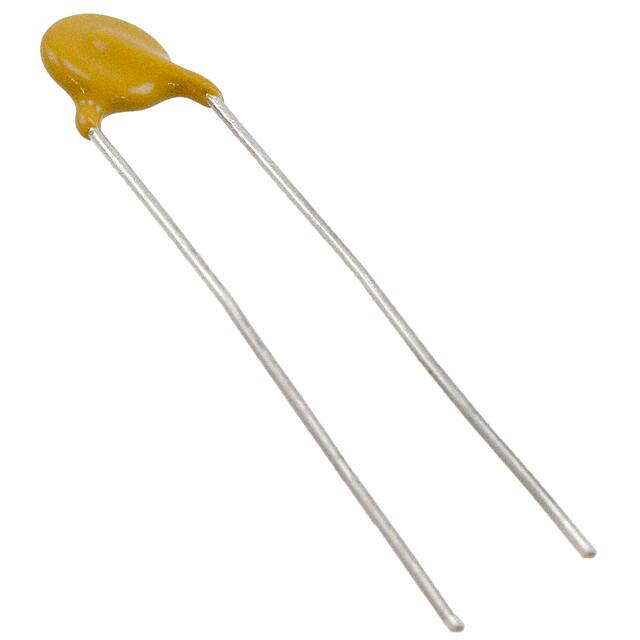
EMI Suppression Safety Capacitor, Ceramic Disc,
Class X1, 760 VAC, Class Y1, 500 VAC
FEATURES
•
•
•
•
•
Complying with IEC 60384-14
High reliability
Vertical (inline) kinked or straight leads
Singlelayer AC disc safety capacitors
Material categorization:
for definitions of compliance please see
www.vishay.com/doc?99912
APPLICATIONS
LINKS TO ADDITIONAL RESOURCES
3D 3D
3D Models
•
•
•
•
•
X1, Y1 according to IEC 60384-14
Line-to-line filtering (Class X)
Line-to-ground filtering (Class Y)
Primary and secondary coupling (SMPS)
EMI / RFI suppression and filtering
DESIGN
Models
QUICK REFERENCE DATA
DESCRIPTION
Ceramic Class
VALUE
1
Ceramic Dielectric
U2J
Voltage (VAC)
Min. Capacitance (pF)
Max. Capacitance (pF)
Mounting
500
U2J
760
10
22
2
Y5S, Y5U, Y5S, Y5U,
Y5V
Y5V
500
760
33
4700
Radial
OPERATING TEMPERATURE RANGE
-40 °C to +125 °C
TEMPERATURE CHARACTERISTICS
Class 1: N750 (U2J)
Class 2: Y5S, Y5U, Y5V
SECTIONAL SPECIFICATIONS
Climatic category (according to EN 60058-1)
Class 1 and class 2: 40/125/21
COATING
According to UL 94 V-0
Epoxy resin, isolating, flame retardant
Halogen-free available
Reinforced insulation
APPROVALS
IEC 60384-14
UL 60384-14
DIN EN 60384-14
CSA E60384-1:03, CSA E60384-14:09
CQC11-471112-2009
The capacitor consists of a ceramic disc which is silver
plated on both sides. Connection leads are made of tinned
copper clad steel having a diameter of 0.6 mm.
The capacitors may be supplied with vertical (inline) kinked
leads having a lead spacing of 10.0 mm, or 12.5 mm.
Encapsulation is made of flame retardant epoxy resin
in accordance with UL 94 V-0.
CAPACITANCE RANGE
10 pF to 4700 pF
RATED VOLTAGE UR
IEC 60384-14:
(X1): 760 VAC, 50 Hz
(Y1): 500 VAC, 50 Hz
1500 VDC
TEST VOLTAGE
Component test (100 %):
4000 VAC, 50 Hz, 2 s
Random sampling test (destructive test):
4000 VAC, 50 Hz, 60 s
Voltage proof of coating (destructive test):
4000 VAC, 50 Hz, 60 s
INSULATION RESISTANCE
≥ 10 000 MΩ
CAPACITANCE TOLERANCE
± 20 % (code M); ± 10 % (code K)
DISSIPATION FACTOR
Class 1: max. 0.5 % (1 MHz)
Class 2: max. 2.5 % (1 kHz)
PACKAGING
Bulk, tape and reel, taped ammopack
Revision: 16-Sep-2021
Document Number: 28537
1
For technical questions, contact: cdc@vishay.com
THIS DOCUMENT IS SUBJECT TO CHANGE WITHOUT NOTICE. THE PRODUCTS DESCRIBED HEREIN AND THIS DOCUMENT
ARE SUBJECT TO SPECIFIC DISCLAIMERS, SET FORTH AT www.vishay.com/doc?91000
�VY1 Series
www.vishay.com
Vishay BCcomponents
DIMENSIONS in millimeters
F
e = 3.0 max.
SH = 4.0 max.
Ø 0.6 ± 0.05
Dmax.
Tmax.
L = 30.0 ± 5.0
Capacitors with 10.0 mm or 12.5 mm lead spacing
TECHNICAL DATA
CAPACITANCE
C (pF)
CAPACITANCE
TOLERANCE
(%)
BODY
DIAMETER
Dmax. (mm)
BODY
THICKNESS
Tmax. (mm)
LEAD SPACING
F (mm) ± 1 mm
± 10
8.0
5.0
10.0 or 12.5
PART NUMBER
MISSING DIGITS SEE
ORDERING CODE BELOW
U2J (N750)
10
15
VY1100K31U2JQ6###
22
VY1150K31U2JQ6###
VY1220K31U2JQ6###
Y5S (2C3)
33
VY1330K31Y5SQ6###
47
VY1470K31Y5SQ6###
68
VY1680K31Y5SQ6###
100
± 10
8.0
5.0
10.0 or 12.5
VY1101K31Y5SQ6###
150
VY1151K31Y5SQ6###
220
VY1221K31Y5SQ6###
330
VY1331K31Y5SQ6###
Y5U (2E3)
470
1000
1500
2200
VY1471#31Y5UQ6###
8.0
680
VY1681#31Y5UQ6###
9.0
± 20 (1)
10.5
12.0
VY1102#35Y5UQ6###
5.0
10.0 or 12.5
VY1152#41Y5UQ6###
VY1222#47Y5UQ6###
3300
15.0
VY1332#59Y5UQ6###
3900
15.5
VY1392#61Y5UQ6###
4700
16.0
VY1472#63Y5UQ6###
Y5V (2F3) MINI SIZE SERIES
1000
7.5
VY1102M29Y5VQ6###
1500
8.5
VY1152M33Y5VQ6###
2200
3300
± 20
9.5
11.0
5.5
10.0 or 12.5
VY1222M37Y5VQ6###
VY1332M43Y5VQ6###
3900
12.0
VY1392M47Y5VQ6###
4700
13.0
VY1472M51Y5VQ6###
Notes
• Straight leads available on request
• Coating extension DR valid for straight leads only
(1) ± 10 % available on request
Revision: 16-Sep-2021
Document Number: 28537
2
For technical questions, contact: cdc@vishay.com
THIS DOCUMENT IS SUBJECT TO CHANGE WITHOUT NOTICE. THE PRODUCTS DESCRIBED HEREIN AND THIS DOCUMENT
ARE SUBJECT TO SPECIFIC DISCLAIMERS, SET FORTH AT www.vishay.com/doc?91000
�VY1 Series
www.vishay.com
Vishay BCcomponents
ORDERING CODE
#
7th digit
Capacitance tolerance
± 10 % = K, ± 20 % = M
###
15th to 17th digit
Lead configuration
Available configurations see below
Example
VY1
101
Series
Capacitance
value
K
31
Tolerance Size code
code
Y5S
Q
Temperature
coefficient
Rated
voltage
6
T
Lead wire Packaging /
diameter lead length
Q=
X1/Y1
500 V (AC)
3 = bulk
T = tape
and reel
U=
ammopack
V
0
Lead
style
Lead
spacing
L=
straight
V = inline
kinked
0 = 10.0
X = 12.5
PACKAGING
SIZE CODE
BODY DIAMETER
Dmax. (mm)
31 to 47
51 to 63
12.0
16.0
PACKAGING QUANTITIES
REEL
500
500
BULK
1000
500
AMMO
750
750
Note
• The capacitors are supplied in bulk packaging (cardboard boxes), in tape on reel or in ammopack
STRAIGHT LEADS
Tmax.
Dmax.
coating
extension
e
3.0 max.
30 mm to 3.0 mm (ΔR)
F
d = 0.6 mm
P
D
P2
ΔP
ΔP
Δh
T
Δh
H1
F
Ød
W2
L
H0
W1
W0 W
L1
P0
P1
F
A
D0
t1
t
detail A
The sprocket hole pitch (P0) is 12.7 mm for lead spacing 10.0 mm and 12.5 mm
Revision: 16-Sep-2021
Document Number: 28537
3
For technical questions, contact: cdc@vishay.com
THIS DOCUMENT IS SUBJECT TO CHANGE WITHOUT NOTICE. THE PRODUCTS DESCRIBED HEREIN AND THIS DOCUMENT
ARE SUBJECT TO SPECIFIC DISCLAIMERS, SET FORTH AT www.vishay.com/doc?91000
�VY1 Series
www.vishay.com
Vishay BCcomponents
DIMENSIONS OF TAPE
DIMENSIONS
(mm)
SYMBOL
PARAMETER
D (1)
Body diameter
16.0 max.
d
Lead diameter
0.6 ± 0.05
P
Pitch of component
25.4 ± 1
P0 (2)
Pitch of sprocket hole
12.7 ± 0.3
P1 (3)
Distance, hole center to lead
7.7 or 6.4 ± 1.0
P2 (3)
Distance, hole to center of component
12.7 ± 1.5
F
Lead spacing
10.0 or 12.5 + 0.6/- 0.4
± 1.0 max.
Δh
Average deviation across tape
ΔP
Average deviation in direction of reeling
± 1.0 max.
W
Carrier tape width
18.0 + 1/- 0.5
W0
Hold-down tape width
5.0 min.
W1
Position of sprocket hole
9.0 + 0.75/- 0.5
W2
Distance of hold-down tape
3.0 max.
H1
Maximum component height
40.0
H0
Height to seating plane (for kinked leads)
16.0 ± 0.5
H0
Height to seating plane (for straight leads)
20.0 ± 0.5
L
Length of cut leads
11.0 max.
L1
Length of lead protrusion
1.0 max.
D0
Diameter of sprocket hole
4.0 ± 0.2
t
Total tape thickness
0.9 max.
t1
Total tape thickness with lead wire
t+d
Notes
(1) See “Technical Data” table
(2) Cumulative pitch error: ± 1 mm/20 pitches
(3) Obliquity maximum 3°
REEL AND TAPE DATA in millimeters
51 max.
355.6 ± 2.0
330
28 ± 1.5
8.0
45 max.
360
55
Reel with capacitors on tape
Revision: 16-Sep-2021
Ammopack with capacitors on tape
Document Number: 28537
4
For technical questions, contact: cdc@vishay.com
THIS DOCUMENT IS SUBJECT TO CHANGE WITHOUT NOTICE. THE PRODUCTS DESCRIBED HEREIN AND THIS DOCUMENT
ARE SUBJECT TO SPECIFIC DISCLAIMERS, SET FORTH AT www.vishay.com/doc?91000
�VY1 Series
www.vishay.com
Vishay BCcomponents
APPROVALS
IEC 60384-14 - Safety tests
This approval together with CB test certificate substitutes all national approvals.
CB Certificate
Y1-capacitor: CB test certificate:
US-26561-UL
10 pF to 4.7 nF
500 VAC
X1-capacitor: CB test certificate:
US-26561-UL
10 pF to 4.7 nF
760 VAC
VDE
Y1-capacitor: VDE marks approval:
40012673
10 pF to 4.7 nF
500 VAC
X1-capacitor: VDE marks approval:
40012673
10 pF to 4.7 nF
760 VAC
DIN EN 60384-14 VDE 0565-1-1:2006-04 - Safety tests
Underwriters Laboratories Inc./Canadian Standards Association
Y1-capacitor: CSA test certificate:
E183844
10 pF to 4.7 nF
500 VAC
X1-capacitor: CSA test certificate:
E183844
10 pF to 4.7 nF
760 VAC
UL 60384-14, CSA E60384-1:03, CSA E60384-14:09
Fixed capacitors for electromagnetic interference suppression and connection to the supply mains.
CQC
Y1-capacitor: CQC test certificate:
CQC05001015032
10 pF to 4.7 nF
500 VAC
X1-capacitor: CQC test certificate:
CQC05001015032
10 pF to 4.7 nF
760 VAC
MARKING
Sample
(2 sides)
10
VY1 472M
Y1 500~
X1 760~
xxxx
250~
4 digit date code
(year/week; add suffix “V” for mini size series)
Revision: 16-Sep-2021
Document Number: 28537
5
For technical questions, contact: cdc@vishay.com
THIS DOCUMENT IS SUBJECT TO CHANGE WITHOUT NOTICE. THE PRODUCTS DESCRIBED HEREIN AND THIS DOCUMENT
ARE SUBJECT TO SPECIFIC DISCLAIMERS, SET FORTH AT www.vishay.com/doc?91000
�VY1 Series
www.vishay.com
Vishay BCcomponents
PERFORMANCE
TEST
Visual and
mechanical
inspection
Capacitance
(C)
Dissipation
factor (DF)
TEST CONDITION
Optical inspection, dimensions measured with caliper
25 °C ± 3 °C , relative humidity (RH) ≤ 75 %,
1.0 VRMS ± 0.2 VRMS at 1 kHz for Y5U and Y5S, and 1 MHz for U2J
TEST LIMITS
No visible damage, marking legible
Capacitance within specified tolerance
DF ≤ 0.3 % for U2J and
DF ≤ 2.5 % for Y5S and Y5U
Insulation
resistance (IR)
Measured within 60 s ± 5 s after charging at 500 VDC
10 000 MΩ min.
Dielectric
strength
4000 VAC at 50 Hz/60 Hz for 1 min, 50 mA max.
No failure
Temperature
characteristic
RH ≤ 75 %, 1.0 VRMS ± 0.2 VRMS at 1 kHz for Y5U and Y5S,
and 1 MHz for U2J
U2J: -750 ppm ± 120 ppm
Y5S: ± 22 %
Y5U: +22 %/-56 %
Impulse
voltage
3 pulses of 8 kV
No failure
Life test
Humidity test
1000 h at 125 °C ± 2 °C, 850 VAC/50 Hz;
once every hour 1000 VAC for 0.1 s
500 h at 500 VAC, 50 Hz and 500 h unloaded
40 °C, RH = 90 % to 95%
External appearance: no visible damage
ΔC/C ≤ ± 15 %
DF ≤ 0.5 % for U2J and ≤ 5 % for Y5S and Y5U
IR ≥ 3000 MΩ
Dielectric strength: no failure
External appearance: no visible damage
ΔC/C ≤ ± 10 % for U2J and ≤ ± 15 % for Y5S and Y5U
DF ≤ 0.5 % for U2J and ≤ 5 % for Y5S and Y5U
IR ≥ 3000 MΩ
Dielectric strength: no failure
Robustness of
termination
Pull test: 0.5 kg tensile weight in radial direction for 10 s ± 1 s
Bending strength: capacitor body rotated by 90° in both directions
No damage to capacitor body and lead wire
Soldering
effect
Immersion of lead wires into 260 °C ± 5 °C solder for 10 s ± 2 s;
min. distance from body: 1.5 mm
Hand soldering at 400 °C ± 10 °C for 3 s to 4 s;
min. distance from body: 1.5 mm
External appearance: no visible damage
ΔC/C ≤ ± 5 % for U2J and ≤ ± 10 % for Y5S and Y5U
Dielectric strength: no failure
Resin (adhesive)
Vibration test
Solder the capacitor onto test jig (glass epoxy body) and use resin
(adhesive) to stick the body to the test jig.
The capacitor must be soldered firmly to the supporting lead wire.
Vibration change from 10 Hz to 2000 Hz and back to 10 Hz;
Total amplitude: 1.5 mm; Acceleration: 100 m/s2;
Sweep rate: 1 oct/min, each axis 2 h (6 h in total)
Revision: 16-Sep-2021
External appearance: no visible damage
Capacitance within specified tolerance
DF ≤ 0.3 % for U2J and ≤ 2.5 % for Y5S and Y5U
IR ≥ 10 000 GΩ
Document Number: 28537
6
For technical questions, contact: cdc@vishay.com
THIS DOCUMENT IS SUBJECT TO CHANGE WITHOUT NOTICE. THE PRODUCTS DESCRIBED HEREIN AND THIS DOCUMENT
ARE SUBJECT TO SPECIFIC DISCLAIMERS, SET FORTH AT www.vishay.com/doc?91000
�VY1 Series
www.vishay.com
Vishay BCcomponents
LEAKAGE CURRENT VS. VOLTAGE (Typical)
180
3500
4700 pF
3000
3300 pF
2500
2200 pF
2000
1500 pF
1500
1000 pF
1000
680 pF
500
470 pF
330 pF
220 pF
150 pF
Leakage Current (µA) RMS
Leakage Current (µA) RMS
4000
0
160
140
100 pF
120
100
68 pF
80
47 pF
60
33 pF
40
22 pF
22 pF
10 pF
20
0
0
500
1000
1500
2000
2500
3000
3500
0
4000
500
1000
1500
2000
2500
3000
3500
4000
AC Voltage (V) RMS
AC Voltage (V) RMS
IMPEDANCE VS. FREQUENCY (Typical)
Impedance (Ω)
100
Lead configuration:
- Length = 30 mm
- Lead spacing: Standard
- Lead diameter: Standard
- Inline crimp
10
0.1 nF
1.0 nF
1
0.01 nF
0.68 nF
2.2 nF
4.7 nF
0.1
1
10
Frequency (MHz)
100
Note
• The capacitors meet the essential requirements of “EIA 198”. Unless stated otherwise all electrical values apply at an ambient temperature
of 25 °C ± 3 °C, at normal atmospheric conditions
RELATED DOCUMENTS
General Information
www.vishay.com/doc?28536
CB Test Certificate
www.vishay.com/doc?22249
VDE Marks Approval
www.vishay.com/doc?22251
UL Test Certificate
www.vishay.com/doc?22250
CQC Test Certificate
www.vishay.com/doc?22248
LTspice®
www.vishay.com/doc?28568
Models
SAMPLE KITS
Part Number (VY1 Sample Kit)
Link (VY1 Sample Kit)
Part Number (VY1...Y5V Sample Kit)
Link (VY1...Y5V Sample Kit)
Revision: 16-Sep-2021
VY11-KIT-HF
www.vishay.com/doc?28552
VY1-KIT-MS
www.vishay.com/doc?28561
Document Number: 28537
7
For technical questions, contact: cdc@vishay.com
THIS DOCUMENT IS SUBJECT TO CHANGE WITHOUT NOTICE. THE PRODUCTS DESCRIBED HEREIN AND THIS DOCUMENT
ARE SUBJECT TO SPECIFIC DISCLAIMERS, SET FORTH AT www.vishay.com/doc?91000
�Legal Disclaimer Notice
www.vishay.com
Vishay
Disclaimer
ALL PRODUCT, PRODUCT SPECIFICATIONS AND DATA ARE SUBJECT TO CHANGE WITHOUT NOTICE TO IMPROVE
RELIABILITY, FUNCTION OR DESIGN OR OTHERWISE.
Vishay Intertechnology, Inc., its affiliates, agents, and employees, and all persons acting on its or their behalf (collectively,
“Vishay”), disclaim any and all liability for any errors, inaccuracies or incompleteness contained in any datasheet or in any other
disclosure relating to any product.
Vishay makes no warranty, representation or guarantee regarding the suitability of the products for any particular purpose or
the continuing production of any product. To the maximum extent permitted by applicable law, Vishay disclaims (i) any and all
liability arising out of the application or use of any product, (ii) any and all liability, including without limitation special,
consequential or incidental damages, and (iii) any and all implied warranties, including warranties of fitness for particular
purpose, non-infringement and merchantability.
Statements regarding the suitability of products for certain types of applications are based on Vishay's knowledge of typical
requirements that are often placed on Vishay products in generic applications. Such statements are not binding statements
about the suitability of products for a particular application. It is the customer's responsibility to validate that a particular product
with the properties described in the product specification is suitable for use in a particular application. Parameters provided in
datasheets and / or specifications may vary in different applications and performance may vary over time. All operating
parameters, including typical parameters, must be validated for each customer application by the customer's technical experts.
Product specifications do not expand or otherwise modify Vishay's terms and conditions of purchase, including but not limited
to the warranty expressed therein.
Hyperlinks included in this datasheet may direct users to third-party websites. These links are provided as a convenience and
for informational purposes only. Inclusion of these hyperlinks does not constitute an endorsement or an approval by Vishay of
any of the products, services or opinions of the corporation, organization or individual associated with the third-party website.
Vishay disclaims any and all liability and bears no responsibility for the accuracy, legality or content of the third-party website
or for that of subsequent links.
Except as expressly indicated in writing, Vishay products are not designed for use in medical, life-saving, or life-sustaining
applications or for any other application in which the failure of the Vishay product could result in personal injury or death.
Customers using or selling Vishay products not expressly indicated for use in such applications do so at their own risk. Please
contact authorized Vishay personnel to obtain written terms and conditions regarding products designed for such applications.
No license, express or implied, by estoppel or otherwise, to any intellectual property rights is granted by this document or by
any conduct of Vishay. Product names and markings noted herein may be trademarks of their respective owners.
© 2021 VISHAY INTERTECHNOLOGY, INC. ALL RIGHTS RESERVED
Revision: 09-Jul-2021
1
Document Number: 91000
�


 工商网监
湘ICP备2023018690号
工商网监
湘ICP备2023018690号
