WBP
www.vishay.com
Vishay Dale
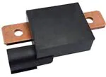
Power Metal Strip® Intelligent Battery Sensor
Very Low Value (100 μ)
FEATURES
• High voltage, current, and temperature range
• Can be ordered preprogrammed or blank
• Proprietary processing technique produces
extremely low resistance value
• Operates as a LIN 2.1 or 2.0 slave
• Circuit sealed for all weather use
• Variable sampling rate
• Capable of withstanding harsh automotive environments
• Integral 4-pin male connector (Molex # MX33482-4001)
• Very low inductance (< 5 nH)
• Material categorization: for definitions of compliance
please see www.vishay.com/doc?99912
APPLICATIONS
•
•
•
•
•
•
•
•
•
•
•
PRODUCT SUMMARY
Resistance
100 μ
Voltage range
4 V to 18 V
Current range (continuous)
± 600 A
Current range (pulsed)
± 2000 A
Temperature range
-40 °C to +115 °C
Automotive battery management systems
Lead acid battery monitoring
Uninterrupted power supplies
Golf carts
Electric forklifts
Personal mobility vehicles
Medical beds
Solar chargers
Renewable energy inverter systems
Recreational vehicles
Emergency lighting
GLOBAL PART NUMBER INFORMATION
GLOBAL PART NUMBERING: WBPK600L0A00010001 (WBP, 600 A, 0.000100 , A chipset, bulk pack)
W
B
P
K
6
0
GLOBAL
MODEL
(3 digits)
PACKAGING
CODE
(1 digits)
MAXIMUM
CONTINUOUS
CURRENT
(3 digit)
WBP
K = bulk pack
T = tray pack
001 thru 99K
as applicable
Revision: 05-Jan-17
0
L
0
COMMUNICATION
(1 digit)
l = LIN
A
0
0
0
SPECIAL
CHARACTER
(1 digit)
CHIPSET
CONTROLLER
(1 digit)
From 0 to 9
as applicable
A
1
0
0
0
1
DESIGN
(4 digits)
SOFTWARE
(4 digits)
0000 to 9999
as applicable
From 0 to 9999
as applicable
Document Number: 30194
1
For technical questions, contact: ww2cresistors@vishay.com
THIS DOCUMENT IS SUBJECT TO CHANGE WITHOUT NOTICE. THE PRODUCTS DESCRIBED HEREIN AND THIS DOCUMENT
ARE SUBJECT TO SPECIFIC DISCLAIMERS, SET FORTH AT www.vishay.com/doc?91000
�WBP
www.vishay.com
Vishay Dale
ABSOLUTE MAXIMUM RATINGS (all voltages referenced to GND = 0 V)
PARAMETER
UNIT
RATING
V
-22 to +40
V
-16 to +40
Vsup / Vmeas
LIN
LIN short-circuit current
mA
200
IN+
mV
-200 to +300
IN-
mV
-200 to +300
Operating temperature (1)
°C
-40 to +115
Storage temperature
°C
+150
Note
• Stresses beyond those listed under “Absolute Maximum Ratings” may cause permanent damage to the device. These are stress ratings
only, and functional operation of the device at these or any other conditions beyond those indicated in the operational sections of the
specifications is not implied. Exposure to absolute maximum rating conditions for extended periods may affect device reliability
RECOMMENDED OPERATING RANGE (all voltages referenced to GND = 0 V)
PARAMETER
UNIT
RATING
Vsup (1) / Vmeas
V
4 to 18
IN+
mV
± 200
IN-
mV
±5
Operating temperature (2)(3)
°C
-40 to +105
Notes
(1) LIN interface requires at least 7 V for functionality
(2) Temperature as measured by WBP output
(3) Reduced functionality above 105 °C may be experienced
TEMPERATURE ACCURACY
CURRENT VALUE PER GAIN RANGE
LOWEST I
(± A)
RANGE
HIGHEST I
(± A)
RESOLUTION
(mA)
1
0.0000
23.0718
0.7153
2
23.0719
46.1436
1.4305
3
46.1437
92.2873
2.8611
4
92.2874
184.5747
5.7222
5
184.5748
369.1495
11.4444
6
369.1496
738.2992
22.8887
7
738.2993
1476.5984
45.7775
8
1476.5985
2000.0000
91.5550
MAXIMUM CURRENT ERROR (CONTINUOUS)
MAXIMUM CURRENT ERROR (FULL RANGE)
12
3
Current Error (± A)
Current Error (± A)
3.5
2.5
2
1.5
1
10
8
6
4
0.5
2
0
0
0
200
400
Current Read (± A)
Revision: 05-Jan-17
600
0
500
1000
1500
2000
Current Read (± A)
Document Number: 30194
2
For technical questions, contact: ww2cresistors@vishay.com
THIS DOCUMENT IS SUBJECT TO CHANGE WITHOUT NOTICE. THE PRODUCTS DESCRIBED HEREIN AND THIS DOCUMENT
ARE SUBJECT TO SPECIFIC DISCLAIMERS, SET FORTH AT www.vishay.com/doc?91000
�WBP
www.vishay.com
Vishay Dale
SPECIFICATIONS
PARAMETER
UNIT
MIN.
TYP.
MAX.
POWER REQUIREMENTS
Supply voltage (Vsup)
Supply current (1)
V
4
12
18
mA
10
15
20
μ
95
100
105
CURRENT MEASUREMENT
Resistance
Current measurement range (continuous)
A
± 600
Current measurement range (pulsed) (2)
A
Maximum pulse energy (2)
J
900
Current measurement accuracy
A
± 0.5 % + offset
-2000
2000
Current measurement offset error max.
mA
-30
Current measurement resolution (see Table)
mA
0.715
0
91.5
30
18
VOLTAGE MEASUREMENT
Voltage measurement range
V
4
Voltage measurement accuracy
mV
-50
Voltage measurement resolution
mV
50
0.88
TEMPERATURE MEASUREMENT
Temperature measurement range
°C
-40
125
Temperature measurement accuracy (0 °C to 60 °C)
°C
±1
Temperature measurement accuracy (-20 °C to 100 °C)
°C
± 1.5
Temperature measurement accuracy (-40 °C to 115 °C)
°C
± 3.0
Temperature measurement resolution
°C
0.055
COMMUNICATION
LIN specification
LIN 2.1, 2.0
LIN baud rate
bits/s
Data transfer rate (max.) (3)
Hz
ADC sample rate (I, V, T)
Hz
2000
20000
50
10
200
1000
CONNECTIONS
Resistor mounting holes
Four pin connector
0.276" dia, centered widthwise, 0.492" from end of shunt
Integral connector mates to standard Molex 33472-4001 female connector
Notes
(1) Typical depends on LIN transfer rate
(2) Temperature as measured by the IBS may not exceed 115 °C
(3) LIN bus constrained
Revision: 05-Jan-17
Document Number: 30194
3
For technical questions, contact: ww2cresistors@vishay.com
THIS DOCUMENT IS SUBJECT TO CHANGE WITHOUT NOTICE. THE PRODUCTS DESCRIBED HEREIN AND THIS DOCUMENT
ARE SUBJECT TO SPECIFIC DISCLAIMERS, SET FORTH AT www.vishay.com/doc?91000
�WBP
www.vishay.com
Vishay Dale
DIMENSIONS in inches
PIN CONFIGURATION AND APPLICATION RECOMMENDATION
Revision: 05-Jan-17
Document Number: 30194
4
For technical questions, contact: ww2cresistors@vishay.com
THIS DOCUMENT IS SUBJECT TO CHANGE WITHOUT NOTICE. THE PRODUCTS DESCRIBED HEREIN AND THIS DOCUMENT
ARE SUBJECT TO SPECIFIC DISCLAIMERS, SET FORTH AT www.vishay.com/doc?91000
�WBP
www.vishay.com
Vishay Dale
PERFORMANCE
TEST
CONDITIONS OF TEST
Thermal shock (1)
-40 °C to + 85 °C, 500 cycles, 30 min at each extreme
High temperature exposure
+115 °C for 1000 h
High temperature operation
1000 h at +115 °C, 20 A at 1.5 h "ON", 0.5 h "OFF"
Low temperature operation
1000 h at -40 °C, 20 A at 1.5 h "ON", 0.5 h "OFF
Biased humidity
+85 °C, 85% RH, 1000 h (2)
Mechanical shock
100 g’s for 6 ms, 5 pulses
Vibration
Frequency varied 10 Hz to 2000 Hz in 1 min, 3 directions, 12 h
Moisture resistance
MIL-STD-202, method 106, 0 % power, 7b not required
Jump start test
26 V, 1 min overvoltage jump start simulation
Reverse polarity test
-13.5 V, 2 min reverse polarity jump start simulation
Over voltage test
18 V, 60 min overvoltage simulation
State change waveform test
State change susceptibility (on / off)
Ground path inductance sensitivity
State change susceptibility (on / off) due to ground path inductance
Notes
• All test are completed on a pass-fail basis, judged by compliance with the datasheet specifications
(1) 250 cycles unpowered, 250 powered
(2) Circuit powered
Revision: 05-Jan-17
Document Number: 30194
5
For technical questions, contact: ww2cresistors@vishay.com
THIS DOCUMENT IS SUBJECT TO CHANGE WITHOUT NOTICE. THE PRODUCTS DESCRIBED HEREIN AND THIS DOCUMENT
ARE SUBJECT TO SPECIFIC DISCLAIMERS, SET FORTH AT www.vishay.com/doc?91000
�Legal Disclaimer Notice
www.vishay.com
Vishay
Disclaimer
ALL PRODUCT, PRODUCT SPECIFICATIONS AND DATA ARE SUBJECT TO CHANGE WITHOUT NOTICE TO IMPROVE
RELIABILITY, FUNCTION OR DESIGN OR OTHERWISE.
Vishay Intertechnology, Inc., its affiliates, agents, and employees, and all persons acting on its or their behalf (collectively,
“Vishay”), disclaim any and all liability for any errors, inaccuracies or incompleteness contained in any datasheet or in any other
disclosure relating to any product.
Vishay makes no warranty, representation or guarantee regarding the suitability of the products for any particular purpose or
the continuing production of any product. To the maximum extent permitted by applicable law, Vishay disclaims (i) any and all
liability arising out of the application or use of any product, (ii) any and all liability, including without limitation special,
consequential or incidental damages, and (iii) any and all implied warranties, including warranties of fitness for particular
purpose, non-infringement and merchantability.
Statements regarding the suitability of products for certain types of applications are based on Vishay’s knowledge of
typical requirements that are often placed on Vishay products in generic applications. Such statements are not binding
statements about the suitability of products for a particular application. It is the customer’s responsibility to validate that a
particular product with the properties described in the product specification is suitable for use in a particular application.
Parameters provided in datasheets and / or specifications may vary in different applications and performance may vary over
time. All operating parameters, including typical parameters, must be validated for each customer application by the customer’s
technical experts. Product specifications do not expand or otherwise modify Vishay’s terms and conditions of purchase,
including but not limited to the warranty expressed therein.
Except as expressly indicated in writing, Vishay products are not designed for use in medical, life-saving, or life-sustaining
applications or for any other application in which the failure of the Vishay product could result in personal injury or death.
Customers using or selling Vishay products not expressly indicated for use in such applications do so at their own risk.
Please contact authorized Vishay personnel to obtain written terms and conditions regarding products designed for
such applications.
No license, express or implied, by estoppel or otherwise, to any intellectual property rights is granted by this document
or by any conduct of Vishay. Product names and markings noted herein may be trademarks of their respective owners.
© 2017 VISHAY INTERTECHNOLOGY, INC. ALL RIGHTS RESERVED
Revision: 08-Feb-17
1
Document Number: 91000
�


 工商网监
湘ICP备2023018690号
工商网监
湘ICP备2023018690号
