TWIF 085175, TWIF 085215, TWIF 085260
www.vishay.com
Vishay Draloric
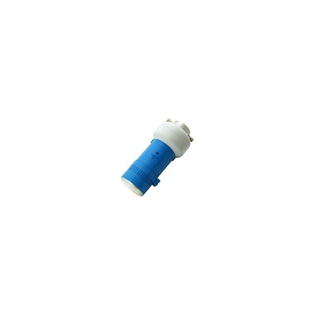
Watercooled RF Power Pot Capacitors
Internal Cooling System
FEATURES
• High voltage, current and power ratings
• Compact design reduces terminal self inductance and
permit operation up to higher frequencies
• These pot capacitors feature increased density through
watercooling and rugged mechanical construction for a
maximum reliability
APPLICATIONS
Watercooled RF power pot capacitors are designed for use
in the tank circuit of high power RF equipment such as
induction heating and welding equipment, dielectric heating
or a variety of specialized RF applications.
CAPACITANCE RANGE
1.0 nF to 4.7 nF
QUICK REFERENCE DATA
DESCRIPTION
VALUE
Ceramic Class
1
Ceramic Dielectric
CAPACITANCE TOLERANCE
± 20 %
R42, R85
Type
TWIF
085215
TWIF
085175
TWIF
085260
Voltage (Vp)
14 000
14 000
14 000
Min. Capacitance (pF)
1000
2200
4700
Max. Capacitance (pF)
1000
2200
4700
Mounting
Screw terminal
CERAMIC DIELECTRIC
• R42 (TCC - 250 ppm/K)
• R85 (TCC - 750 ppm/K)
RATED VOLTAGE
14 kVp
PRODUCT DESCRIPTION
DIELECTRIC STRENGTH TEST
TWIF pot-styled capacitors dissipate the heat produced
under load by means of water flow around the capacitor
elements. In order to provide protection from influences of
the chemical / physical characteristics of the coolant, a
glass passivation layer is applied over the cooled inner noble
metal electrode.
The electrical terminations are made directly to the noble
metal electrodes either utilizing special soldering
techniques or special clamping fittings. This method of
attachment provides a strong, rigid connection of
unsurpassed reliability. The TWIF pot-styled capacitors
feature an umbrella shaped insulating rim made from
silicone elastomer to minimize the adverse effects of
moisture, dust and other impurities in the working
environment and to improve the characteristics of the
electrical field. The capacitor body is protective lacquered.
200 % of rated voltage, 50 Hz
MARKING
Type designator, capacitance value and tolerance, rated RF
voltage, ceramic material code, production date code,
manufacturer logo, serial number.
RF POWER TEST
140 % to 180 % of rated power, for 10 minutes in a test
generator circuit
DISSIPATION FACTOR
Max. 0.05 %
Measuring frequencies:
300 kHz or 100 kHz
INSULATION RESISTANCE
Min. 10 000 M (at 25 °C)
OPERATING TEMPERATURE RANGE
Details of watercooling find under “Guidelines”, next pages
ACCESSORIES ADDED
All watercooled pot capacitors are supplied with
the necessary ferrules and 10 mm tube fittings for the water
supply connections.
Revision: 11-May-16
Document Number: 22166
1
For technical questions, contact: powcap@vishay.com
THIS DOCUMENT IS SUBJECT TO CHANGE WITHOUT NOTICE. THE PRODUCTS DESCRIBED HEREIN AND THIS DOCUMENT
ARE SUBJECT TO SPECIFIC DISCLAIMERS, SET FORTH AT www.vishay.com/doc?91000
�TWIF 085175, TWIF 085215, TWIF 085260
www.vishay.com
Vishay Draloric
SAP PART NUMBER AND ELECTRICAL DATA
PART NUMBER
WI085215WJ10238BH1
WI085175WJ22238BJ1
WI085260WJ47238BJ1
CERAMIC
CAP.
VALUES
(pF)
R42
1000
R85
RATED
VOLTAGE
(kVp)
RATED
POWER
(kvar)
RATED
CURRENT
(ARMS)
MIN. WATER
FLOW RATE
PER MINUTE
(Liter / US-gal.)
3.7 / 1.0
2200
14
1500
200
3.7 / 1.0
4700
4.5 / 1.2
Ø 55
(2.17 Dia.)
DIMENSIONS in millimeters (inches)
M8 thread holes
8 (0.31) depth
22 (0.87)
Water outlet
Connection terminal of the
inner electrode element
WI085215WJ10238BH1: 215 ± 2 (8.47 ± 0.08)
WI085260WJ47238BJ1: 260 ± 2 (10.24 ± 0.08)
WI085175WJ22238BJ1: 175 ± 2 (6.89 ± 0.08)
Water inlet
Moisture protection
(silicon rubber)
Ø 120 (4.72 Dia.)
Ø 85 (3.35 Dia.) ± 1 (0.039)
Installation position:
These capacitors are designed to be installed
in a vertical position, connection fittings of the
water cooling system upside.
Horizontal installation position is permissible,
whereby the water-outlet must be on top-side.
Connection terminal
of the outer
electrode
M
20 8 th
(0 rea
.8 d
0) h
de ole
pt s
h
Ø 64 (2.52 Dia.)
Thread holes M8
Ø 44
(1.73 Dia.)
Ø 88
(3.47 Dia.)
Revision: 11-May-16
Document Number: 22166
2
For technical questions, contact: powcap@vishay.com
THIS DOCUMENT IS SUBJECT TO CHANGE WITHOUT NOTICE. THE PRODUCTS DESCRIBED HEREIN AND THIS DOCUMENT
ARE SUBJECT TO SPECIFIC DISCLAIMERS, SET FORTH AT www.vishay.com/doc?91000
�TWIF 085175, TWIF 085215, TWIF 085260
www.vishay.com
Vishay Draloric
DERATING DIAGRAMS
WI085215WJ10238BH1
2.43 MHz 4.24 MHz
Ug (kVp)
100
Ig (ARMS)
Qg (kvar)
10 000
Ug
1000
10
Qg
100
1
Ig
10
0.1
0.1
1
10
100
Frequency (MHz)
WI085175WJ22238BJ1
Ig (ARMS)
Qg (kvar)
10 000
1.11 MHz 1.93 MHz
Ug (kVp)
100
Ug
1000
10
Qg
100
1
Ig
10
0.1
0.1
1
10
100
Frequency (MHz)
WI085260WJ47238BJ1
0.52 MHz 0.90 MHz
Ug (kVp)
100
Ig (ARMS)
Qg (kvar)
10 000
Ug
1000
10
1
100
Qg
Ig
0.1
0.01
10
0.1
1
10
Frequency (MHz)
Revision: 11-May-16
Document Number: 22166
3
For technical questions, contact: powcap@vishay.com
THIS DOCUMENT IS SUBJECT TO CHANGE WITHOUT NOTICE. THE PRODUCTS DESCRIBED HEREIN AND THIS DOCUMENT
ARE SUBJECT TO SPECIFIC DISCLAIMERS, SET FORTH AT www.vishay.com/doc?91000
�TWIF 085175, TWIF 085215, TWIF 085260
www.vishay.com
Vishay Draloric
GUIDELINES
ELECTRICAL DATA AND GUIDELINES
• The main physical and electrical characteristics of the capacitors and ceramic materials used, are listed in the tables on the
general section and in the individual datasheets.
• The continuous limit values of voltage, current, and power given in the diagrams must be observed.
• The rated voltage given in the tables is the peak value of the sinusoidal AC voltage or the sum of the DC and peak AC voltages
for which the capacitor is rated under continuous operation.
• The rated current in the tables is the effective value of the sinusoidal current for which the current paths of the capacitor are
designed.
INSTALLATION
• Watercooled pot capacitors (TWIF 085175, TWIF 085215, TWIF 085260) are designed to be installed in a vertical position,
connection fittings of the watercooling system upside. For large generators requiring multiple capacitors we recommended a
circular mounting pattern for optimum circuit performance.
• When capacitors are connected in parallel, care should be taken to mount the top electrodes of the capacitor away from the
RF bus bar to minimize the effects of stray electromagnetic fields. The capacitors elements must not exceed a temperature
of more than +100 °C.
• The electrical connection to the inner electrode must be flexible in order to prevent the generation of physical forces which
could damage the capacitor elements. Such forces are often generated by the dimensional differences resulting from the
normal physical tolerances of the capacitors. The capacitor’s inner electrode connector must not be used as a mechanical
support for other devices or components.
COOLING
• The cooling system is designed to operate at a maximum water pressure of 4 bars (58 psi).
• The position of water inlet and outlet is designed to be installed in a vertical position, connection fittings of the watercooling
system top-side. This allows any air to escape from the unit.
• The minimum water flow rates specified in the tables must be observed. When using antifreeze mixtures, the flow rate should
be increased by at least 20 %.
• The cooling system is designed to have a water temperature increase of < 10 °C (water inlet to water outlet) when the capacitor
is operated at full rated power and the minimum water flow rate. A water intake temperature of 30 °C is recommended. If
the cooling system of several capacitors is connected in series, the intake temperature of the coolant must not exceed 50 °C
for any capacitors.
• The pressure drop in a series connected cooling system is small. The table below illustrates the effects upon water flow rates
as a function of the number of series connected typical watercooled capacitors in the system with a constant intake water
pressure of 3 bars (43.5 psi).
Number of cooling systems in series
1
2
3
4
Water flow rate (liters/minute)
13.0
10.5
8.5
7.3
Water flow rate (US-gal./minute)
3.43
2.77
2.24
1.92
• Intake water temperature fluctuations in excess of 3 °C/s must be avoided to prevent damage to the capacitor elements.
• A coolant temperature rate monitor must provide a fail-safe on / off power control for the RF equipment.
• Normal tap water or de-mineralized water may be used for cooling. The water must be reasonably free of Ca CO3 and clear
of foreign particles or milkyness. The pH-value of the coolant should between 6 and 8.
Revision: 11-May-16
Document Number: 22166
4
For technical questions, contact: powcap@vishay.com
THIS DOCUMENT IS SUBJECT TO CHANGE WITHOUT NOTICE. THE PRODUCTS DESCRIBED HEREIN AND THIS DOCUMENT
ARE SUBJECT TO SPECIFIC DISCLAIMERS, SET FORTH AT www.vishay.com/doc?91000
�TWIF 085175, TWIF 085215, TWIF 085260
www.vishay.com
Vishay Draloric
QUALITY AND RELIABILITY
ELECTRICAL AND MECHANICAL SCREENING TESTS
All capacitors are subjected to the following tests prior to shipment
• Capacitance value (1.0 MHz or 0.1 MHz, 20 VRMS, 25 °C ± 5 °C)
• Dissipation factor (1.0 MHz or 0.3 MHz, 10 VRMS, 25 °C ± 5 °C)
• Insulation resistance (100 VDC, 25 °C ± 5 °C)
• Dielectric strength (200 % rated peak voltage, 50 Hz, 5 minutes)
• RF power test (140 % to 180 % rated power for 10 minutes in a test generator circuit)
• Pressure test (standard: 6 bars [87 psi] for 1 minute, 25 °C ± 5 °C)
WARRANTY STIPULATION FOR WATERCOOLED CERAMIC POWER RF CAPACITORS
• Unless otherwise provided for hereinafter, warranty shall be governed by General Terms of Sale and Delivery.
• Warranty is assumed for capacitors which fail to operate owing to faults in material or production, and within the warranty
period for capacitors.
• Excluded from warranty are capacitors prematurely rendered unserviceable owing to improper treatment, overloading, circuit
errors, as well as capacitors operated without observing the data given in our catalogue. Warranty is also excluded in cases
where faults can no longer be recognized on the capacitor owing to third party interferences. Warranty is only effectively
assumed when meeting the requirements referred to hereinafter.
• For claiming warranty, the defective capacitor should be returned to us, if possible in its original packing, within 14 days
following the data of failure, being accompanied by the completely filled-in and signed Original Guarantee Certificate. The
risks of transportation, as well as any shipping costs and other charges shall in any case be borne by the sender.
• Warranty can only become effective if the defective capacitor is received by us in the same condition as it was when it
happened to fail.
• We have the right to inspect any records proving the use of the capacitor.
• The decision as to whether we are obliged to assume warranty for the capacitor shall exclusively rest with us.
• When acknowledging the warranty claim, any non-repairable capacitor shall remain our property. When refusing a warranty
claim the defective capacitor will be returned at the customer’s expense only if demanded so explicitly when asserting the
warranty claim. In case examination required disassembly of the capacitor no claims for damage can be derived therefrom.
• The customer gives us the right to have the system checked in which the capacitor was operated.
• When acknowledging a warranty claim, restitution is made by supplying either a repaired and newly tested capacitor or by
supplying a new one.
• Warranty shall only extend to the capacitor itself. Any further claims for damages are excluded.
CONDITIONS OF GUARANTEE
Pursuant to the foregoing stipulations we assume warranty for these watercooled pot capacitors up to a period of 5000 hours
of operating service. Any claims for warranty, however will extinguish 24 months following the date of delivery.
RELATED DOCUMENTS
General Information
Revision: 11-May-16
www.vishay.com/doc?22071
Document Number: 22166
5
For technical questions, contact: powcap@vishay.com
THIS DOCUMENT IS SUBJECT TO CHANGE WITHOUT NOTICE. THE PRODUCTS DESCRIBED HEREIN AND THIS DOCUMENT
ARE SUBJECT TO SPECIFIC DISCLAIMERS, SET FORTH AT www.vishay.com/doc?91000
�Legal Disclaimer Notice
www.vishay.com
Vishay
Disclaimer
ALL PRODUCT, PRODUCT SPECIFICATIONS AND DATA ARE SUBJECT TO CHANGE WITHOUT NOTICE TO IMPROVE
RELIABILITY, FUNCTION OR DESIGN OR OTHERWISE.
Vishay Intertechnology, Inc., its affiliates, agents, and employees, and all persons acting on its or their behalf (collectively,
“Vishay”), disclaim any and all liability for any errors, inaccuracies or incompleteness contained in any datasheet or in any other
disclosure relating to any product.
Vishay makes no warranty, representation or guarantee regarding the suitability of the products for any particular purpose or
the continuing production of any product. To the maximum extent permitted by applicable law, Vishay disclaims (i) any and all
liability arising out of the application or use of any product, (ii) any and all liability, including without limitation special,
consequential or incidental damages, and (iii) any and all implied warranties, including warranties of fitness for particular
purpose, non-infringement and merchantability.
Statements regarding the suitability of products for certain types of applications are based on Vishay's knowledge of typical
requirements that are often placed on Vishay products in generic applications. Such statements are not binding statements
about the suitability of products for a particular application. It is the customer's responsibility to validate that a particular product
with the properties described in the product specification is suitable for use in a particular application. Parameters provided in
datasheets and / or specifications may vary in different applications and performance may vary over time. All operating
parameters, including typical parameters, must be validated for each customer application by the customer's technical experts.
Product specifications do not expand or otherwise modify Vishay's terms and conditions of purchase, including but not limited
to the warranty expressed therein.
Hyperlinks included in this datasheet may direct users to third-party websites. These links are provided as a convenience and
for informational purposes only. Inclusion of these hyperlinks does not constitute an endorsement or an approval by Vishay of
any of the products, services or opinions of the corporation, organization or individual associated with the third-party website.
Vishay disclaims any and all liability and bears no responsibility for the accuracy, legality or content of the third-party website
or for that of subsequent links.
Except as expressly indicated in writing, Vishay products are not designed for use in medical, life-saving, or life-sustaining
applications or for any other application in which the failure of the Vishay product could result in personal injury or death.
Customers using or selling Vishay products not expressly indicated for use in such applications do so at their own risk. Please
contact authorized Vishay personnel to obtain written terms and conditions regarding products designed for such applications.
No license, express or implied, by estoppel or otherwise, to any intellectual property rights is granted by this document or by
any conduct of Vishay. Product names and markings noted herein may be trademarks of their respective owners.
© 2021 VISHAY INTERTECHNOLOGY, INC. ALL RIGHTS RESERVED
Revision: 09-Jul-2021
1
Document Number: 91000
�