TB9102FNG
TOSHIBA Bi-CMOS Linear Integrated Circuit Silicon Monolithic
TB9102FNG
3ch H-bridge / 6ch Half-bridge driver for DC Brushed Motor
TB9102FNG is a 3chH-bridge / 6ch Half-bridge driver which
is designed specifically for Automotive. 6High-side/6Low-side
DMOS transistors are built-in for directly driving small DC
Brushed motor. SPI interface is built-in for motor operation by
external MCU. Also, miscellaneous abnormal detection
such as Over Current/Over Voltage/Over Temperature are
built-in. the TB9102FNG is for wide application such as for
Automotive Air-condition system (Dumper control), Door
Mirror control.
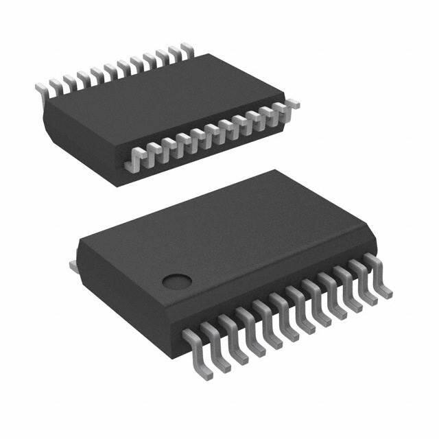
SSOP24-P-300-0.65A
Weight: 0.14 g (typ.)
Features
・Motor Driver
: Build-in 3ch H-bridge/6ch Half-bridge
(RHON=0.5Ω (typ.)/RLON=0.5Ω (typ.) at 25°C)
・External MCU I/F
: SPI Interface(16Bit Shift Register, CLK,CSB)
・Abnormal detection
: Over Current / Over Temperature / Over Voltage
/ 5V (VDD, VCC) Low Voltage Detection (Power on reset)
with monitoring by SPI I/F (output)
・Operating Voltage range (VM)
: 7 to 18V (Absolute maximum voltage: 40V)
・Operating Temperature range
: -40 °C to 125 °C
・Package: SSOP24-P-300-0.65A
・AEC-Q100 Qualified
・The product(s) is/are compatible with RoHS regulations (EU directive 2011 / 65 / EU) as indicated,
if any, on the packaging label ("[[G]]/RoHS COMPATIBLE", "[[G]]/RoHS [[Chemical symbol(s) of
controlled substance(s)]]", "RoHS COMPATIBLE" or "RoHS COMPATIBLE, [[Chemical symbol(s) of
controlled substance(s)]]>MCV").
©2014–2019
Toshiba Electronic Devices & Storage Corporation
1
2019-2-25
�TB9102FNG
Block Diagram
Over
Temp.
過熱
Detect
GNDA
VMA
VCC
Power ON
Reset
RESET
Over
Voltage
過電圧
Detect
Over
Current
過電流
Detect
OSC
(4MHz)
OA1
Over
Current
過電流
Detect
SPI I/F
& CONTROL LOGIC
VDD
OA2
VMBC
Over
過電流
Current
Detect
OB1
Over
Current
過電流
Detect
OB2
GNDB
Over
Current
過電流
Detect
MODE
SI
CLK
CSB
SO
OC1
GND
Over
Current
過電流
Detect
OC2
GNDC
SEL
TEST1 TEST2 TEST3
Note1: Some of the functional blocks, or circuit in the block diagram may be omitted or simplified for explanatory
purpose.
2
2019-2-25
�TB9102FNG
PIN Layout
OC1
1
24
VMBC
OC2
2
23
OB2
GNDC
3
22
OB1
TEST1
4
21
GNDB
SO
5
20
NC
SI
6
19
VMA
CLK
7
18
OA2
CSB
8
17
OA1
MODE
9
16
GNDA
SEL
10
15
TEST3
VDD
11
14
TEST2
VCC
12
13
GND
3
2019-2-25
�TB9102FNG
PIN Connection
PIN
No
PIN NAME
1
OC1
Half-bridge C Out1
OUT
2
OC2
Half-bridge C Out2
OUT
3
GNDC
GND for OC1,OC2
-
4
TEST1
TEST Input Pin
5
SO
SPI Output
6
SI
7
IN /
OUT
DESCRIPTION
IN
CIRCUIT
NOTE
Bip/HVMOS
RHON=RLON=0.5Ω(typ.)
(Note1)
Bip/HVMOS
RHON=RLON=0.5Ω(typ.)
(Note1)
Pull Down(100kΩ)
CMOS
Connect to GND on PCB
OUT
CMOS
SPI Input
IN
CMOS
Pull Down(100kΩ)
CLK
SPI Clock
IN
CMOS
Pull Down(100kΩ)
8
CSB
SPI CHIP Select
IN
CMOS
Pull Up(100kΩ)
9
MODE
10
11
12
13
SEL
VDD
VCC
GND
14
-
Normal/Standby or Brake
select Input
Sleep Mode Control
5V Input for CMOS LOGIC
5V input for Bipolar
GND for 5V
IN
CMOS
Pull Down(100kΩ)
IN
VDD
VDD
-
CMOS
-
Pull Down(100kΩ)
TEST2
TEST Output Pin
OUT
CMOS
Keep OPEN.
15
TEST3
TEST Input Pin
IN
CMOS
16
GNDA
GND for OA1,OA2
-
17
OA1
Half-bridge A Out1
OUT
18
OA2
Half-bridge A Out2
OUT
19
VMA
Power input for OA1,OA2
-
-
20
NC
No connection.
-
-
21
GNDB
GND for OB1,OB2
-
22
OB1
Half-bridge B Out1
OUT
23
OB2
Half-bridge B Out2
OUT
24
VMBC
Power input for OB1,2,
OC1,2
-
Connect VDD and VCC on
PCB
Pull Down(100kΩ)
Connect to GND on PCB
-
Bip/HVMOS
RHON=RLON=0.5Ω(typ.)
(Note1)
Bip/HVMOS
RHON=RLON=0.5Ω(typ.)
(Note1)
(Note2)
Keep OPEN
Bip/HVMOS
RHON=RLON=0.5Ω(typ.)
(Note1)
Bip/HVMOS
RHON=RLON=0.5Ω(typ.)
(Note1)
-
(Note2)
(Note1) HVMOS: Pch and Nch MOS which withstand voltage is the same as VMA,VMBC level
(Note2) Even if only using 1ch/2ch H-Bride (not using all 3ch H-bridge), VMA and VMBC should be connected to power
supply on the board.
4
2019-2-25
�TB9102FNG
Internal protection circuit
PIN No.
NAME
Internal Protection circuit
1
2
3
4
5
6
7
8
9
10
11
12
13
14
15
16
17
18
19
20
21
22
23
24
OC1
OC2
GNDC
TEST1
SO
SI
CLK
CSB
MODE
SEL
VDD
VCC
GND
TEST2
TEST3
GNDA
OA1
OA2
VMA
NC
GNDB
OB1
OB2
VMBC
C-Type
A-Type
A-Type.(for VCC)
A-Type
A-Type
A-Type
A-Type
A-Type
B-Type
B-Type
C-Type
A-Type.(for VCC)
A-Type
C-Type
B-Type
C-Type
B-Type
A-Type
C-Type
B-Type
VDD
or VCC
ESD_COM
ESD_
COM
VMA
(VMBC)
VCC
Bip
VMA
(VMBC)
VDD
VCC
GNDA
(GNDB,C)
VDD
Bip
CMOS
GND
Note1: VMA and VMBC are short-circuited internally.
Note2: GNDA, GNDB, GNDC and GND are short-circuited internally.
5
2019-2-25
�TB9102FNG
Functional Description
The TB9102FNG is a motor controller IC incorporating output driver, which is designed to operate
brushed small DC motor for automotive directly. It can be used as a 3ch H-bridge driver or a 6ch
Half-bridge driver. The motor control signal is inputted from the external MCU through SPI I/F. And
the signals of various abnormal detections such as over current detection, thermal shutdown circuit,
over voltage detection, and 5V-under voltage detection are outputted.
(1) SPI Interface control
The TB9102FNG has the SPI interface to control the motor by the external MCU. In SPI mode,
input data is stored to 16 Bit Shift register in synchronizing with the falling edge of CLK (clock). And
the data is outputted from SO terminal in synchronizing with the rising edge of CLK.
The detail is as follows.
(1)-1. SPI Communication
CSB: When “L” signal is inputted from external device, SPI communication is enable. Then, input
signal of “CLK” and “SI” can be read internally and data of SPI Status register Bit 15 is
outputted from the output SO. (1st bit is “Bit15”) When “CSB” is configured “L” to “H”, the
data of SPI Receive Register latching 16 Bit data inputted from SI at the rising edge is
transferred to the internal SPI Status register. Then, each data of Bit 1 to Bit 12 is
outputted from each motor output terminal as a motor output signal. While “CSB” is “H”,
“SO” is Hi-Z.
CLK: “CLK” is a clock terminal for SPI data communication which is inputted from external master
device. SPI data is outputted from SO in synchronizing with the rising edge of CLK and
read from SI in synchronizing with the falling edge of CLK.
SI: “SI” is a data input terminal for SPI communication which is inputted from external master
device. Input data is read at the falling edge of “CLK”. Thus, the IC changes the SPI input
data at the rising edge of “CLK”.
SO: “SO” is a output terminal for SPI data communication which is read by external master
device. While “CSB” is “H”, ”SO” is Hi-Z. When “CBS” is “L”, data of Bit0 to Bit15 of the
internal SPI Status register are outputted in synchronizing with the rising edge of the
inputted clock from CLK. After that, data is switched at the rising edge of CLK and outputted
from “SO”.
○ SPI DATA bit length error
When inappropriate length of data (more than 17 bits or less than 15 bits) are inputted because of
the communication error from MCU, all data of this cycle of this timing are ignored.
Sending and receiving data error should be detected by the master side, if necessary, and should
be treated appropriately.
6
2019-2-25
�TB9102FNG
(1)-2. SPI Communication protocol timing
When “CSB” is changed H to L, SPI Communication of TB9102FNG is enable ,read Input ”SI” and “CLK”, and then
outputs a predetermined data of SPI Status register from the output. (When “CSB” is “H”, SO is off (Hi-Z)
CSB
SPI 16bit data which are latched in sift register by “CLK” falling edge are sent to
internal SPI Status Register at “CSB” rising edge, then these data output from each
Motor control PIN OA1/2,OB1/2,OC1/2, then Motor start.
CLK
MSB
SI
15
LSB
14
12
13
11
10
9
8
7
6
5
4
3
2
1
0
14
15
13
After “CSB” being “L”, SPI input data from “SI” are read into internal sift register at “CLK” falling edge.
Thus, it is required that SPI input data(Master device) are sent and changed at “CLK” rising edge.
SO
15
14
13
12
11
10
9
8
7
6
5
4
3
2
1
0
14
15
13
After “CSB” being “L”, internal SPI Status register output 16bit data from “SO” at each “CLK”
rising edge. Received data in the master, make sure you like reads on the falling edge of CLK.
Hi-Z
Hi-Z
Bit12~1: Motor status monitor bit in SPI Status register)
(1)-3. SPI Communication timing chart
0.75*VDD
CSB
0.3*VDD
0.75*VDD
IN
SI bit15
SI
t DISU
t clkh
0.3*VDD
t DIHO
0.75*VDD
CLK
0.3*VDD
t lead
t log
t clkl
tVASO
t SODIS
t SOENA
SO
0.75*VDD
OUT
SO bit15
0.3*VDD
(Note)Timing charts may be simplified for explanatory purpose.
7
2019-2-25
�TB9102FNG
(1)-4. SPI Connection (Example)
More than two ICs can be controlled by connecting them as below figure and controlling “CSB” signal
of each IC.
(Master)
SI
Sift Register
(TB9102FNG)
SPI Rcv. Register
SPI Register
SO
SPI Clock
Generator
CLK
CSB
SPI Status register
Diag.
Cont.
Motor
Driver
Controller
SI
SPI Rcv. Register
SO
SPI Status register
CLK
CSB
Diag.
Cont.
8
Motor
Driver
Controller
2019-2-25
�TB9102FNG
(1)-5. SPI SI/SO Bit explanation
SI
Bit
15
14
Name
OVreset
OTreset
SO
Initial
Notes
Bit
L
H: Over voltage flag in SPI Status
register is reset and the operations of
all motor outputs, which are turned off
forcedly by the over voltage detection,
are returned to normal. However, in
case the operations are normalized
before the address of "H" is inputted,
each motor output has been already
returned to normal. By configuring both
Bit0 and Bit15 ”H”, internal SPI Status
register is reset at the rising edge of
“CSB”.
L: (No operation)
L
H: Over temperature flag in SPI Status
register is reset and the operations of
all motor outputs, which are turned off
forcedly by the thermal shutdown
circuit, are returned to normal.
However, in case the operations are
normalized before the address of "H" is
inputted, each motor output has been
already returned to normal.
L: (No operation)
13
OCfail
L
When the over current detection (1.5 A
(typ.)) operates, “H” is outputted from the
bit. Once the over current detection
operates, the bit keeps”H” until it is reset
by SPI “SI”Bit13 (OCreset) or Bit0/15.
15
14
Name
VMfail
OTfail
Initial
L
L
Notes
When the over voltage detection (26V
(typ.)) operates for the power supply of
H-bridge A (VMA), “H” is outputted from
the bit. Even if VMA returns to the normal
voltage (25.5 V (typ.)), the bit keeps”H”
until it is reset by SPI “SI”Bit15 or Bit0/15.
When the thermal shutdown circuit
(170°C(typ.)) operates, “H” is outputted
from the bit. Even if the temperature
returns to the normal value (160°C(typ.)),
the bit keeps ”H” until it is reset by SPI
“SI”Bit14 or Bit0/15.
13
OCreset
L
H: Over current flag in SPI Status
register is reset and the operations of
all motor outputs, which are turned off
forcedly by the over current detection,
are returned to normal.
12
C2Lcont.
L
Half-bridge C2 Low-side SW cont.
12
C2Lst
L
Half-bridge C2 Low-side SW status
11
C2Hcont.
L
Half-bridge C2 High-side SW cont.
11
C2Hst
L
Half-bridge C2 High-side SW status
10
C1Lcont.
L
Half-bridge C1 Low-side SW cont.
10
C1Lst
L
Half-bridge C1 Low-side SW status
9
C1Hcont.
L
Half-bridge C1 High-side SW cont.
9
C1Hst
L
Half-bridge C1 High-side SW status
8
B2Lcont.
L
Half-bridge B2 Low-side SW cont.
8
B2Lst
L
Half-bridge B2 Low-side SW status
7
B2Hcont.
L
Half-bridge B2 High-side SW cont.
7
B2Hst
L
Half-bridge B2 High-side SW status
6
B1Lcont.
L
Half-bridge B1 Low-side SW cont.
6
B1Lst
L
Half-bridge B1 Low-side SW status
5
B1Hcont.
L
Half-bridge B1 High-side SW cont.
5
B1Hst
L
Half-bridge B1 High-side SW status
4
A2Lcont.
L
Half-bridge A2 Low-side SW cont.
4
A2Lst
L
Half-bridge A2 Low-side SW status
3
A2Hcont.
L
Half-bridge A2 High-side SW cont.
3
A2Hst
L
Half-bridge A2 High-side SW status
2
A1Lcont.
L
Half-bridge A1 Low-side SW cont.
2
A1Lst
L
Half-bridge A1 Low-side SW status
1
A1Hcont
L
Half-bridge A1 High-side SW cont.
1
A1Hst
L
Half-bridge A1 High-side SW status
L
H: By configuring both Bit0 and
Bit15 ”H”, internal SPI Status register is
reset at the rising edge of “CSB”.
L: (No operation)
0
STreset1
(No operation and keep”L”)
0
9
(nop)
L
2019-2-25
�TB9102FNG
(SPI Input: SI)
Input data from SI terminal by SPI communication is read to the internal IC at the rising edge of the
CSB signal, and it is reflected on each function.
Bit0 (STreset1) / Bit15 (OVreset):
H: To avoid malfunction by noise, data of SPI Status register is reset by combining Bit0 and Bit15.
When only Bit0 reads “H”, any function is invalid. By resetting SPI Status register, each resulting
flag of abnormal detection in this resister is also reset. And the driving outputs of the motor, which
were turned off forcedly by the abnormal detection, are returned to the normal operation. In case
SPI Status register is reset, data of motor operation should be configured again because all
driving outputs of each motor become Hi-Z.
In resetting SPI Status register by Bit0 and Bit15, data of other bits of SI inputs sent at the same
timing (Bit1 to Bit12) are ignored. So, motor outputs should be configured at the next SPI
transmission after resetting SPI Status register by STreset.
L: No operation.
Bit1 to Bit12 (A1Hcont. to C2Lcont) :
On and Off of 12 transistors, which consists 3ch H-bridge and 6ch Half-bridge, are controlled. When
“H” level is inputted, the transistor which is controlled by the bit is turned on. When both High-side
transistor and Low-side transistor are turned on by the same Half-bridge, the Half-bridge output
becomes Hi-Z forcedly.
(Ex)
SI Bit 1=“H”
=“L”
Bit 2=“H”
=“L”
i.e.
SI Bit1=“H”,
Bit1=“L”,
Bit1=“L”,
Bit1=“H”,
: Half-bridge A1 H-side
:
〃
: Half-bridge A1 L- side
:
〃
Tr ON
Tr OFF
Tr ON
Tr OFF
Bit2=“L” : Half-bridge A=“H”
Bit2=“H” : Half-bridge A=“L”
Bit2=“L” : Half-bridge A= OFF (Hi-Z)
Bit2=“H” : Half-bridge A= OFF (Hi-Z)
Bit13 (OCreset):
Result flag of over current detection in SPI Status register is reset by inputting “H” to Bit13 (OCreset).
Motor drive output that is forced OFF by the overcurrent detection operates in accordance with the
Bit1 to Bit12 which are transmitted simultaneously with the Bit13.
H: The flag of the over current detection in the Status Flag is reset. Motor drive output that is forced
OFF by the overcurrent detection is released. After resetting over current detection, the motor
driver outputs in accordance with the Bit 1 to Bit12 of SPI signal which are transmitted
simultaneously with the Bit13.
L: No operation.
Bit14 (OTreset):
Result flag of thermal shutdown detection in SPI Status register is reset by inputting “H” to Bit14. All
motor drive outputs forced OFF by the thermal shutdown detection are returned to normal operation.
In this time, the motor drive outputs in accordance with the Bit1 to Bit12 which are transmitted
simultaneously by the SPI communication. Motor operation returns to the normal operation
automatically when the chip temperature falls to 160 °C or less. At that time, motor operation is
based on the data of Bit1 to Bit12 in the SPI Status register
H: The flag of thermal shutdown detection in the Status Flag is reset. Motor drive output that is
forced OFF by the thermal shutdown detection is released. Motor drive output that is forced OFF
by the thermal shutdown detection operates in accordance with the Bit1 to Bit12 of SPI signal
which are transmitted simultaneously with the Bit14.
L: No operation.
10
2019-2-25
�TB9102FNG
Bit15 (OVreset):
Result flag of over voltage detection in SPI Status register is reset by inputting “H” to Bit15. All motor
drive outputs forced OFF by the over voltage detection are returned to normal operation. In this time,
the motor drive outputs in accordance with the Bit1 to Bit12 which are transmitted simultaneously by
the SPI communication. Motor operation returns to the normal operation automatically when the
voltage falls to 25.5 V or less. At that time, motor operation is based on the data of Bit1 to Bit12 in
the SPI Status register
H: The flag of over voltage detection in the Status Flag is reset. Motor drive output that is forced
OFF by the over voltage detection is released. Motor drive output that is forced OFF by the over
voltage detection operates in accordance with the Bit1 to Bit12 of SPI signal which are
transmitted simultaneously with the Bit15.
L: No operation.
(SPI Output: SO)
Bit1 to Bit12 (A1Hst to C2Lst):
The outputting state of 12 transistors consisting 3ch of H-bridge is outputted.
H: Transistor ON
L: Transistor OFF (Hi-Z)
Bit13 (OCfail):
When over current (1.5A (typ.)) is detected on each H-bridge Driver, “H” level is outputted. Refer to
(5)-3 for over current detection. Once the over current is detected, this flag is kept “H” until SPI
Status register is reset by setting SI Bit0(STrest1) and Bit15(OVreset) “H” at the same time or OC is
reset by setting Bit13(OCreset) “H”.
(The state of “H” of Bit13 is kept though the current of LSI decreases less than the detecting value.)
Bit14 (OTfail):
When over temperature (170°C (typ.)) is detected, “H” level is outputted. Refer to (5)-4 for thermal
shutdown detection. Once the over temperature is detected, this flag is kept “H” until SPI Status
register is reset by setting SI Bit0 (STrest1) and Bit15 (OVreset) “H” at the same time or OC is reset
by setting Bit14 (OTreset) “H”.
(The state of “H” of Bit14 is kept though the temperature of LSI decreases less than the detecting
value.)
Bit15 (VMfail):
When the over voltage of VMA (26V (typ.)) is detected by monitoring the power supply of H-bridge A
(VMA), “H” level is outputted. Refer to (5)-2 for over voltage detection. Once the over voltage is
detected, this flag is kept “H” until SPI Status register is reset by setting SI Bit0 (STrest1) and Bit15
(OVreset) “H” at the same time or OC is reset by setting Bit15 (OVreset) “H”.
(The state of “H” of Bit15 is kept though VMA decreases less than the detecting value.)
11
2019-2-25
�TB9102FNG
SPI Data
SPI interface is enabled when CSB is set ”H” to L.
The data is outputted from the SO at the rising edge of CLK. Then the SI input data is read to the
internal shift register at the falling edge of CLK.
CSB
SI
SI[15] SI[14] SI[13] SI[12] SI[11] SI[10] SI[9] SI[8] SI[7] SI[6] SI[5] SI[4] SI[3] SI[2] SI[1] SI[0]
ST
OV
OT
OC
OC2:L OC2:H OC1:L OC1:H OB2:L OB2:H OB1:L OB1:H OA2:L OA2:H OA1:L OA1:H
RESET
RESET RESET RESET
CLK
So
So[15] So[14] So[13] So[12] So[11] So[10] So[9] So[8] So[7] So[6] So[5] So[4] So[3] So[2] So[1] So[0]
VM
fail
OT
fail
OC
fail
OC2L OC2H OC1L OC1H OB2L OB2H OB1L OB1H OA2L OA2H OA1L OA1H
:status :status :status :status :status :status :status :status :status :status :status :status Nop:Lo
SI Data and SO Data
The status of SO output data is shown in the below figure.
CLK
SI
So
1st set
2nd set
3rd set
1st DATA
2nd DATA
12
2019-2-25
�TB9102FNG
(2) STANDBY MODE / BRAKE MODE (“MODE” terminal / “SEL” terminal)
The STANDBY mode and BRAKE mode can be selected by input terminal of “SEL”, and can move to
each mode by setting input terminal of ”MODE” to “L”. Refer to below table for the detail of each mode.
“MODE” terminal and “SEL” terminal incorporate pull-down resistance.
(Brake Mode in the table indicates the case the IC is used as a 3ch H-bridge.)
MODE
“MODE”
terminal
“SEL”
terminal
Operation of motor
output circuit
Input data and power supply
of each analog circuit
Normal
H
H/L
(OPEN)
Normal
Normal
BRAKE
L
(OPEN)
H
H-side: OFF(Hi-Z)
L-side: ON
Each Input data: KEEP
Analog circuit: OPERATE
STANDBY
L
(OPEN)
L
(OPEN)
H-side: OFF(Hi-Z)
L-side: OFF(Hi-Z)
Each input data: Lost (Clear)
Analog circuit: STOP
Note1: All of the above operations are under the conditions that the external power supplies of
VMA, VMBC, VDD, and VCC are always supplied
Note2: When the input terminal of SEL is configured “L” or open in the BRAKE mode, the operation
can move to the standby mode directly. However, when the input terminal of SEL is
configured ”H” in the standby mode, the input data is ignored and the operation does not
move to the BRAKE mode. In the standby mode, the abnormal detecting functions are
turned off. In the standby mode, operations of all circuits including analog circuits are turned
off and each input data are cleared (initial). So, as described above, in the standby mode,
the input data are ignored though the input terminal of SEL is configured “H” and the
operation does not move to the BRAKE mode. When it is necessary to move the operation
from the standby mode to the brake mode, please set the operation to the normal mode
and then set the brake mode. In this time, the time to start up the analog circuit is needed.
Note3: When use the IC in the standby mode with the MODE terminal by fixing the SEL terminal,
please avoid generating the BEF(Back Electromotive Force) by turning on the low side of
the H-bridge circuit by SI input signal and braking before moving to the standby mode.
Otherwise, there is a possibility to damage the IC by BEF (Back Electromotive Force) if the
operation is configured from motor rotating to the standby mode directly. Regardless of the
input signal SI, the brake mode stops the motor output (HVMOS) directly.
13
2019-2-25
�TB9102FNG
●Example: each mode (only 1ch H-bridge)
STANDBY mode
BRAKE mode
VM
OFF
VM
OFF
OFF
OFF
M
OFF
M
OFF
ON
ON
Note1: When the mode is changed by the input terminal of “SEL” or “MODE” during SPI
transmission, the SPI communication is stopped and all of the input data which are already
sent to the TB9102FNG are ignored. Then, the mode is transmitted according to the input
data.
Note2: Cautions in using the MODE terminal and the SEL terminal are written below.
• Brake mode
When the mode moves to the brake mode by using MODE terminal, SPI register data are
stored.
Therefore, the motor operates according to the previous SPI register data until new data is
written to the SPI resister after releasing BRAKE mode and finishing 2nd SPI transmission.
When the motor need to be operated differently just after releasing BRAKE, release BRAKE
(set the MODE terminal “L” to “H”) just before the rising edge of CSB of 1st SPI transmission.
• Standby mode
When the mode is moved to the standby mode by combining the “L” setting of the MODE
terminal and “L” setting of the SEL terminal, all of data configured by SPI transmission are
reset (cleared).
Therefore, function should be configured again by SPI transmission after the standby mode is
released. Data is not read if SPI is transmitted during the standby mode.
・Case1: Brake ON/OFF
CSB
SPI
communication
Function 1
Register
MODE
Brake
SEL
Motor
out
Function1
14
Brake
Function1
2019-2-25
�TB9102FNG
・Case 2: New SPI transmission after releasing Brake
CSB
SPI
communication
SPI
communication
Function2
Function1
Register
MODE
Brake
SEL
Motor
out
Function1
Brake
Function2
・Case3: Function after releasing the standby
CSB
SPI
communication
SPI
communication
Clear
(Initial Data)
Function1
Register
Function2
MODE
SEL
Standby
Motor
out
Clear
(Initial Data)
Function1
Function2
(3) DEAD TIME
The TB9102FNG generates 1μsec (typ.) of Hi-Z state to avoid the short circuit due to “ON” of both
High-side and Low-side consisting each Half-bridge in each H-bridge. The state of Hi-Z is generated
when HVMOS changes from OFF to ON as shown below. When both High-side and Low-side of the
same Half-bridge are turned on by SPI communication, output of the Half-bridge becomes Hi-Z.
SPI Status Reg.内
Half-Bridge
H-side
データ
DATA
L-side
データ
DATA
H
L
H
L
H
L
H
ON
OFF
ON
OFF
OFF
ON
OFF
OFF
H
Half-Bridge
H-side
Pch OUTPUT
(Pch)出力
OFF
L-side
Nch OUTPUT
(Nch)出力
1μs
(typ.)
1μs
(typ.)
OFF
(Hi-Z)
Half-Bridge出力
Half-bridge
OUTPUT
15
2019-2-25
�TB9102FNG
(4) Motor Driver
Each Half-bridge has the following construction.
Example: H-Bridge (OA)
VM
A2 Hi-side
0.5Ω(typ)
A1 Hi-side
0.5Ω(typ)
Motor
A2 Lo-side
0.5Ω(typ)
A1 Lo-side
0.5Ω(typ)
(5) Abnormal Detection
(5)-1. Under Voltage Detection circuit for 5V power supply (VCC and VDD supplies)
(Internal power on reset)
It monitors the externally applied voltage basing on internal band gap voltage and detect the under
voltage. When 5V power supply VCC (VDD) falls to the detection voltage (4.0V (typ.)) or less, All
circuits of the TB9102FNG are reset internally and driver outputs are turned off (Hi-Z). When VCC
rises over returning voltage (4.1V (typ.)), the detection is released and the TB9102FNG returns to
the normal operation from the initial state. The detection and return voltages have the hysteresis
(Refer to “Electrical Specification).
And the internal detection and return signals incorporate the protection circuit against chattering to
avoid malfunction.
POR OFF
POR OFF
5V (VCC)
POR ON
Analog Circuit
start Viltage
Normal
Operation
Voltage Up
Voltage
Drop
Normal
operartion
Power On
(rising)
POR ON
0V
Internal
Reset signal
RESET
OSC
RESET
OFF
ON
16
ON
2019-2-25
�TB9102FNG
(5)-2.
Over Voltage Detection for power supply of H-bridge (VMA) driver (26V (typ.))
The TB9102FNG incorporates the over voltage detection circuit for H-bridge A based on the
internal band gap voltage. When H-bridge A voltage (VMA) rises over 26V (typ.), all outputs of
H-bridge are turned off (Hi-Z) to protect the driver from over voltage. “H” is outputted by Bit15 of
SPI Status register output (SO).
When VMA falls to releasing voltage (25.5V (typ.)) or less, outputs of H-bridge, which are turned off
forcedly, returns to the normal operation according to the data of SPI Status register. The flag of
SPI Status register keeps “H”. This flag can be released by inputting “H” to both Bit0 and Bit15 of SI
at the same time (SPI Status register Reset) or inputting “H” to Bit15(OVreset).
In case of SPI Status register Reset, data of Bit1 to Bit12 transmitted at the same time are ignored.
So, the motor output should be configured by the following SPI transmission.
Internal detection and release signals of over voltage detection have the protection circuit against
chattering to avoid malfunction. So, even if the over voltage detection is released, the over voltage
is detected again and all motor outputs are turned off (Hi-Z) when the voltage continues to exceed
the over voltage detection value.
26V
VMA
OV Flag
Over Voltage
detect
Motor return
to normal
operation
25.5V
SPI Status Register Flag,
SPI SO Bit 15 “H”
Motor OUTPUT OFF
Motor normal
operation return
SPI SI bit15 ”H”
OV Flag off
【 CAUTION 】 This over voltage detection does not clamp the power supply voltage of the
TB9102FNG.
Therefore, VMA and other power supplies should be protected externally not to
exceed the absolute maximum rating. VMA should be connected to VMBC power
supply or GND (GNDA, GNB, and GNC) externally, even in case of using 1ch and
2ch of H-bridge only. If VMA is not connected on PCB, over voltage detection does
not operate.
17
2019-2-25
�TB9102FNG
(5)-3. Over Current Detection for Driver (1.5A (typ.))
The TB9102FNG incorporates the over current detection for each High-side and Low-side driver,
which consists each Half-bridge of the H-bridge circuit. When output current of ±1.5A (typ.) or more
flows in one of the drivers, the driver output detected by the over current detection is turned off. And
“H” is outputted by SPI output (SO) Bit13.
Once the over current is detected, the transistor continues to turn OFF (Hi-Z), if the current falls to
the normal level. The over current detection is reset by inputting “H” to SPI SI Bit0 and Bit15 at the
same time (SPI Status register Reset) or by inputting “H” to Bit13 (Ocreset). The configuration after
resetting the over current detection by SI Bit0, Bit15, and Bit13 is described below.
STreset: All SPI Status registers are reset at the rising edge of the clock CSB by inputting
“H” to both Bit0 and Bit15. Then, all outputs of each motor driver are turned off (Bit
of OFF state keeps OFF). In this time, data of Bit1 to Bit12, which are transmitted
at the same timing of Bit0 and Bit15, are ignored. So, configure the motor output
by the next SPI transmission after resetting SPI Status register by Streset.
OCreset: Over current detection state is reset by inputting “H”. In this time, data of Bit1 to
Bit12 transmitted at the same time are valid and the motor output is configured by
these Bit data.
Internal detection and release signals of the over current detection have protection circuit against
chattering to avoid malfunction. Even after the above reset for over current detection, if the over
current state continues, the over current detection operates again and the output of motor driver is
turned off again.
CSB
The data is reset in the
rising of a CSB edge.
Over Current Detect
Driver
Current
Transistor OFF(Hi-Z)
Keep OC Flag
OC Flag
SPI Status Register Flag,
SPI SO Bit13 “H”
Motor OUTPUT OFF
Note: The over current detection circuit is only intended to provide temporary protection against
irregular conditions such as an output short-circuit. It does not necessarily guarantee the
complete IC safety. Therefore, utmost care is necessary in the design of the output lines, VCC,
and GND lines since the IC may be destroyed by short-circuiting between outputs, air
contamination faults, or faults due to improper grounding, or by short-circuiting between
contiguous terminals.
18
2019-2-25
�TB9102FNG
(5)-4. Thermal shutdown detection (170°C (typ.))
The TB9102FNG incorporates the thermal shutdown detection which monitors the temperature of
the internal IC chip near the driver output circuit for the motor. When the chip temperature rises
170°C (typ.) or more, all driver outputs are turned off (Hi-Z) and Bit14 of SPI Status register Output
(SO) is set to “H”. When the temperature falls to 160°C (typ.) or less after thermal shutdown circuit
operates, H-bridge driver outputs, which were turned off forcedly, return to the normal operation
according to the data of SPI Status register. The flag of Bit14 of SPI Status register is kept “H”. The
flag is released when “H” is inputted to SPI SI Bit14 (OTreset) or to both Bit 0 and Bit15 (Streset). In
case of SPI Status register reset, data of Bit1 to Bit12, which were transmitted at the same timing of
Bit0 and Bit15, are ignored. So, configure the motor output by the next SPI transmission after
resetting the thermal shutdown detection.
Internal detection and release signals of the thermal shutdown detection have protection circuit
against chattering to avoid malfunction. Even after the above reset for thermal shutdown detection,
if the over temperature state continues, the thermal shutdown detection operates again and the
output of motor driver is turned off (Hi-Z) again.
170℃
CHIP
TEMP
OT Flag
CHIP Temp.
over detect
Motor return
to normal
operation
160℃
SPI Status Register Flag,
SPI SO Bit 14 “H”
Motor OUTPUT OFF
Motor normal
operation return
SPI SI bit15 ”H”
OT Flag off
Note: The Absolute maximum temperature of the TB9102FNG is 150°C. The absolute maximum
temperature is never exceeded in using and storing the TB9102FNG. If any of the rating
would be exceeded, the normal operation of the IC can no longer be guaranteed. Moreover,
exceeding the absolute maximum rating may cause smoke or ignition of the device. Do not
exceed any of the absolute maximum rating.
Though this IC incorporates thermal shutdown detection, this function does not reduce the
over temperature of the IC (below 170 °C). It is a subservient function for the out of the range
of the operating guarantee.
(As for this function, shipping test is not performed at the actual temperature individually.
Operation of the thermal shutdown detection is pseudo-confirmed by the TEST function.)
(6) Internal Oscillator (4MHz (typ.))
The TB9102FNG incorporates the oscillation circuit of 4MHz (typ.) for operation of the internal circuit.
It is used for generation of basic clock of the internal logic circuit and DEAD TIME, and for each
abnormal detection circuit.
Pay attention that in STANDBY mode, this oscillation circuit is turned off and each abnormal detection
circuit does not work.
19
2019-2-25
�TB9102FNG
(7) Electrical Characteristics
MAXIMUM ABSOLUTE RATINGS (Ta=25°C)
ITEM
SYMBOL
VM
VDD, VCC
Supply Voltage
Output Current
IOUT
Input/Output Voltage
VIN, VOUT
Storage Temperature
Tstg
Soldering Temperature
Tsol
PIN
VMA, VMBC
VDD ,VCC
OA1, OA2, OB1, OB2,
OC1, OC2
OA1, OA2, OB1, OB2,
OC1, OC2
SO
CONDITION
DC Voltage
DC Voltage
at Over Current
Detection
-
RATING
-0.3 to +40
-0.3 to +6.0
±1.5
-
±10
-
-0.3 to VDD+0.3
(max: 6V)
TEST1, TEST3
SEL, CSB, CLK, SI,
MODE
OA1, OA2, OB1, OB2,
OC1, OC2
SO, TEST2
V
A
±1.0
Note2
mA
V
-0.3 to VM
(max: 40V)
-0.3 to VDD+0.3
(max: 6V)
-55 to +150
-
-
UNIT
-
V
°C
Manual Soldering
260(10s)
PCB 76.2×114.3×t1.6
Max Power Dissipation
PD
1.32
Mono Layer, Cu: 30%
CAUTION 1: The above current spec. value of “+” is Input from outside,”-“ is Output from TB9102FNG.
W
CAUTION 2: Please do not exceed the absolute maximum rating, including the reverse voltage.
CAUTION 3: The absolute maximum ratings of a semiconductor device are a set of specified parameter values, which must
not be exceeded during operation, even for an instant.
If any of these rating would be exceeded during
operation, the device electrical characteristics may be irreparably altered and the reliability and lifetime of the
device can no longer be guaranteed. Moreover, these operations with exceeded ratings may cause break
down, damage and/or degradation to any other equipment. Applications using the device should be designed
such that each maximum rating will never be exceeded in any operating conditions. Before using, creating
and/or producing designs, refer to and comply with the precautions and conditions set forth in these
documents.
Package (SSOP24-P-300-0.65A)
SYMBOL
ITEM
Thermal Resistance
Rθj-a
Thermal Resistance
RATING
CONDITION
UNIT
160
IC
°C/W
PCB 1Layer, size:76.2×114.3×t1.6mm,
95
Cu:30%, Cu thickness:35μm
PCB 4Layer, size:76.2×114.3×t1.6mm
60
(1)
PD (W)
1.32
PD max - Ta(Reference Data)
°C/W
PCB size:76.2×114.3×1.6mm
Cu 30%,Mono Layer
PD = (150 - Ta)/Rθj-a
I C (Single)
0.78
IC(no PCB) at 25°C.
(150-25)/160 = 0.781 (W)
0.67
using PCB(Mono Layer) size: 76.2×114.3×1.6mm
Cu 30% at 25°C.
(150-25)/95 = 1.32(W)
0.53
0.24
0.16
0
Cu:30%, Cu thickness:35μm
°C/W
25
85
125
150
Ta (°C)
20
2019-2-25
�TB9102FNG
(7) Electrical Characteristics (cont.)
Operating Range
ITEM
Supply Voltage
Operating
Temperature
SYMBOL
RATING
VM
7 to 18
VDD,VCC
4.5 to 5.5
Topr
-40 to 125
UNIT
NOTES
-
V
Operating range of 5V circuit
(Logic circuit, Bipolar)
°C
-
IC Characteristics
The following are under condition VMA=VMBC=7 to 18V, VDD=VCC=4.5 to 5.5V, Ta=-40 to 125°C. unless otherwise
specified
ITEM
Current
Consumption
(operation)
Symbol
PIN
CONDITION
OA1/2,OB1/2,OC1/2
: OPEN(no load)
(Logic circuit only)
at Standby mode(CSB=H,
CLK=SI=SEL=MODE=L)
each Motor off
MIN
TYP
MAX
UNIT
I(VM)
VMA, VMBC
-
1.0
6.0
mA
I(VDD+VCC)
VDD, VCC
-
1.4
2.0
mA
Istby(VM)
VMA, VMBC
-
1.0
30
μA
Istby(VDD
+VCC)
VDD,VCC
-
-
3.0
10
μA
VOL(SO)
SO
IOL=2.5mA
-
0.05
0.4
V
VOH(SO)
SO
IOH= -2.5mA
VDD-0.6
VDD-0.05
-
V
IO(OFF)
SO
CSB=H
-3
-
3
μA
IIL1
CSB
-100
-50
-10
-10
-
10
-10
-
10
10
50
100
-
-
-
0.3*VDD
-
0.75*VDD
-
-
-
-
0.5
-
Standby Current
Output Voltage
Level “L”
Output Voltage
Level “H”
Output OFF Leak
Current
Input Current
Level “L”
IIL2
IIH1
Input Current
Level ”H”
Input Voltage
Level ”L”
Input Voltage
Level ”H”
Hysteresis of
Input Voltage
IIH2
SI,CLK,
MODE, SEL
CSB
SI,CLK,
MODE,SEL
VIN=VDD
VIL1
VIH1
μA
VIN=0V
MODE,SI,CLK,
CSB,SEL
VHYS1
21
μA
V
2019-2-25
�TB9102FNG
(7) Electrical Characteristics (cont.)
Motor Driver
The following are under condition VMA=VMBC=7 to 18V, VDD=VCC=4.5 to 5.5V, Ta=-40 to 125°C. unless otherwise
specified
ITEM
Symbol
High-side Output
ON Resistance
RHON
Low-side Output
ON Resistance
Output OFF Leak
Current
RLON
PIN
OA1,OA2
OB1,OB2
OC1,OC2
ILO
CONDITION
IOUT=-0.5A,Ta=+25°C
IOUT=-0.5A,Ta=125°C
IOUT=-0.5A,Ta=-40°C
IOUT=+0.5A,Ta=+25°C
IOUT=+0.5A,Ta=125°C
IOUT=+0.5A,Ta=-40°C
Output OFF,VOUT=0V
Ta=25°C
Ta=-40 to 125°C
Output OFF,VOUT=VM
Ta=25°C
Ta=-40 to 125°C
MIN
-
TYP
0.5
0.7
0.4
0.5
0.6
0.3
MAX
0.8
1.2
0.6
0.8
1.2
0.6
-1
-
-
-5
-
-
-
-
1
-
-
5
-
UNIT
Ω
μA
Note1: When Motor is rotated, it makes Electromotive Force. The Electrical Specification must be kept, even with
this Electromotive Force.
Abnormal Detection
The following are under condition VMA=VMBC=7 to 18V, VDD=VCC=4.5 to 5.5V, Ta=-40 to 125°C. unless otherwise
specified
ITEM
Symbol
PIN
CONDITION
MIN
TYP
MAX
UNIT
Under Voltage
Detection circuit
VRSTH
RESET OFF Voltage
of VCC
Under Voltage
VCC
Detection circuit
VRSTL
RESET ON Voltage of
VCC
RESET Hysteresis
VRSTHYS
Voltage
Over current detection
Current
ISLMAX
OA1,OA2
(“-” short)
OB1,OB2
Over Current
OC1,OC2
Detection Current
ISHMAX
(“+” short)
Over Voltage
VSDH
Detection ON
VMA,VMBC
Over Voltage
VSDL
Detection OFF
Over Temp.
OA1,OA2
TSDH
Detection ON
OB1,OB2
Over Temp. Hysteresis TSDHYS
OC1,OC2
-
3.9
4.1
4.3
V
-
3.8
4.0
4.2
V
VRSTHYS=VRSTH-VRSTL
-
0.1
-
V
-
-2.5
-1.6
-1.0
A
-
1.0
1.5
2.5
24.5
26.0
27.5
24.0
25.5
27.0
155
170
-
-
10
-
Motor no load
Note2: Design value
V
°C
Note2: This Temperature detection function is only checked by circuit simulation, it is not tested on production.
22
2019-2-25
�TB9102FNG
(7) Electrical Characteristics (cont.)
AC Characteristics: Motor Output Delay time
The following are under condition VMA=VMBC=7 to 18V, VDD=VCC=4.5 to 5.5V, Ta=-40 to 125°C. unless otherwise
specified
ITEM
Source(High-side)
ON time
Symbol
tdO(on)
Source(High-side)
OFF time
tdO(off)
Sink(Low-side)
ON time
tO(on)
Sink(Low-side)
OFF time
tO(off)
DEAD TIME
Source(High-side)
Rising time
Source(High-side)
Falling time
Sink(Low-side)
Rising time
Sink(Low-side)
Falling time
PIN
CSB
OA1,OA2
OB1,OB2
OC1,OC2
CONDITION
MIN
TYP
MAX
Rload=100Ω
-
4.5
7.0
Rload=100Ω
-
2.5
4.0
μs
Rload=100Ω
-
4.5
7.0
Rload=100Ω
-
2.5
4.0
tDEAD
-
-
2.0
-
tr(sou)
Rload=100Ω
-
5.0
9.0
Rload=100Ω
-
0.2
0.5
Rload=100Ω
-
0.2
0.5
Rload=100Ω
-
4.0
8.0
tf(sou)
tr(sin)
OA1,OA2
OB1,OB2
OC1,OC2
tf(sin)
UNIT
μs
μs
AC Time chart of Motor output delay time
CLK
SI
70%
CSB
tf(sou)
OA,
OB,
OC
OA,
OB,
OC
OA,
OB,
OC
Source(High-Side)
ON to OFF(refer to fig1)
90%
10%
tdO(off)
tf(sin)
10%
tO(on)
tr(sou)
tDEAD
Source(High-Side)
OFF to ON(refer to fig2)
90%
10%
tdO(on)
tO(off)
OA,
OB,
OC
90%
tDEAD
Sink(Low-Side)
OFF to ON( refer to fig1)
tr(sin)
Sink(Low-Side)
ON to OFF(refer to fig2)
90%
10%
23
2019-2-25
�TB9102FNG
AC timing measurement circuit
Fig1
VM
Fig2
ON→OFF
VM
100kΩ
OFF
ON→OFF
OFF
100kΩ
VM
VM
OFF
100kΩ
OFF→ON
OFF→ON
OFF
100kΩ
Note1: Components in the test circuits are only used to obtain and confirm the device characteristics.
These components and circuits do not warrant to prevent the application equipment from malfunction or
failure.
Note2: Timing charts may be simplified for explanatory purpose.
SPI Delay Time
The following are under condition VMA=VMBC=7 to 18V, VDD=VCC=4.5 to 5.5V, Ta=-40 to 125°C unless otherwise
f specified
ITEM
CLK Frequency
CLK High Time
CLK LOW Time
CSB↓-CLK↑Set Up
Time
CLK↓-CSB↑Set Up
Time
SISet Up Time
SI Hold Time
SO EnableTime
SO Valid Time
Symbol
tpclk
tclkh
tclkl
PIN
CONDITION
-
MIN
250
250
TYP
-
MAX
1.0
-
UNIT
MHz
-
10
-
-
μs
-
100
-
-
ns
CLK,SI
-
SO,CSB
SI, SO
CL=100pF
CL=100pF
125
125
-
-
10
125
CLK
tlead
CSB,CLK
tlag
tDISU
tDIHO
tSOENA
tVASO
ns
ns
ns
ns
0.75*VDD
CSB
0.3*VDD
0.75*VDD
IN
SI bit15
SI
t DISU
t clkh
0.3*VDD
t DIHO
0.75*VDD
CLK
0.3*VDD
t lead
t log
t clkl
tVASO
t SOENA
SO
0.75*VDD
OUT
SO bit15
0.3*VDD
24
2019-2-25
�TB9102FNG
Application circuit diagram (1) 3ch H-bridge use
Reg.
5V
BATTERY
Over Temp.
Detect
GNDA
VMA
Over
Voltage
Detect
VCC
Power On
Reset
OSC
(4MHz)
Over
Current
OA1
OA2
Over
Current
VMBC
Over
Current
OB1
M
OB2
Over
Current
GNDB
Over
Current
VDD
SPI I/F
& CONTROL LOGIC
M
CPU
MODE
SI
CLK
CSB
SO
OC1
M
OC2
GNDC
GND
Over
Current
SEL
TEST1
TEST2
TEST3
VDD
*1: Some of the functional blocks,circuit,or constants in the block diagram may be omitted or simplified for explanatory
purpose.
*2: Install the product correctly. Otherwise, it may result in break down, damage and/or deterioration to the product or
equipment.
*3: The application circuits shown in this document are provided for reference purposes only.
Especially, a thorough evaluation is required on the phase of mass production design.
Toshiba dose not grant the use of any industrial property rights with these examples of application circuits.
*4: Short Circuit between each Output signal, Output Signal and Power line (Battery, Regulator Output, GND) may
make the cause of IC destruction or Damage.
*5: VCC and VDD should be connected externally on board to avoid voltage gap between VCC and VDD for proper
operation.
*6: Even only using 1ch/2ch H-Bride, VMA and VMBC should be connected to power supply on the board. Over
Voltage is detected at VMA. Only VMBC connection cannot detect.
25
2019-2-25
�TB9102FNG
Application circuit diagram (2) 6ch Half-bridge use
Reg.
5V
BATTERY
Over Temp.
Detect
GNDA
VMA
Over
Voltage
Detect
VCC
Power On
Reset
OSC
(4MHz)
Over
Current
OA1
M
VDD
SPI I/F
& CONTROL LOGIC
Over
Current
OA2
M
VMBC
Over
Current
OB1
Over
Current
M
OB2
GNDB
M
Over
Current
OC2
MODE
SI
CLK
CSB
SO
GND
OC1
M
CPU
Over
Current
GNDC
SEL
TEST1 TEST2
TEST3
VDD
*1: Some of the functional blocks,circuit,or constants in the block diagram may be omitted or simplified for explanatory
purpose.
*2: Install the product correctly. Otherwise, it may result in break down, damage and/or deterioration to the product or
equipment.
*3: The application circuits shown in this document are provided for reference purposes only.
Especially, a thorough evaluation is required on the phase of mass production design.
Toshiba dose not grant the use of any industrial property rights with these examples of application circuits.
*4: Short Circuit between each Output signal, Output Signal and Power line (Battery, Regulator Output, GND) may
make the cause of IC destruction or Damage.
*5: VCC and VDD should be connected each other on the board to do not make voltage gap between VCC and VDD.
Otherwise, it may be cause of improper the TB9102FNG operation.
*6: Even only using 1ch/2ch H-Bride, VMA and VMBC should be connected to power supply on the board. Over
Voltage is detected at VMA. Only VMBC connection cannot detect.
26
2019-2-25
�TB9102FNG
Application circuit diagram (3) 6ch Half-bridge use
Reg.
5V
BATTERY
Over Temp.
Detect
GNDA
VMA
Over
Voltage
Detect
VCC
Power On
Reset
OSC
(4MHz)
Over
Current
OA1
OA2
M
VMBC
Over
Current
Over
Current
OB1
Over
Current
OB2
GNDB
M
Over
Current
VDD
SPI I/F
& CONTROL LOGIC
M
OC2
GNDC
MODE
SI
CLK
CSB
SO
GND
OC1
M
CPU
Over
Current
SEL
TEST1 TEST2
TEST3
VDD
*1: Some of the functional blocks, circuit, or constants in the block diagram may be omitted or simplified for explanatory
purpose.
*2: Install the product correctly. Otherwise, it may result in break down, damage and/or deterioration to the product or
equipment.
*3: The application circuits shown in this document are provided for reference purposes only.
Especially, a thorough evaluation is required on the phase of mass production design.
Toshiba dose not grant the use of any industrial property rights with these examples of application circuits.
*4: Short Circuit between each Output signal, Output Signal and Power line (Battery, Regulator Output, GND) may
make the cause of IC destruction or Damage.
*5: VCC and VDD should be connected each other on the board to do not make voltage gap between VCC and VDD.
Otherwise, it may be cause of improper the TB9102FNG operation.
*6: Even only using 1ch/2ch H-Bride, VMA and VMBC should be connected to power supply on the board. Over
Voltage is detected at VMA. Only VMBC connection cannot detect.
27
2019-2-25
�TB9102FNG
Package
Unit: mm
SSOP24-P-300-0.65A
Detailed dimension of lead edge
Weight: 0.14g (typ.)
28
2019-2-25
�TB9102FNG
【CAUTION 】
·Some of the functional blocks, circuits, or constants in the block diagram may be omitted or
Simplified for explanatory purpose.
·The equivalent circuit diagrams may be simplified or some parts of them may be omitted for
explanatory purpose.
·Timing charts may be simplified for explanatory purpose.
·The absolute maximum ratings of a semiconductor device are a set of specified parameter
values, which must not be exceeded during operation, even for an instant. If any of these
rating would be exceeded during operation, the device electrical characteristics may be
irreparably altered and the reliability and lifetime of the device can no longer be guaranteed.
Moreover, these operations with exceeded ratings may cause break down, damage and/or
degradation to any other equipment. Applications using the device should be designed
such that each maximum rating will never be exceeded in any operating conditions. Before
using, creating and/or producing designs, refer to and comply with the precautions and
conditions set forth in this documents.
·Ensure that the IC is mounted correctly. Failing to do so may result in the IC or target
equipment being damage
29
2019-2-25
�TB9102FNG
RESTRICTIONS ON PRODUCT USE
Toshiba Corporation and its subsidiaries and affiliates are collectively referred to as “TOSHIBA”.
Hardware, software and systems described in this document are collectively referred to as “Product”.
• TOSHIBA reserves the right to make changes to the information in this document and related Product without notice.
• This document and any information herein may not be reproduced without prior written permission from TOSHIBA. Even with TOSHIBA's
written permission, reproduction is permissible only if reproduction is without alteration/omission.
• Though TOSHIBA works continually to improve Product's quality and reliability, Product can malfunction or fail. Customers are
responsible for complying with safety standards and for providing adequate designs and safeguards for their hardware, software and
systems which minimize risk and avoid situations in which a malfunction or failure of Product could cause loss of human life, bodily injury
or damage to property, including data loss or corruption. Before customers use the Product, create designs including the Product, or
incorporate the Product into their own applications, customers must also refer to and comply with (a) the latest versions of all relevant
TOSHIBA information, including without limitation, this document, the specifications, the data sheets and application notes for Product
and the precautions and conditions set forth in the "TOSHIBA Semiconductor Reliability Handbook" and (b) the instructions for the
application with which the Product will be used with or for. Customers are solely responsible for all aspects of their own product design or
applications, including but not limited to (a) determining the appropriateness of the use of this Product in such design or applications; (b)
evaluating and determining the applicability of any information contained in this document, or in charts, diagrams, programs, algorithms,
sample application circuits, or any other referenced documents; and (c) validating all operating parameters for such designs and
applications. TOSHIBA ASSUMES NO LIABILITY FOR CUSTOMERS' PRODUCT DESIGN OR APPLICATIONS.
• PRODUCT IS NEITHER INTENDED NOR WARRANTED FOR USE IN EQUIPMENTS OR SYSTEMS THAT REQUIRE
EXTRAORDINARILY HIGH LEVELS OF QUALITY AND/OR RELIABILITY, AND/OR A MALFUNCTION OR FAILURE OF WHICH MAY
CAUSE LOSS OF HUMAN LIFE, BODILY INJURY, SERIOUS PROPERTY DAMAGE AND/OR SERIOUS PUBLIC IMPACT
("UNINTENDED USE"). Except for specific applications as expressly stated in this document, Unintended Use includes, without limitation,
equipment used in nuclear facilities, equipment used in the aerospace industry, and lifesaving and/or life supporting medical equipment.
IF YOU USE PRODUCT FOR UNINTENDED USE, TOSHIBA ASSUMES NO LIABILITY FOR PRODUCT. For details, please contact
your TOSHIBA sales representative or contact us via our website.
• Do not disassemble, analyze, reverse-engineer, alter, modify, translate or copy Product, whether in whole or in part.
• Product shall not be used for or incorporated into any products or systems whose manufacture, use, or sale is prohibited under any
applicable laws or regulations.
• The information contained herein is presented only as guidance for Product use. No responsibility is assumed by TOSHIBA for any
infringement of patents or any other intellectual property rights of third parties that may result from the use of Product. No license to any
intellectual property right is granted by this document, whether express or implied, by estoppel or otherwise.
• ABSENT A WRITTEN SIGNED AGREEMENT, EXCEPT AS PROVIDED IN THE RELEVANT TERMS AND CONDITIONS OF SALE
FOR PRODUCT, AND TO THE MAXIMUM EXTENT ALLOWABLE BY LAW, TOSHIBA (1) ASSUMES NO LIABILITY WHATSOEVER,
INCLUDING WITHOUT LIMITATION, INDIRECT, CONSEQUENTIAL, SPECIAL, OR INCIDENTAL DAMAGES OR LOSS, INCLUDING
WITHOUT LIMITATION, LOSS OF PROFITS, LOSS OF OPPORTUNITIES, BUSINESS INTERRUPTION AND LOSS OF DATA, AND
(2) DISCLAIMS ANY AND ALL EXPRESS OR IMPLIED WARRANTIES AND CONDITIONS RELATED TO SALE, USE OF PRODUCT,
OR INFORMATION, INCLUDING WARRANTIES OR CONDITIONS OF MERCHANTABILITY, FITNESS FOR A PARTICULAR
PURPOSE, ACCURACY OF INFORMATION, OR NONINFRINGEMENT.
• Do not use or otherwise make available Product or related software or technology for any military purposes, including without limitation,
for the design, development, use, stockpiling or manufacturing of nuclear, chemical, or biological weapons or missile technology products
(mass destruction weapons). Product and related software and technology may be controlled under the applicable export laws and
regulations including, without limitation, the Japanese Foreign Exchange and Foreign Trade Law and the U.S. Export Administration
Regulations. Export and re-export of Product or related software or technology are strictly prohibited except in compliance with all
applicable export laws and regulations.
• Please contact your TOSHIBA sales representative for details as to environmental matters such as the RoHS compatibility of Product.
Please use Product in compliance with all applicable laws and regulations that regulate the inclusion or use of controlled substances,
including without limitation, the EU RoHS Directive. TOSHIBA ASSUMES NO LIABILITY FOR DAMAGES OR LOSSES OCCURRING
AS A RESULT OF NONCOMPLIANCE WITH APPLICABLE LAWS AND REGULATIONS.
https://toshiba.semicon-storage.com/
30
2019-2-25
�