TLP222A,TLP222A-2
TOSHIBA Photocoupler Photorelay
TLP222A, TLP222A-2
Telecommunications Measurement and Control Equipment Data Acquisition System Measurement Equipment
The Toshiba TLP222A and TLP222A-2 consist of a gallium arsenide infrared emitting diode optically coupled to a photo-MOSFET in a DIP package whose withstanding voltage is 60 V. These photorelays have higher output current rating than phototransistor-type photocoupler; hence, they are suitable for use as On/Off control for high current. • • • • • • • Normally open (1-form-A and 2-form-A) devices Peak off-state voltage: 60 V (min) Trigger LED current: 3 mA (max) On-state current: 500 mA (max) On-state resistance: 2 Ω (max) Isolation voltage: 2500 Vrms (min) UL recognized: UL1557, File No.E67349 JEDEC JEITA
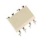
TLP222A-2 4 1 8
Unit: mm
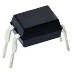
TLP222A
Pin Configuration (top view)
TLP222A 1
― ― 11-5B2
TOSHIBA
Weight: 0.26 g (typ.)
TLP222A-2
2 2 3 3 1: Anode 2: Cathode 3: Drain 4: Drain 6 7
4
5
1, 3 2, 4 5 6 7 8
: Anode : Cathode : Drain D1 : Drain D2 : Drain D3 : Drain D4
JEDEC JEITA TOSHIBA
― ― 11-10C4
Weight: 0.54 g (typ.)
1
2007-10-01
�TLP222A,TLP222A-2
Absolute Maximum Rating (Ta = 25°C)
Characteristics Forward current Forward current derating (Ta > 25°C) = LED Peak forward current Reverse voltage Junction temperature Off-state output terminal voltage TLP222A On-state current One channel operation Two channel operations Symbol IF ΔIF/°C IFP VR Tj VOFF Rating 50 −0.5 1 5 125 60 Unit mA mA/°C A V °C V
TLP222A-2
ION
500
mA
Detector
TLP222A One Forward channel current operation derating TLP222A-2 > 25°C) (Ta = Two channel operations Junction temperature
ΔION/°C
−5.0
mA/°C
Tj Tstg Topr Tsol BVS
125 −55 to 125 −40 to 85 260 2500
°C °C °C °C Vrms
Storage temperature Operating temperature Lead soldering temperature (10 s) Isolation voltage (AC, 1 min, R.H. < 60%) = (Note 1)
Note: Using continuously under heavy loads (e.g. the application of high temperature/current/voltage and the significant change in temperature, etc.) may cause this product to decrease in the reliability significantly even if the operating conditions (i.e. operating temperature/current/voltage, etc.) are within the absolute maximum ratings. Please design the appropriate reliability upon reviewing the Toshiba Semiconductor Reliability Handbook (“Handling Precautions”/“Derating Concept and Methods”) and individual reliability data (i.e. reliability test report and estimated failure rate, etc). Note 1: LED pins are shorted together. Detector pins are also shorted together.
Recommended Operating Conditions
Characteristics Supply voltage Forward current On-state current Operating temperature Symbol VDD IF ION Topr Min ⎯ 5 ⎯ −20 Typ. ⎯ 7.5 ⎯ ⎯ Max 48 25 500 65 Unit V mA mA °C
Note: Recommended operating conditions are given as a design guideline to obtain expected performance of the device. Additionally, each item is an independent guideline respectively. In developing designs using this product, please confirm specified characteristics shown in this document.
Electrical Characteristics (Ta = 25°C)
Characteristics Forward voltage LED Reverse current Capacitance Detector Off-state current Capacitance Symbol VF IR CT IOFF COFF Test Condition IF = 10 mA VR = 5 V V = 0, f = 1 MHz VOFF = 60 V V = 0, f = 1 MHz Min 1.0 ⎯ ⎯ ⎯ ⎯ Typ. 1.15 ⎯ 30 ⎯ 130 Max 1.3 10 ⎯ 1 ⎯ Unit V μA pF μA pF
2
2007-10-01
�TLP222A,TLP222A-2
Coupled Electrical Characteristics (Ta = 25°C)
Characteristics Trigger LED current Return LED current On-state resistance Symbol IFT IFC RON Test Condition ION = 500 mA IOFF = 100 μA ION = 500 mA, IF= 5 mA Min ⎯ 0.1 ⎯ Typ. 1.6 ⎯ 1 Max 3 ⎯ 2 Unit mA mA Ω
Isolation Characteristics (Ta = 25°C)
Characteristics Capacitance input to output Isolation resistance Symbol CS RS Test Condition VS = 0 V, f = 1 MHz VS = 500 V, R.H. < 60% = AC, 1 min Isolation voltage BVS AC, 1 s, in oil DC, 1 min, in oil Min ⎯ 5 × 10
10
Typ. 0.8 10
14
Max ⎯ ⎯ ⎯ ⎯ ⎯
Unit pF Ω Vrms Vdc
2500 ⎯ ⎯
⎯ 5000 5000
Switching Characteristics (Ta = 25°C)
Characteristics Turn-on time Turn-off time Symbol tON tOFF Test Condition RL = 200 Ω VDD = 20 V, IF = 5 mA Min ⎯ (Note 2) ⎯ Typ. 0.8 0.1 Max 2 0.5 Unit ms
Note 2: Switching time test circuit
IF TLP222A 1 4 RL VDD IF VOUT 2 3 VOUT 10% tON 90% tOFF
IF
TLP222A-2 1 8 RL
VDD
VOUT 2 7
3
2007-10-01
�TLP222A,TLP222A-2
IF – Ta
100 600
ION – Ta
IF (mA)
ION (mA) On-sate current
0 20 40 60 80 100 120
80
500
Allowable forward current
400
60
300
40
200
20
100
0 −20
0 −20
0
20
40
60
80
100
120
Ambient temperature Ta (°C)
Ambient temperature Ta (°C)
IF – V F
100 Ta = 25°C 600 Ta = 25°C IF = 5 m A
ION – VON
10
On-state current ION (mA)
30
400
(mA)
Forward current IF
200
3
0
1
−200
0.3
−400
0.1 0.6
0.8
1
1.2
1.4
1.6
1.8
−600 −0.6
−0.4
−0.2
0
0.2
0.4
0.6
Forward voltage VF
(V)
On-state voltage VON (V)
RON – Ta
5 ION = 500 mA IF = 5 m A 4 5 ION = 500 mA t
很抱歉,暂时无法提供与“TLP222A-2”相匹配的价格&库存,您可以联系我们找货
免费人工找货- 国内价格
- 1+38.31559
- 10+36.89649
- 100+33.49066
- 500+31.78775