PANDRIVE™
PANdrive™ for Stepper
PD42-1070 Hardware Manual
Hardware Version V1.00 | Document Revision V1.20 • 2019-01-24
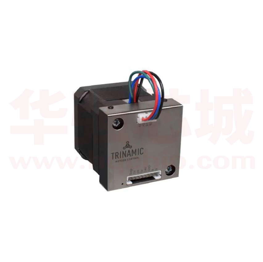
PD42-1070 is an easy to use PANdrive™ smart stepper motor. The module is controlled via a step
and direction interface. One configuration pin selects the current control mode between stealthChop™ for absolute silent motor control and spreadCycle™ for high speed. A TTL UART interface
allows for more advanced configuration, for example of the stallGuard2™ and coolStep™ features,
and permanent parameter storage via TMCL™-IDE.
Features
•
•
•
•
•
•
•
•
Applications
• Lab-Automation
• Manufacturing
• Robotics
• Factory Automation
Supply Voltage +9 to +24V DC
Step and direction interface
microPlyer™ to 256 µ-steps
stealthChop™ silent PWM mode
spreadCycle™ smart mixed decay
stallGuard2™ load detection
coolStep™ autom. current scaling
UART configuration interface
• CNC
• Laboratory Automation
Simplified Block Diagram
9...24V
UART
TMCL
Memory
SPI
µC
SPI
cDriver
with
stealthChop
STEP/DIR
EN
CHOP
©2019 TRINAMIC Motion Control GmbH & Co. KG, Hamburg, Germany
Terms of delivery and rights to technical change reserved.
Download newest version at: www.trinamic.com
Read entire documentation.
Step
Motor
�2 / 25
PD42-1070 Hardware Manual • Hardware Version V1.00 | Document Revision V1.20 • 2019-01-24
Contents
1 Features
1.1 General Features . . . . . . .
1.2 TRINAMIC’s Unique Features
1.2.1 stealthChop™ . . . . .
1.2.2 spreadCycle™ . . . . .
1.3 stallGuard2 . . . . . . . . . . .
1.4 coolStep . . . . . . . . . . . .
.
.
.
.
.
.
.
.
.
.
.
.
.
.
.
.
.
.
.
.
.
.
.
.
.
.
.
.
.
.
.
.
.
.
.
.
.
.
.
.
.
.
.
.
.
.
.
.
.
.
.
.
.
.
.
.
.
.
.
.
.
.
.
.
.
.
.
.
.
.
.
.
.
.
.
.
.
.
.
.
.
.
.
.
.
.
.
.
.
.
.
.
.
.
.
.
.
.
.
.
.
.
.
.
.
.
.
.
.
.
.
.
.
.
.
.
.
.
.
.
.
.
.
.
.
.
.
.
.
.
.
.
.
.
.
.
.
.
.
.
.
.
.
.
.
.
.
.
.
.
.
.
.
.
.
.
.
.
.
.
.
.
.
.
.
.
.
.
.
.
.
.
.
.
.
.
.
.
.
.
.
.
.
.
.
.
.
.
.
.
.
.
.
.
.
.
.
.
.
.
.
.
.
.
.
.
.
.
.
.
.
.
.
.
.
.
.
.
.
.
.
.
.
.
.
.
.
.
3
3
4
4
4
5
5
2 Order Codes
6
3 Mechanical and Electrical Interfacing
3.1 PD42-1070 Dimensions and Weight . . . . . . . . . . . . . . . . . . . . . . . . . . . . . . . . . .
3.2 PD42-1070 Motor Parameters . . . . . . . . . . . . . . . . . . . . . . . . . . . . . . . . . . . . .
3.3 PD42-1070 Torque Curves . . . . . . . . . . . . . . . . . . . . . . . . . . . . . . . . . . . . . . . .
7
7
8
9
4 Connectors and LEDs
4.1 Motor Connector . . .
4.2 I/O Connector . . . . .
4.3 TTL UART Connection
4.4 Status LEDs . . . . . .
.
.
.
.
.
.
.
.
.
.
.
.
.
.
.
.
.
.
.
.
.
.
.
.
.
.
.
.
.
.
.
.
.
.
.
.
.
.
.
.
.
.
.
.
.
.
.
.
.
.
.
.
.
.
.
.
.
.
.
.
.
.
.
.
.
.
.
.
.
.
.
.
.
.
.
.
.
.
.
.
.
.
.
.
.
.
.
.
.
.
.
.
.
.
.
.
.
.
.
.
.
.
.
.
.
.
.
.
.
.
.
.
.
.
.
.
.
.
.
.
.
.
.
.
.
.
.
.
.
.
.
.
.
.
.
.
.
.
.
.
.
.
.
.
.
.
.
.
.
.
.
.
.
.
.
.
.
.
.
.
.
.
.
.
.
.
.
.
11
11
12
13
13
5 Functional Description
5.1 Typical Application Wiring . . . . . . . . . . . . . . . . .
5.2 Optically Isolated Inputs with Common Anode Input .
5.3 Optically Isolated Inputs with Common Cathode Input
5.4 Thermal Behavior . . . . . . . . . . . . . . . . . . . . . .
.
.
.
.
.
.
.
.
.
.
.
.
.
.
.
.
.
.
.
.
.
.
.
.
.
.
.
.
.
.
.
.
.
.
.
.
.
.
.
.
.
.
.
.
.
.
.
.
.
.
.
.
.
.
.
.
.
.
.
.
.
.
.
.
.
.
.
.
.
.
.
.
.
.
.
.
.
.
.
.
.
.
.
.
.
.
.
.
.
.
.
.
14
14
14
16
17
6 Operational Ratings and Characteristics
6.1 Absolute Maximum Ratings . . . . . . . . . . . . . . . .
6.2 Electrical Characteristics (Ambient Temperature 25° C)
6.3 I/O Ratings (Ambient Temperature 25° C) . . . . . . . .
6.4 Functional Characteristics . . . . . . . . . . . . . . . . .
6.5 Other Requirements . . . . . . . . . . . . . . . . . . . .
.
.
.
.
.
.
.
.
.
.
.
.
.
.
.
.
.
.
.
.
.
.
.
.
.
.
.
.
.
.
.
.
.
.
.
.
.
.
.
.
.
.
.
.
.
.
.
.
.
.
.
.
.
.
.
.
.
.
.
.
.
.
.
.
.
.
.
.
.
.
.
.
.
.
.
.
.
.
.
.
.
.
.
.
.
.
.
.
.
.
.
.
.
.
.
.
.
.
.
.
.
.
.
.
.
.
.
.
.
.
.
.
.
.
.
18
18
18
18
19
19
7 Abbreviations used in this Manual
20
8 Figures Index
21
9 Tables Index
22
10 Supplemental Directives
10.1 Producer Information . . . . . . . . .
10.2 Copyright . . . . . . . . . . . . . . . . .
10.3 Trademark Designations and Symbols
10.4 Target User . . . . . . . . . . . . . . . .
10.5 Disclaimer: Life Support Systems . . .
10.6 Disclaimer: Intended Use . . . . . . .
10.7 Collateral Documents & Tools . . . . .
.
.
.
.
.
.
.
.
.
.
.
.
.
.
.
.
.
.
.
.
.
.
.
.
.
.
.
.
.
.
.
.
.
.
.
.
.
.
.
.
.
.
.
.
.
.
.
.
.
.
.
.
.
.
.
.
.
.
.
.
.
.
.
.
.
.
.
.
.
.
.
.
.
.
.
.
.
.
.
.
.
.
.
.
.
.
.
.
.
.
.
.
.
.
.
.
.
.
.
.
.
.
.
.
.
.
.
.
.
.
.
.
.
.
.
.
.
.
.
.
.
.
.
.
.
.
.
.
.
.
.
.
.
.
.
.
.
.
.
.
.
.
.
.
.
.
.
.
.
.
.
.
.
.
.
.
.
.
.
.
.
.
.
.
.
.
.
.
.
.
.
.
.
.
.
.
.
.
.
.
.
.
.
.
.
.
.
.
.
.
.
.
.
.
.
.
.
.
.
.
.
.
.
.
.
.
.
.
.
.
.
.
.
.
.
.
.
.
.
.
.
.
.
.
.
.
.
.
.
.
.
23
23
23
23
23
23
23
24
11 Revision History
25
11.1 Hardware Revision . . . . . . . . . . . . . . . . . . . . . . . . . . . . . . . . . . . . . . . . . . . . 25
11.2 Document Revision . . . . . . . . . . . . . . . . . . . . . . . . . . . . . . . . . . . . . . . . . . . . 25
©2019 TRINAMIC Motion Control GmbH & Co. KG, Hamburg, Germany
Terms of delivery and rights to technical change reserved.
Download newest version at www.trinamic.com
�PD42-1070 Hardware Manual • Hardware Version V1.00 | Document Revision V1.20 • 2019-01-24
1
3 / 25
Features
The PANdrive™ PD42-1070 is a full mechatronic solution with state of the art feature set. It is highly
integrated and offers a convenient handling.
The PD42-1070 includes a stepper motor and driver electronics. It can be used in many decentralized
applications and has been designed for 0.20...0.47 Nm max. holding torque and 24V DC nominal supply
voltage. With stealthChop™, the PD42-1070 offers absolutely silent and smooth motor operation for
lower and medium velocities. With spreadCycle™, the PD42-1070 offers a high performance current
controlled chopper mode for highest velocities with perfect zero crossing performance. With stallGuard2™,
a sensorless load detection feature is provided, which is required for using the automatic current scaling
feature coolStep™. The PD42-1070 can be used with a simple step and direction interface and can be
configured using a TTL UART interface.
stallGuard2 and coolStep must be configured via TTL UART interface and are disabled by default.
1.1
General Features
Main Characteristics
• Supply Voltage +9V to +24V DC
• 1.0A RMS phase current (ca. 1.4A peak phase current)
• Highest micro step resolution, up to 256 micro steps per full step
• microPlyer™ microstep interpolator for obtaining increased smoothness of microstepping over a low
frequency STEP/DIR interface
• With housing and motor mounted
• Permanent onboard parameter storage
• Simple step & direction mode
• Noiseless stealthChop™ chopper mode for slow to medium velocities
• High performance spreadCycle™ chopper mode
• High-precision sensorless load measurement with stallGuard2™
• Automatic current scaling algorithm coolStep™ to save energy and keep your drive cool
Optically Isolated Inputs
• Step & direction interface with up to 45kHz input frequency
• Enable input to power-on/-off driver H-bridges
• Mode select input to switch between the two chopper modes
TTL UART Interface
• TTL-level UART interface for parameter configuration
• Interface speed 9600-115200 bps (default 9600 bps)
• TMCL-based protocol for online configuration and permanent parameter settings
• Bootloader for firmware updates
©2019 TRINAMIC Motion Control GmbH & Co. KG, Hamburg, Germany
Terms of delivery and rights to technical change reserved.
Download newest version at www.trinamic.com
�PD42-1070 Hardware Manual • Hardware Version V1.00 | Document Revision V1.20 • 2019-01-24
1.2
1.2.1
4 / 25
TRINAMIC’s Unique Features
stealthChop™
stealthChop is an extremely quiet mode of operation for low and medium velocities. It is based on a voltage
mode PWM. During standstill and at low velocities, the motor is absolutely noiseless. Thus, stealthChop
operated stepper motor applications are very suitable for indoor or home use. The motor operates
absolutely free of vibration at low velocities. With stealthChop, the motor current is applied by driving
a certain effective voltage into the coil, using a voltage mode PWM. There are no more configurations
required except for the regulation of the PWM voltage to yield the motor target current.
Figure 1: Motor coil sine wave current using stealthChop (measured with current probe)
1.2.2
spreadCycle™
The spreadCycle chopper is a high-precision, hysteresis-based, and simple to use chopper mode, which
automatically determines the optimum length for the fast-decay phase. Several parameters are available to
optimize the chopper to the application. spreadCycle offers optimal zero crossing performance compared
to other current controlled chopper algorithms and thereby allows for highest smoothness. The true target
current is powered into the motor coils.
Figure 2: spreadCycle principle
©2019 TRINAMIC Motion Control GmbH & Co. KG, Hamburg, Germany
Terms of delivery and rights to technical change reserved.
Download newest version at www.trinamic.com
�PD42-1070 Hardware Manual • Hardware Version V1.00 | Document Revision V1.20 • 2019-01-24
1.3
5 / 25
stallGuard2
stallGuard2 is a high-precision sensorless load measurement using the back EMF of the motor coils. It
can be used for stall detection as well as other uses at loads below those which stall the motor. The
stallGuard2 measurement value changes linearly over a wide range of load, velocity, and current settings.
At maximum motor load, the value reaches zero or is near zero. This is the most energy-efficient point of
operation for the motor.
stallGuard2
Load [Nm]
Initial stallGuard2 (SG) value: 100%
Max. load
stallGuard2 (SG) value: 0
Maximum load reached.
Motor close to stall.
Motor stalls
Figure 3: stallGuard2 Load Measurement as a Function of Load
1.4
coolStep
coolStep is a load-adaptive automatic current scaling based on the load measurement via stallGuard2.
coolStep adapts the required current to the load. Energy consumption can be reduced by as much as 75%.
coolStep allows substantial energy savings, especially for motors which see varying loads or operate at a
high duty cycle. Because a stepper motor application needs to work with a torque reserve of 30% to 50%,
even a constant-load application allows significant energy savings because coolStep automatically enables
torque reserve when required. Reducing power consumption keeps the system cooler, increases motor
life, and allows for cost reduction.
0,9
Efficiency with coolStep
0,8
Efficiency with 50v torque reserve
0,7
0,6
0,5
Efficiency
0,4
0,3
0,2
0,1
0
0
50
100
150
200
250
300
350
Velocity [RPM]
Figure 4: Energy Efficiency Example with coolStep
©2019 TRINAMIC Motion Control GmbH & Co. KG, Hamburg, Germany
Terms of delivery and rights to technical change reserved.
Download newest version at www.trinamic.com
�6 / 25
PD42-1070 Hardware Manual • Hardware Version V1.00 | Document Revision V1.20 • 2019-01-24
2
Order Codes
Order Code
Description
Size (LxWxH)
PD42-2-1070
PANdrive, 0.35Nm, 1.0A RMS, +24V DC, TTL UART interface,
S/D interface, Enable, Mode Select
42mm x 42mm x 50mm
Controller/Driver Module without motor, +24V DC, TTL
UART interface, S/D interface, Enable, Mode Select
42mm x 42mm x 12mm
PD42-1-1070
PD42-3-1070
TMCM-1070
PANdrive, 0.27Nm, 1.0A RMS, +24V DC, TTL UART interface,
S/D interface, Enable, Mode Select
PANdrive, 0.49Nm, 1.0A RMS, +24V DC, TTL UART interface,
S/D interface, Enable, Mode Select
42mm x 42mm x 45,5mm
42mm x 42mm x 59mm
Table 1: Order codes modules
Order Code
TMCM-1070-CABLE
Description
Cable loom for TMCM-1070. Contains:
• 1x cable loom for motor connector with 4-pin JST PH female connector
• 1x cable loom for I/O connector with 9-in JST PH female connector
PD-1070-CABLE
Cable loom for PD42-x-1070. Contains:
TMCM-KAMINO-CLIP
Self-Adhesive top hat rail mounting clip for TMCM-1070 base module (not
available with PANdrive versions PD42-x-1070)
TMCM-KAMINO-AP23
TMCM-KAMINO-AP24
• 1x cable loom for I/O connector with 9-in JST PH female connector
Aluminum adapter plate kit for mounting of TMCM-1070 base module to
NEMA23 size motors (not available with PANdrive versions PD42-x-1070)
Aluminum adapter plate kit for mounting of TMCM-1070 base module to
NEMA24 size motors (not available with PANdrive versions PD42-x-1070)
Table 2: Order codes cable loom
©2019 TRINAMIC Motion Control GmbH & Co. KG, Hamburg, Germany
Terms of delivery and rights to technical change reserved.
Download newest version at www.trinamic.com
�PD42-1070 Hardware Manual • Hardware Version V1.00 | Document Revision V1.20 • 2019-01-24
3
3.1
7 / 25
Mechanical and Electrical Interfacing
PD42-1070 Dimensions and Weight
The PD42-1070 includes the TMCM-1070 stepper motor driver module and a NEMA17 bipolar stepper
motor. Depending on the motor size the lengt varies.
42mm
42mm
L
Figure 5: PD42-1070 mechanical dimensions with motor
Order Code
L in mm
Weight in g
PD42-2-1070
50 ±1
≈ 320
PD42-1-1070
PD42-3-1070
45,5 ±1
59 ±1
≈ 260
≈ 395
Table 3: PD42-x-1070 length and weight
©2019 TRINAMIC Motion Control GmbH & Co. KG, Hamburg, Germany
Terms of delivery and rights to technical change reserved.
Download newest version at www.trinamic.com
�8 / 25
PD42-1070 Hardware Manual • Hardware Version V1.00 | Document Revision V1.20 • 2019-01-24
3.2
PD42-1070 Motor Parameters
Specifications
Parameter
Step angle
◦
Step angle accuracy
%
Ambient temperature
Max. motor temperature
Shaft radial play (450g load)
Tamb
◦
Tmotormax
◦
Shaft axial play (450g load)
C
C
mm
mm
Max radial force (20mm from front
flange)
N
Max axial force
Rated voltage
Unit
PD-1-1070
PD-2-1070
PD-3-1070
±5
-20...+50
±5
80
-20...+50
±5
0,02
80
0,02
80
0,02
1.8
0,08
28
1.0
1.0
1.0
V
5.3
Phase resistance at 20◦ C
Phase inductance (typ.)
Rcoil
Ω
5.3
Holding torque
Lcoil
Nm
0.27
mH
g cm2
kg
6.6
B
35
0.22
Table 4: PD42-1070 Motor Parameters
©2019 TRINAMIC Motion Control GmbH & Co. KG, Hamburg, Germany
Terms of delivery and rights to technical change reserved.
Download newest version at www.trinamic.com
28
10
A
M
0,08
10
IRM Srated
Weight
28
-20...+50
10
Rated phase current
Rotor inertia
0,08
1.8
N
Vrated
Insulation class
1.8
4.5
4.5
7.5
0.35
B
54
0.28
5.0
5.0
8.0
0.49
B
68
0.35
�PD42-1070 Hardware Manual • Hardware Version V1.00 | Document Revision V1.20 • 2019-01-24
3.3
PD42-1070 Torque Curves
9 / 25
The following diagrams show the torque vs. speed curves for the PD42-1-1070, the PD42-2-1070, and
the PD42-3-1070 at three different typical conditions. All measurements have been done in spreadCycle
chopper mode. The measurement conditions are:
1. V DD =+24V, ICOILRM S =1A, 1/16 microstep with interpolation to 1/256 microstep
2. V DD =+24V, ICOILRM S =1A, half stepping
3. V DD =+12V, ICOILRM S =1A, half stepping
Figure 6: PD42-1-1070 torque vs. speed
©2019 TRINAMIC Motion Control GmbH & Co. KG, Hamburg, Germany
Terms of delivery and rights to technical change reserved.
Download newest version at www.trinamic.com
�PD42-1070 Hardware Manual • Hardware Version V1.00 | Document Revision V1.20 • 2019-01-24
Figure 7: PD42-2-1070 torque vs. speed
Figure 8: PD42-3-1070 torque vs. speed
©2019 TRINAMIC Motion Control GmbH & Co. KG, Hamburg, Germany
Terms of delivery and rights to technical change reserved.
Download newest version at www.trinamic.com
10 / 25
�PD42-1070 Hardware Manual • Hardware Version V1.00 | Document Revision V1.20 • 2019-01-24
4
11 / 25
Connectors and LEDs
Figure 9: PD42-1070 connectors (pin 1 highlighted in red)
4.1
Motor Connector
Pin no.
Pin name
Description
2
A2
Motor phase A pin 2
1
3
4
A1
B1
B2
Motor phase A pin 1
Motor phase B pin 1
Motor phase B pin 2
Table 5: Motor connector pinning
NOTICE
Do not connect or disconnect motor during operation!
Motor cable and motor inductivity might lead to voltage spikes when the motor is
(dis)connected while energized. These voltage spikes might exceed voltage limits
of the driver MOSFETs and might permanently damage them. Therefore, always
switch off or disconnect power supply before (dis)connecting the motor.
©2019 TRINAMIC Motion Control GmbH & Co. KG, Hamburg, Germany
Terms of delivery and rights to technical change reserved.
Download newest version at www.trinamic.com
�PD42-1070 Hardware Manual • Hardware Version V1.00 | Document Revision V1.20 • 2019-01-24
12 / 25
4.2 I/O Connector
Pin no.
Pin name
Description
2
V+
Supply voltage (V DD) +9V to +28V DC
1
3
4
5
6
7
GND
DIR
STEP
EN
CHOP
COMM
8
RXD
9
TXD
Supply ground connection, also used for USB serial converter ground connection
Optically isolated direction input of S/D interface
Optically isolated step input of S/D interface
Optically isolated enable input of motor driver H-bridges
Optically isolated chopper mode selection input
Opto-coupler common anode or cathode, connect to ground or VCCIO (3.3V to
24V)
TTL-level UART receive line, use with USB serial converter TXD line to connect to
PC
TTL-level UART transmit line, use with USB serial converter RXD line to connect to
PC
Table 6: I/O connector pinning
NOTICE
Supply Voltage Buffering / Add External Power Supply Capacitors
A sufficiently buffered power supply or an external electrolyte capacitor
connected between V+ and GND is recommended for stable operation.
It is recommended to connect an electrolytic capacitor of significant size to the
power supply lines next to the PD42-1070.
Rule of thumb for size of electrolytic capacitor: C = 1000 µF
A ∗ ISU P P LY
The PD42-1070 comes with approximately 40µF of onboard ceramic capacitors.
NOTICE
There is no reverse polarity protection on the supply input!
The module will short any reversed supply voltage and board electronics will get
damaged.
NOTICE
Power Up Sequence
The PD42-1070 must be powered up with disabled driver stage only. Depending
on your configuration the EN input should be logically OFF. For example, if COMM
input is connected to 3.3V to 24V, the EN input must be 0V. If common ground or
0V level is connected to COMM input, the EN input must have high level.
©2019 TRINAMIC Motion Control GmbH & Co. KG, Hamburg, Germany
Terms of delivery and rights to technical change reserved.
Download newest version at www.trinamic.com
�PD42-1070 Hardware Manual • Hardware Version V1.00 | Document Revision V1.20 • 2019-01-24
4.3
13 / 25
TTL UART Connection
To connect via the TTL UART interface to a host PC, we suggest using a USB serial converter from TTL-UART
(5V) to USB interface.
Communication with the host PC, for example when using TRINAMIC’s TMCL-IDE, is done via the Virtual
COM port installed by the converter driver.
More information on the TMCL-IDE and the latest release can be found here: www.trinamic.com
The converter cable must be connected to pins 1, 8, and 9 (GND, RXD, TXD) of the I/O connector.
Note
Default Baud Rates
The default baud rate is 9600 bps.
In bootloader mode, the baud rate is 115200 bps.
USB to UART converter
For example, the TTL-232R-5V from FTDI is working with the module and has
been tested. More information on this converter is available on the FTDI website:
www.ftdichip.com
Info
5V TTL UART Level
The TTL UART interface works with 5V level. Take special care when selecting a
converter cable for USB connection.
NOTICE
4.4
Status LEDs
The PD42-1070 has one green status LED. See figure 9 for its location.
State
Description
Permanent on
Bootloader mode
Blinking
Off
Heartbeat, MCU active, normal operation
Power Off
Table 7: LED state description
©2019 TRINAMIC Motion Control GmbH & Co. KG, Hamburg, Germany
Terms of delivery and rights to technical change reserved.
Download newest version at www.trinamic.com
�PD42-1070 Hardware Manual • Hardware Version V1.00 | Document Revision V1.20 • 2019-01-24
5
14 / 25
Functional Description
5.1
Typical Application Wiring
Wire the PD42-1070 as shown in the following figures.
• Connect the the power supply to V+ and GND.
• Connect the Step and Direction signals to your motion controller.
• At power up time, the EN input must be low (= driver stage disabled)!
• Optional: Connect UART to a TTL UART interface with 5V logic levels. To configure your PD42-1070
connect start the TMCL-IDE and use the parameterization tools. For detailed instructions refer to the
PD42-1070-firmware-manual.
Note
The TTL UART interface is not optically isolated. It requires 5V level signals.
Nevertheless, it provides basic ESD and rail-to-rail signal line protection for the
PD42-1070.
Figure 10: Typical application scenario with 5V inputs
5.2
Optically Isolated Inputs with Common Anode Input
The control inputs of the PD42-1070 are optically isolated (not the TTL UART interface). All optocouplers
share one common anode (COMM) input as shown in the figure above.
©2019 TRINAMIC Motion Control GmbH & Co. KG, Hamburg, Germany
Terms of delivery and rights to technical change reserved.
Download newest version at www.trinamic.com
�PD42-1070 Hardware Manual • Hardware Version V1.00 | Document Revision V1.20 • 2019-01-24
15 / 25
Figure 11: Inputs with common anode input with 3.3V to 5V
The typical voltage at COMM input is 5V. Nevertheless, 3.3V or voltages higher than 5V can also be used as
long as the current is through the optocouplers’ emitter is between 5mA to 20mA. For 3.3V operation the
controller must be carefully selected with respect to its I/O ports, its actual output voltage, and the series
resistor of the I/O ports. The user must make sure that the current through the optocouplers’ emitter is
between 5mA to 20mA.
Note
Step pulse width
Width of the step pulses should be between 2µs and 4µs, for maximum step
frequency.
With a larger step pulse width, for example 50% duty cycle coming from a frequency generator, the maximum input frequency will be lower at ca. 9kHz..
©2019 TRINAMIC Motion Control GmbH & Co. KG, Hamburg, Germany
Terms of delivery and rights to technical change reserved.
Download newest version at www.trinamic.com
�PD42-1070 Hardware Manual • Hardware Version V1.00 | Document Revision V1.20 • 2019-01-24
16 / 25
Figure 12: Inputs with common anode input with >5V to 24V
The series resistors in the PD42-1070 are 270mOhms. For operation with voltages higher than 5V an
additional external resistor Rexternal is required per input to limit the current. See Table 8 as reference for
additional external resistor values.
COMM Voltage (V)
Value of Rexternal (Ω)
5
-
3.3
9
12
15
24
-
300
500
700
1K5
Table 8: Additional resistor reference values
Note
5.3
Rexternal Selection
Take care when selecting an additional external resistor. The resistor type must
have a fitting power rating. This depends on the voltage used at COMM input.
Optically Isolated Inputs with Common Cathode Input
The optocouplers inside PD42-1070 are bidirectional types (AC/DC). Thus, COMM can also be used as
common cathode connection.
©2019 TRINAMIC Motion Control GmbH & Co. KG, Hamburg, Germany
Terms of delivery and rights to technical change reserved.
Download newest version at www.trinamic.com
�PD42-1070 Hardware Manual • Hardware Version V1.00 | Document Revision V1.20 • 2019-01-24
5.4
17 / 25
Thermal Behavior
The default configuration parameters of the PD42-1070 are set to the specified maximum current of 1A
rms / 1.4A peak, which is the maximum motor phase current specified for the stepper motor options given
in Table 4.
Typically, at this nominal current setting the stepper motor and the driver electronics will get hot. Continuous operation at maximum current is not guaranteed without cooling the motor since the stepper driver
will switch off due to its internal over-temperature protection until temperature falls below the threshold.
Note
Operation with Maximum Current Setting
For table-top testing and application bring-up the current should be reduced or
the coolStep feature should be configured to keep heating on a reasonable level.
Especially, when there is no other cooling option for the motor.
For proper and continuous operation at maximum current, the motor flange
must be mounted to the applications mechanical interface with good contact.
©2019 TRINAMIC Motion Control GmbH & Co. KG, Hamburg, Germany
Terms of delivery and rights to technical change reserved.
Download newest version at www.trinamic.com
�18 / 25
PD42-1070 Hardware Manual • Hardware Version V1.00 | Document Revision V1.20 • 2019-01-24
6
6.1
Operational Ratings and Characteristics
Absolute Maximum Ratings
Parameter
Min
Max
Unit
Working temperature
-30
+40
°C
Supply voltage
+9
Motor coil current / sine wave peak
+28
1.4
Continuous motor current (RMS)
NOTICE
1.0
V
A
A
Avoid exceeding the absolute maximum rating under all circumstances.
Stresses above those listed under "‘Absolute Maximum Ratings"’ may cause
permanent damage to the device. This is a stress rating only and functional
operation of the device at those or any other conditions above those indicated in
the operation listings of this specification is not implied. Exposure to maximum
rating conditions for extended periods may affect device reliability.
Keep the power supply voltage below the upper limit of +28V! Otherwise
the board electronics will seriously be damaged! Especially, when the selected
operating voltage is near the upper limit a regulated power supply is highly
recommended.
6.2
Electrical Characteristics (Ambient Temperature 25° C)
Parameter
Symbol
Min
Motor coil current / sine wave peak (chopper regulated, adjustable via TTL UART interface)
V DD
ICOILpeak
0
Power supply current
ICOILRM S
0
Supply voltage
Continuous motor current (RMS)
9
Typ
24
Unit
1.4
A
26
1.0
� ICOIL
IDD
Max
1.4∗ICOIL
V
A
A
Table 10: Electrical Characteristics
6.3 I/O Ratings (Ambient Temperature 25° C)
Parameter
Symbol
Input frequency of optically isolated I/Os
VCOM M
TTL UART low level voltage
VT T L_IN
COMM input voltage
TTL UART input voltage
©2019 TRINAMIC Motion Control GmbH & Co. KG, Hamburg, Germany
Terms of delivery and rights to technical change reserved.
Download newest version at www.trinamic.com
Min
3.3
fin
VT LLL
0
Typ
5
5
Max
Unit
45
kHz
+V DD
5.5
1.75
V
V
V
�19 / 25
PD42-1070 Hardware Manual • Hardware Version V1.00 | Document Revision V1.20 • 2019-01-24
TTL UART high level voltage
VT T L H
TTL UART output voltage
VT T L_OU T
3.25
5
5
V
V
Table 11: Operational ratings of optically isolated inputs and TTL UART interface
6.4
Functional Characteristics
Parameter
Control
Step Pulse Width
Communication
Driving Mode
Stepping Resolution
Description / Value
4-wire interface with Step, Direction, Enable, and Chopper Mode Switch
The step pulse width should be between 2µs and 4µs for maximum frequency.
With a larger step pulse width, for example 50% duty cycle coming from a
frequency generator, the maximum input frequency will be lower at ca. 9kHz.
2-wire TTL UART interface for configuration, 9600-115200 bps (default 57600
bps)
spreadCycle and stealthChop chopper modes (selectable with CHOP input),
adaptive automatic current reduction using stallGuard2 and coolStep
Full, 1/2, 1/4, 1/8, 1/16, 1/32, 1/64, 1/128, 1/256 step, default is 1/16 with internal
interpolation to 1/256
Table 12: Functional Characteristics
6.5
Other Requirements
Specifications
Description or Value
Working environment
Avoid dust, water, oil mist and corrosive gases, no condensation, no frosting
Cooling
Working temperature
Free air
-30° C to +40° C
Table 13: Other Requirements and Characteristics
©2019 TRINAMIC Motion Control GmbH & Co. KG, Hamburg, Germany
Terms of delivery and rights to technical change reserved.
Download newest version at www.trinamic.com
�PD42-1070 Hardware Manual • Hardware Version V1.00 | Document Revision V1.20 • 2019-01-24
7
Abbreviations used in this Manual
Abbreviation
Description
IDE
Integrated Development Environment
COMM
LED
RMS
Common Anode or common cathode
Light Emmitting Diode
Root Mean Square value
TMCL
TRINAMIC Motion Control Language
UART
Universal Asynchronous Receiver Transmitter
TTL
USB
Transistor Transistor Logic
Universal Serial Bus
Table 14: Abbreviations used in this Manual
©2019 TRINAMIC Motion Control GmbH & Co. KG, Hamburg, Germany
Terms of delivery and rights to technical change reserved.
Download newest version at www.trinamic.com
20 / 25
�PD42-1070 Hardware Manual • Hardware Version V1.00 | Document Revision V1.20 • 2019-01-24
8
1
2
3
4
5
6
Figures Index
Motor coil sine wave current using
stealthChop (measured with current
probe) . . . . . . . . . . . . . . . . . . .
4
spreadCycle principle . . . . . . . . . .
4
stallGuard2 Load Measurement as a
Function of Load . . . . . . . . . . . .
5
Energy Efficiency Example with coolStep 5
PD42-1070 mechanical dimensions
with motor . . . . . . . . . . . . . . . .
7
PD42-1-1070 torque vs. speed . . . .
9
©2019 TRINAMIC Motion Control GmbH & Co. KG, Hamburg, Germany
Terms of delivery and rights to technical change reserved.
Download newest version at www.trinamic.com
7
8
9
10
11
12
21 / 25
PD42-2-1070 torque vs. speed . . . .
PD42-3-1070 torque vs. speed . . . .
PD42-1070 connectors (pin 1 highlighted in red) . . . . . . . . . . . . . .
Typical application scenario with 5V inputs . . . . . . . . . . . . . . . . . . . .
Inputs with common anode input with
3.3V to 5V . . . . . . . . . . . . . . . .
Inputs with common anode input with
>5V to 24V . . . . . . . . . . . . . . . .
10
10
11
14
15
16
�PD42-1070 Hardware Manual • Hardware Version V1.00 | Document Revision V1.20 • 2019-01-24
9
1
2
3
4
5
6
7
8
Tables Index
Order codes modules . . . . . . . .
Order codes cable loom . . . . . . .
PD42-x-1070 length and weight . . .
PD42-1070 Motor Parameters . . .
Motor connector pinning . . . . . .
I/O connector pinning . . . . . . . .
LED state description . . . . . . . . .
Additional resistor reference values
.
.
.
.
.
.
.
.
6
6
7
8
11
12
13
16
©2019 TRINAMIC Motion Control GmbH & Co. KG, Hamburg, Germany
Terms of delivery and rights to technical change reserved.
Download newest version at www.trinamic.com
10
11
12
13
14
15
16
22 / 25
Electrical Characteristics . . . . . . . .
Operational ratings of optically isolated inputs and TTL UART interface .
Functional Characteristics . . . . . . .
Other Requirements and Characteristics
Abbreviations used in this Manual . .
Hardware Revision . . . . . . . . . . .
Document Revision . . . . . . . . . . .
18
19
19
19
20
25
25
�PD42-1070 Hardware Manual • Hardware Version V1.00 | Document Revision V1.20 • 2019-01-24
10
23 / 25
Supplemental Directives
10.1
Producer Information
10.2
Copyright
TRINAMIC owns the content of this user manual in its entirety, including but not limited to pictures, logos,
trademarks, and resources. © Copyright 2019 TRINAMIC. All rights reserved. Electronically published by
TRINAMIC, Germany.
Redistributions of source or derived format (for example, Portable Document Format or Hypertext Markup
Language) must retain the above copyright notice, and the complete Datasheet User Manual documentation of this product including associated Application Notes; and a reference to other available
product-related documentation.
10.3
Trademark Designations and Symbols
Trademark designations and symbols used in this documentation indicate that a product or feature is
owned and registered as trademark and/or patent either by TRINAMIC or by other manufacturers, whose
products are used or referred to in combination with TRINAMIC’s products and TRINAMIC’s product documentation.
This Hardware Manual is a non-commercial publication that seeks to provide concise scientific and technical
user information to the target user. Thus, trademark designations and symbols are only entered in the
Short Spec of this document that introduces the product at a quick glance. The trademark designation
/symbol is also entered when the product or feature name occurs for the first time in the document. All
trademarks and brand names used are property of their respective owners.
10.4
Target User
The documentation provided here, is for programmers and engineers only, who are equipped with the
necessary skills and have been trained to work with this type of product.
The Target User knows how to responsibly make use of this product without causing harm to himself or
others, and without causing damage to systems or devices, in which the user incorporates the product.
10.5
Disclaimer: Life Support Systems
TRINAMIC Motion Control GmbH & Co. KG does not authorize or warrant any of its products for use in life
support systems, without the specific written consent of TRINAMIC Motion Control GmbH & Co. KG.
Life support systems are equipment intended to support or sustain life, and whose failure to perform,
when properly used in accordance with instructions provided, can be reasonably expected to result in
personal injury or death.
Information given in this document is believed to be accurate and reliable. However, no responsibility
is assumed for the consequences of its use nor for any infringement of patents or other rights of third
parties which may result from its use. Specifications are subject to change without notice.
10.6
Disclaimer: Intended Use
The data specified in this user manual is intended solely for the purpose of product description. No representations or warranties, either express or implied, of merchantability, fitness for a particular purpose
©2019 TRINAMIC Motion Control GmbH & Co. KG, Hamburg, Germany
Terms of delivery and rights to technical change reserved.
Download newest version at www.trinamic.com
�PD42-1070 Hardware Manual • Hardware Version V1.00 | Document Revision V1.20 • 2019-01-24
24 / 25
or of any other nature are made hereunder with respect to information/specification or the products to
which information refers and no guarantee with respect to compliance to the intended use is given.
In particular, this also applies to the stated possible applications or areas of applications of the product.
TRINAMIC products are not designed for and must not be used in connection with any applications where
the failure of such products would reasonably be expected to result in significant personal injury or death
(safety-Critical Applications) without TRINAMIC’s specific written consent.
TRINAMIC products are not designed nor intended for use in military or aerospace applications or environments or in automotive applications unless specifically designated for such use by TRINAMIC. TRINAMIC
conveys no patent, copyright, mask work right or other trade mark right to this product. TRINAMIC assumes
no liability for any patent and/or other trade mark rights of a third party resulting from processing or
handling of the product and/or any other use of the product.
10.7
Collateral Documents & Tools
This product documentation is related and/or associated with additional tool kits, firmware and other
items, as provided on the product page at: www.trinamic.com.
©2019 TRINAMIC Motion Control GmbH & Co. KG, Hamburg, Germany
Terms of delivery and rights to technical change reserved.
Download newest version at www.trinamic.com
�PD42-1070 Hardware Manual • Hardware Version V1.00 | Document Revision V1.20 • 2019-01-24
11
11.1
25 / 25
Revision History
Hardware Revision
Version
1.00
Date
26.06.2016
Author
BS
Description
Initial release.
Table 15: Hardware Revision
11.2
Document Revision
Version
Date
Author
Description
1.10
03.07.2018
GE
Order code for PANdrive cable corrected: PD42-1070-CABLE -> PD1070-CABLE.
1.00
1.20
26.06.2016
24.01.2019
BS
GE
Initial release.
Motor parameter table 4 corrected + updated.
Table 16: Document Revision
©2019 TRINAMIC Motion Control GmbH & Co. KG, Hamburg, Germany
Terms of delivery and rights to technical change reserved.
Download newest version at www.trinamic.com
�Mouser Electronics
Authorized Distributor
Click to View Pricing, Inventory, Delivery & Lifecycle Information:
Trinamic:
PD42-2-1070 PD42-3-1070 PD42-1-1070 PD-1070-CABLE
�