MECHATRONIC DRIVE WITH STEPPER MOTOR
PANdrive
Firmware Version V4.45
TMCL™ FIRMWARE MANUAL
+
+
TMCM-1180
PD86-1180
1-Axis Stepper
Controller / Driver
5.5A RMS/ 24 or 48V DC
USB, RS232, RS485, and CAN
+
TRINAMIC Motion Control GmbH & Co. KG
Hamburg, Germany
www.trinamic.com
+
�TMCM-1180 and PD86-1180 TMCL Firmware V4.45 Manual (Rev. 1.10 / 2014-MAY-16)
Table of Contents
1
2
3
Features ........................................................................................................................................................................... 4
Overview ......................................................................................................................................................................... 5
Putting the PD86-1180 into Operation ................................................................................................................... 6
3.1
Starting up ............................................................................................................................................................. 6
3.2
Testing with a Simple TMCL Program ........................................................................................................... 9
3.3
Operating the Module in Direct Mode......................................................................................................... 10
4
TMCL and TMCL-IDE ................................................................................................................................................... 11
4.1
Binary Command Format ................................................................................................................................ 11
4.2
Reply Format ....................................................................................................................................................... 12
4.2.1 Status Codes ................................................................................................................................................. 13
4.3
Standalone Applications .................................................................................................................................. 13
4.4
TMCL Command Overview .............................................................................................................................. 14
4.4.1 TMCL Commands ......................................................................................................................................... 14
4.4.2 Commands Listed According to Subject Area .................................................................................... 15
4.5
The ASCII Interface ........................................................................................................................................... 19
4.5.1 Format of the Command Line ................................................................................................................. 19
4.5.2 Format of a Reply........................................................................................................................................ 19
4.5.3 Configuring the ASCII Interface.............................................................................................................. 20
4.6
Commands ........................................................................................................................................................... 21
4.6.1 ROR (rotate right) ........................................................................................................................................ 21
4.6.2 ROL (rotate left)............................................................................................................................................ 22
4.6.3 MST (motor stop) ......................................................................................................................................... 23
4.6.4 MVP (move to position)............................................................................................................................. 24
4.6.5 SAP (set axis parameter) ........................................................................................................................... 26
4.6.6 GAP (get axis parameter) .......................................................................................................................... 27
4.6.7 STAP (store axis parameter) ..................................................................................................................... 28
4.6.8 RSAP (restore axis parameter) ................................................................................................................. 29
4.6.9 SGP (set global parameter)....................................................................................................................... 30
4.6.10 GGP (get global parameter) ...................................................................................................................... 31
4.6.11 STGP (store global parameter) ................................................................................................................ 32
4.6.12 RSGP (restore global parameter) ............................................................................................................ 33
4.6.13 RFS (reference search) ................................................................................................................................ 34
4.6.14 SIO (set input / output) ............................................................................................................................. 35
4.6.15 GIO (get input/output) ............................................................................................................................... 37
4.6.16 CALC (calculate) ............................................................................................................................................ 39
4.6.17 COMP (compare) ........................................................................................................................................... 40
4.6.18 JC (jump conditional) ................................................................................................................................. 41
4.6.19 JA (jump always) ......................................................................................................................................... 42
4.6.20 CSUB (call subroutine)................................................................................................................................ 43
4.6.21 RSUB (return from subroutine) ................................................................................................................ 44
4.6.22 WAIT (wait for an event to occur) ......................................................................................................... 45
4.6.23 STOP (stop TMCL program execution) ................................................................................................... 46
4.6.24 SCO (set coordinate) ................................................................................................................................... 47
4.6.25 GCO (get coordinate) .................................................................................................................................. 48
4.6.26 CCO (capture coordinate) .......................................................................................................................... 49
4.6.27 ACO (accu to coordinate; valid from TMCL version 4.18 on) .......................................................... 50
4.6.28 CALCX (calculate using the X register) .................................................................................................. 51
4.6.29 AAP (accumulator to axis parameter) .................................................................................................... 52
4.6.30 AGP (accumulator to global parameter) ............................................................................................... 53
4.6.31 CLE (clear error flags) ................................................................................................................................. 54
4.6.32 VECT (set interrupt vector) ........................................................................................................................ 55
4.6.33 EI (enable interrupt) ................................................................................................................................... 56
4.6.34 DI (disable interrupt) .................................................................................................................................. 57
4.6.35 RETI (return from interrupt) ..................................................................................................................... 58
4.6.36 Customer Specific TMCL Command Extension (UF0… UF7 / User Function) ............................... 58
4.6.37 Request Target Position Reached Event ............................................................................................... 59
www.trinamic.com
2
�TMCM-1180 and PD86-1180 TMCL Firmware V4.45 Manual (Rev. 1.10 / 2014-MAY-16)
4.6.38 BIN (return to binary mode) .................................................................................................................... 59
4.6.39 TMCL Control Functions ............................................................................................................................. 60
5
Axis Parameters .......................................................................................................................................................... 62
5.1
coolStep Related Parameters ......................................................................................................................... 68
6
Global Parameters ...................................................................................................................................................... 70
6.1
Bank 0 ................................................................................................................................................................... 70
6.2
Bank 1 ................................................................................................................................................................... 72
6.3
Bank 2 ................................................................................................................................................................... 73
6.4
Bank 3 ................................................................................................................................................................... 73
7
Hints and Tips ............................................................................................................................................................. 74
7.1
Reference Search................................................................................................................................................ 74
7.2
Changing the Prescaler Value of an Encoder ............................................................................................ 75
7.3
stallGuard2 ........................................................................................................................................................... 76
7.4
Using the RS485 interface ............................................................................................................................... 76
8
TMCL Programming Techniques and Structure ................................................................................................. 77
8.1
Initialization ........................................................................................................................................................ 77
8.2
Main Loop ............................................................................................................................................................ 77
8.3
Using Symbolic Constants .............................................................................................................................. 77
8.4
Using Variables................................................................................................................................................... 78
8.5
Using Subroutines ............................................................................................................................................. 78
8.6
Mixing Direct Mode and Standalone Mode ................................................................................................ 79
9
Life Support Policy ..................................................................................................................................................... 80
10 Revision History .......................................................................................................................................................... 81
10.1 Firmware Revision............................................................................................................................................. 81
10.2 Document Revision ........................................................................................................................................... 81
11 References .................................................................................................................................................................... 82
www.trinamic.com
3
�TMCM-1180 and PD86-1180 TMCL Firmware V4.45 Manual (Rev. 1.10 / 2014-MAY-16)
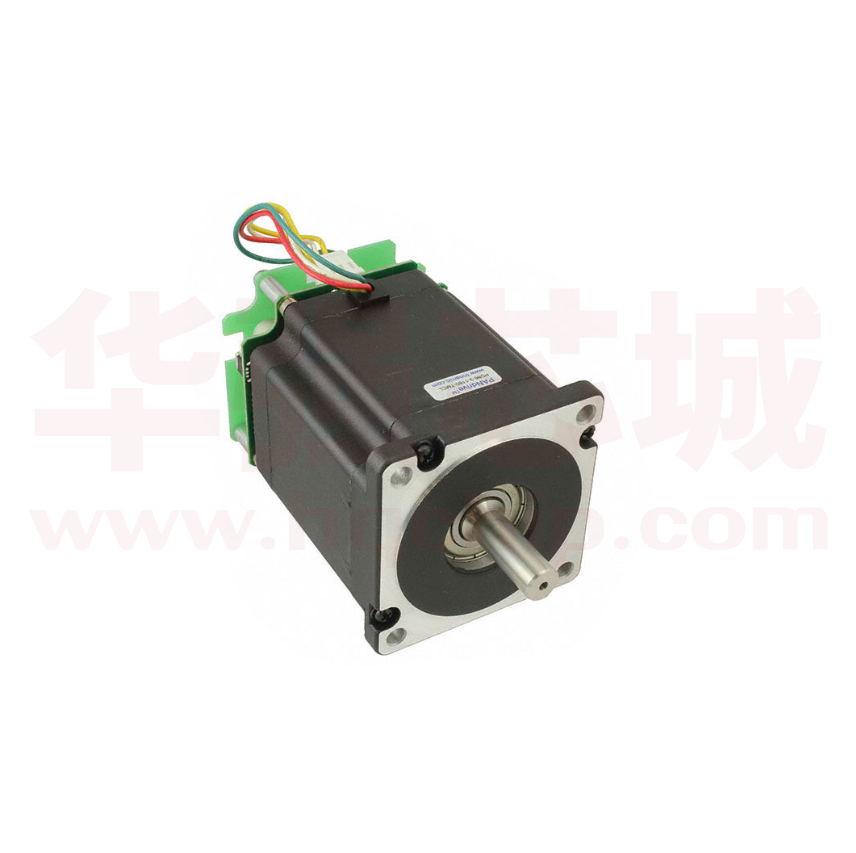
1 Features
The PD86-1180 is a full mechatronic solution with state of the arte feature set. It is highly integrated and
offers a convenient handling. The PD86-1180 consists of a NEMA 34 (flange size 86mm) stepper motor,
controller/driver electronics and integrated encoder.
The TMCM-1180 is an intelligent stepper motor controller/driver module featuring the new outstanding
coolStep™ technology for sensorless load dependent current control. This allows energy efficient motor
operation. With the advanced stallGuard2™ feature the load of the motor can be detected with high
resolution. The module is designed to be mounted directly on an 86mm flange QMot stepper motor.
Electrical data
Supply voltage: +24V DC or +48V DC nominal
Motor current: up to 5.5A RMS (programmable)
PANdrive motor
Two phase bipolar stepper motor with up to 5.5A RMS nom. coil current
Holding torque: 7Nm
Encoder
Integrated sensOstep™ magnetic encoder (max. 256 increments per rotation) e.g. for step-loss
detection under all operating conditions and positioning
Integrated motion controller
Motion profile calculation in real-time (TMC428/429 motion controller)
On the fly alteration of motor parameters (e.g. position, velocity, acceleration)
High performance microcontroller for overall system control and serial communication protocol
handling
Bipolar stepper motor driver
Up to 256 microsteps per full step
High-efficient operation, low power dissipation
Dynamic current control
Integrated protection
stallGuard2 feature for stall detection
coolStep feature for reduced power consumption and heat dissipation
Interfaces
inputs for stop switches (left and right) and home switch
general purpose inputs and 2 general purpose outputs
USB, RS232, RS485 and CAN (2.0B up to 1Mbit/s) communication interfaces
Safety features
Shutdown input. The driver will be disabled in hardware as long as this pin is left open or shorted
to ground
Separate supply voltage inputs for driver and digital logic – driver supply voltage may be switched
off externally while supply for digital logic and therefore digital logic remains active
Software
Available with TMCL or CANopen
Standalone TMCL operation or remote controlled operation
Program memory (non volatile) for up to 2048 TMCL commands
PC-based application development software TMCL-IDE available for free
CANopen: CiA 301 + CiA 402 (homing mode, profile position mode and velocity mode) supported
Please refer to separate Hardware Manual for further information.
www.trinamic.com
4
�TMCM-1180 and PD86-1180 TMCL Firmware V4.45 Manual (Rev. 1.10 / 2014-MAY-16)
2 Overview
As with most TRINAMIC modules the software running on the microprocessor of the TMCM-1180 consists
of two parts, a boot loader and the firmware itself. Whereas the boot loader is installed during
production and testing at TRINAMIC and remains normally untouched throughout the whole lifetime, the
firmware can be updated by the user. New versions can be downloaded free of charge from the
TRINAMIC website (http://www.trinamic.com).
The firmware shipped with this module is related to the standard TMCL firmware shipped with most of
TRINAMIC modules with regard to protocol and commands. Corresponding, this module is based on the
TMC428/429 stepper motor controller and the TMC262A-PC power driver and supports the standard TMCL
with a special range of values.
The TMC262A-PC is a new energy efficient high current high precision microstepping driver IC for bipolar
stepper motors and offers TRINAMICs patented coolStep feature with its special commands. Please mind
this technical innovation.
All commands and parameters available with this unit are explained on the following pages.
www.trinamic.com
5
�TMCM-1180 and PD86-1180 TMCL Firmware V4.45 Manual (Rev. 1.10 / 2014-MAY-16)
3 Putting the PD86-1180 into Operation
Here you can find basic information for putting your PANdrive into operation. The further text contains a
simple example for a TMCL program and a short description of operating the module in direct mode.
The things you need:
-
PD83-1180
Interface (RS232, RS485, USB or CAN) suitable to your PANdrive with cables
Nominal supply voltage +24V DC (+24 or +48V DC) for your module
TMCL-IDE program and PC
External encoder optional. The PANdrive™ has an integrated sensOstep encoder.
Precautions:
-
Do not connect or disconnect the PD86-1180 while powered!
Do not connect or disconnect the motor while powered!
Do not exceed the maximum power supply of 55V DC.
Start with power supply OFF!
3.1 Starting up
Encoder Step/Dir Input Output
1
1
1
1
Serial
communication
1
Power
USB
1
1
Motor
Figure 3.1 Overview connectors
www.trinamic.com
6
�TMCM-1180 and PD86-1180 TMCL Firmware V4.45 Manual (Rev. 1.10 / 2014-MAY-16)
1.
Connect the interface
a) Connect the RS232, the RS485, or the CAN interface
A 2mm pitch 8 pin JST B8B-PH-K connector is used for serial communication. With this connector
the module supports RS232, RS485, and CAN communication.
Pi
n
1
2
1
8
3
4
5
6
7
8
Label
Description
RS232_Tx
D
RS232_Rx
D
GND
CAN_H
CAN_L
GND
RS485+
RS485-
RS232 transmit data
RS232 receive data
Module ground (system and signal ground)
CAN_H bus line (dominant high)
CAN_L bus line (dominant low)
Module ground (system and signal ground)
RS485 non-inverted bus signal
RS485 inverted bus signal
Figure 3.2: RS232, RS485, and CAN connector
b) Connect the USB interface
A 5-pin mini-USB connector is available on the board.
Download and install the file TMCM-1180.inf (www.trinamic.com).
1
2.
5
Label
VBUS
DD+
ID
GND
Description
+5V power
Data –
Data +
Not connected
ground
Connect the power supply
A 4-pin JST B04P-VL connector is used for power supply.
1
3.
Pin
1
2
3
4
5
4
Pin
Label
Description
Module + driver stage power supply input
(nom. +48V DC)
(Optional) separate digital logic power supply input
(nom. +48V DC)
1
+UDriver
2
+ULogic
3
GND
Module ground (power supply and signal ground)
4
GND
Module ground (power supply and signal ground)
Switch ON the power supply
The LED for power should glow now. This indicates that the on-board +5V supply is available.
If this does not occur, switch power OFF and check your connections as well as the power
supply.
www.trinamic.com
7
�TMCM-1180 and PD86-1180 TMCL Firmware V4.45 Manual (Rev. 1.10 / 2014-MAY-16)
4.
Start the TMCL-IDE software development environment
The TMCL-IDE is available on the TechLibCD and on www.trinamic.com.
Installing the TMCL-IDE:
-
Make sure the COM port you intend to use is not blocked by another program.
Open TMCL-IDE by clicking TMCL.exe.
Choose Setup and Options and thereafter the Connection tab.
-
For RS232 and RS485 choose COM port and type with the parameters shown below
(baud rate 9600). Click OK.
Please refer to the TMCL-IDE User Manual for more information about connecting the other interfaces (see
www.TRINAMIC.com).
www.trinamic.com
8
�TMCM-1180 and PD86-1180 TMCL Firmware V4.45 Manual (Rev. 1.10 / 2014-MAY-16)
3.2 Testing with a Simple TMCL Program
Open the file test2.tmc. Change the motor number 2 in the second paragraph in motor number 0
(because there is only one motor involved). Now your test program looks as follows:
//A simple example for using TMCL and TMCL-IDE
ROL 0, 500
WAIT TICKS, 0, 500
MST 0
ROR 0, 250
WAIT TICKS, 0, 500
MST 0
Loop:
1.
2.
3.
4.
SAP 4, 0, 500
SAP 5, 0, 50
MVP ABS, 0, 10000
WAIT POS, 0, 0
MVP ABS, 0, -10000
WAIT POS, 0, 0
JA Loop
//Rotate motor 0 with speed 500
//Rotate motor 0 with 250
//Set max. Velocity
//Set max. Acceleration
//Move to Position 10000
//Wait until position reached
//Move to Position -10000
//Wait until position reached
//Infinite Loop
Click on Icon Assemble to convert the TMCL into machine code.
Then download the program to the TMCM-1180 module via the icon Download.
Press icon Run. The desired program will be executed.
Click Stop button to stop the program.
www.trinamic.com
9
�TMCM-1180 and PD86-1180 TMCL Firmware V4.45 Manual (Rev. 1.10 / 2014-MAY-16)
10
3.3 Operating the Module in Direct Mode
1.
Start TMCL Direct Mode.
2.
If the communication is established the PD86-1180 is automatically detected. If the module is
not detected, please check all points above (cables, interface, power supply, COM port, baud
rate).
Issue a command by choosing Instruction, Type (if necessary), Motor, and Value and click
Execute to send it to the module.
3.
Examples:
ROR rotate right, motor 0, value 100
MST motor stop, motor 0
-> Click Execute. The first motor is rotating now.
-> Click Execute. The first motor stops now.
Note
Chapter 5 (axis parameters) includes a diagram which shows important coolStep related axis parameters
and their functions.
www.trinamic.com
�TMCM-1180 and PD86-1180 TMCL Firmware V4.45 Manual (Rev. 1.10 / 2014-MAY-16)
11
4 TMCL and TMCL-IDE
The TMCM-1180 supports TMCL direct mode (binary commands or ASCII interface) and standalone TMCL
program execution. You can store up to 2048 TMCL instructions on it.
In direct mode and most cases the TMCL communication over RS485, RS232, USB or CAN follows a strict
master/slave relationship. That is, a host computer (e.g. PC/PLC) acting as the interface bus master will
send a command to the TMCL-1180. The TMCL interpreter on the module will then interpret this
command, do the initialization of the motion controller, read inputs and write outputs or whatever is
necessary according to the specified command. As soon as this step has been done, the module will
send a reply back over RS485/RS232/USB/CAN to the bus master. Only then should the master transfer the
next command. Normally, the module will just switch to transmission and occupy the bus for a reply,
otherwise it will stay in receive mode. It will not send any data over the interface without receiving a
command first. This way, any collision on the bus will be avoided when there are more than two nodes
connected to a single bus.
The Trinamic Motion Control Language [TMCL] provides a set of structured motion control commands.
Every motion control command can be given by a host computer or can be stored in an EEPROM on the
TMCM module to form programs that run standalone on the module. For this purpose there are not only
motion control commands but also commands to control the program structure (like conditional jumps,
compare and calculating).
Every command has a binary representation and a mnemonic. The binary format is used to send
commands from the host to a module in direct mode, whereas the mnemonic format is used for easy
usage of the commands when developing standalone TMCL applications using the TMCL-IDE (IDE means
Integrated Development Environment).
There is also a set of configuration variables for the axis and for global parameters which allow
individual configuration of nearly every function of a module. This manual gives a detailed description of
all TMCL commands and their usage.
4.1 Binary Command Format
Every command has a mnemonic and a binary representation. When commands are sent from a host to a
module, the binary format has to be used. Every command consists of a one-byte command field, a onebyte type field, a one-byte motor/bank field and a four-byte value field. So the binary representation of a
command always has seven bytes. When a command is to be sent via RS232, RS485 or USB interface, it
has to be enclosed by an address byte at the beginning and a checksum byte at the end. In this case it
consists of nine bytes.
This is different when communicating is via the CAN bus. Address and checksum are included in the CAN
standard and do not have to be supplied by the user.
The binary command format for RS232/RS485/USB is as follows:
Bytes
1
1
1
1
4
1
Meaning
Module address
Command number
Type number
Motor or Bank number
Value (MSB first!)
Checksum
The checksum is calculated by adding up all the other bytes using an 8-bit addition.
When using CAN bus, just leave out the first byte (module address) and the last byte (checksum).
www.trinamic.com
�TMCM-1180 and PD86-1180 TMCL Firmware V4.45 Manual (Rev. 1.10 / 2014-MAY-16)
12
CHECKSUM CALCULATION
As mentioned above, the checksum is calculated by adding up all bytes (including the module address
byte) using 8-bit addition. Here are two examples to show how to do this:
in C:
unsigned char i, Checksum;
unsigned char Command[9];
//Set the “Command” array to the desired command
Checksum = Command[0];
for(i=1; i×
1
2
3
𝐼𝐼𝑅𝑅𝑅𝑅𝑅𝑅 =< 𝑣𝑣𝑣𝑣𝑣𝑣𝑣𝑣𝑣𝑣 >×
search left stop switch only
1… 3
search right
stop switch, then search
left stop switch
search right stop switch, then search
left stop switch from both sides
RW
RW
255
6.6𝐴𝐴
255
RWE
Adding 128 to these values reverses the
polarity of the home switch input.
194
Reference search
speed
195
Reference switch Similar to parameter no. 194, the speed for 0… 2047
the switching point calibration can be
speed
selected.
Reference switch This parameter provides the distance between 0… 2.147.483.647
the end switches after executing the RFS
distance
command (mode 2 or 3).
Boost current
Current used for acceleration and deceleration 0… 255
9.3𝐴𝐴
phases.
𝐼𝐼𝑝𝑝𝑝𝑝𝑝𝑝𝑝𝑝 =< 𝑣𝑣𝑣𝑣𝑣𝑣𝑣𝑣𝑣𝑣 >×
255
If set to 0 the same current as set by axis
6.6𝐴𝐴
parameter 6 will be used.
𝐼𝐼𝑅𝑅𝑅𝑅𝑅𝑅 =< 𝑣𝑣𝑣𝑣𝑣𝑣𝑣𝑣𝑣𝑣 >×
196
200
For the reference search this value directly 0… 2047
specifies the search speed.
RWE
255
www.trinamic.com
RWE
R
RWE
�TMCM-1180 and PD86-1180 TMCL Firmware V4.45 Manual (Rev. 1.10 / 2014-MAY-16)
Number
204
Axis Parameter
Freewheeling
206
Actual load
value
TMC262 driver
error flags
208
Description
Time after which the power to the motor
will be cut when its velocity has reached
zero.
Readout of the actual load value with used
for stall detection (stallGuard2).
Bit 0
Bit 1
Bit 2
Bit 3
Bit 4
Bit 5
Bit 6
Bit 7
209
Encoder position
210
Encoder
prescaler
212
Maximum
encoder
deviation
214
Power down
delay
215
Absolute
encoder value
Step/Dir mode
254
Acc.
RWE
0/1
R
R
RW
When the actual position (parameter 1) and
the encoder position (parameter 209) differ
more than set here the motor will be
stopped. This function is switched off when
the maximum deviation is set to zero.
Standstill period before the current is changed
down to standby current. The standard value
is 200 (value equates 2000msec).
Absolute value of the encoder.
RWE
1
3
4
5
www.trinamic.com
Range [Unit]
0… 65535
0 = never
[msec]
0… 1023
The value of an encoder register can be read [encoder steps]
out or written.
Prescaler for the sensOstep encoder.
See paragraph 7.1
2
* Unit of acceleration:
stallGuard2 status
(1: threshold reached)
Overtemperature
(1: driver is shut down due to
overtemperature)
Pre-warning overtemperature
(1: Threshold is exceeded)
Short to ground A
(1: Short condition detected,
driver
currently shut down)
Short to ground B
(1: Short condition detected, driver currently
shut down)
Open load A
(1: no chopper event has happened during
the last period with constant coil polarity)
Open load B
(1: no chopper event has happened during
the last period with constant coil polarity)
Stand still
(1: No step impulse occurred on the step
input during the last 2^20 clock cycles)
67
0… 65535
[encoder steps]
1… 65535
[10msec]
0… 255
[encoder steps]
Use of the ENABLE input on step/dir connector to 1… 5
switch between hold current and run current (no
automatic switching)
Automatic switching between hold and run
current: after the first step pulse the module
automatically switches over to run current, and a
configurable time after the last step pulse the
module automatically switches back to hold
current. The ENABLE input on the step/dir
connector does not have any functionality.
Always use run current, never switch to hold
current. The ENABLE input on the step/dir
connector does not have any functionality.
Automatic current switching like (2), but the
ENABLE input is used to switch the driver stage
completely off or on.
Always use run current like (3), but the ENABLE
pin is used to switch the driver stage completely
off or on.
16𝑀𝑀𝑀𝑀𝑀𝑀 2
536870912∙2𝑝𝑝𝑝𝑝𝑝𝑝𝑝𝑝_𝑑𝑑𝑑𝑑𝑑𝑑𝑑𝑑𝑑𝑑𝑑𝑑𝑑𝑑+𝑟𝑟𝑟𝑟𝑟𝑟𝑟𝑟_𝑑𝑑𝑑𝑑𝑑𝑑𝑑𝑑𝑑𝑑𝑑𝑑𝑑𝑑
microsteps
sec2
RWE
RWE
R
RWE
�TMCM-1180 and PD86-1180 TMCL Firmware V4.45 Manual (Rev. 1.10 / 2014-MAY-16)
68
5.1 coolStep Related Parameters
The figure below gives an overview of the coolStep related parameters. Please have in mind that the
figure shows only one example for a drive. There are parameters which concern the configuration of the
current. Other parameters are for velocity regulation and for time adjustment.
THE FOLLOWING ADJUSTMENTS HAVE TO BE MADE:
-
Thresholds for current (I6, I7 and I183) and velocity (V182) have to be identified and set.
-
The stallGuard2 feature has to be adjusted and enabled with parameters SG170 and SG181.
-
The reduction or increasing of the current in the coolStep area (depending on the load) has to be
configured with parameters I169 and I171.
In this chapter only basic axis parameters are mentioned which concern coolStep and stallGuard2. The
complete list of axis parameters in chapter 5 contains further parameters which offer more possibilities
for configuration.
coolStep™ adjustment points and thresholds
Velocity
Current
I6
SG170
SG181
The current depends on
the load of the motor.
I183
I6
I6/2*
V182
I7
I183
I183
I7
I7
coolStep area
Time
T214
area without coolStep
I123 Current and parameter
V123 Velocity and parameter
T123 Time parameter
SG123 stallGuard2™ parameter
*
The lower threshold of the coolStep current can be adjusted up to I6/4. Refer to parameter 168.
www.trinamic.com
�TMCM-1180 and PD86-1180 TMCL Firmware V4.45 Manual (Rev. 1.10 / 2014-MAY-16)
Number
Axis parameter
I6
absolute max. current
(CS / Current Scale)
I7
standby current
I168
smartEnergy current
minimum
(SEIMIN)
I169
smartEnergy current down
step
I171
smartEnergy current up step
I183
smartEnergy slow run
current
SG170
smartEnergy hysteresis
SG181
V182
stop on stall
T214
smartEnergy threshold speed
power down delay
www.trinamic.com
69
Description
The maximum value is 255. This value means 100% of the
maximum current of the module. The current adjustment is
within the range 0… 255 and can be adjusted in 32 steps (0…
255 divided by eight; e.g. step 0 = 0… 7, step 1 = 8… 15 and so
on).
The most important motor setting, since too high values
might cause motor damage!
The current limit two seconds after the motor has stopped.
Sets the lower motor current limit for coolStep operation by
scaling the CS (Current Scale, see axis parameter 6) value.
Minimum motor current:
0 – 1/2 of CS
1 – 1/4 of CS
Sets the number of stallGuard2 readings above the upper
threshold necessary for each current decrement of the motor
current. Number of stallGuard2 measurements per decrement:
Scaling: 0… 3: 32, 8, 2, 1
0: slow decrement
3: fast decrement
Sets the current increment step. The current becomes
incremented for each measured stallGuard2 value below the
lower threshold (see smartEnergy hysteresis start).
current increment step size:
Scaling: 0… 3: 1, 2, 4, 8
0: slow increment
3: fast increment / fast reaction to rising load
Sets the motor current which is used below the threshold
speed. Please adjust the threshold speed with axis parameter
182.
Sets the distance between the lower and the upper threshold
for stallGuard2 reading. Above the upper threshold the motor
current becomes decreased.
Motor stop in case of stall.
Above this speed coolStep becomes enabled.
Standstill period before the current is changed down to
standby current. The standard value is 200 (value equates
2000msec).
�TMCM-1180 and PD86-1180 TMCL Firmware V4.45 Manual (Rev. 1.10 / 2014-MAY-16)
70
6 Global Parameters
GLOBAL PARAMETERS ARE GROUPED INTO 4 BANKS:
-
bank
bank
bank
bank
0
1
2
3
(global configuration of the module)
(user C variables)
(user TMCL variables)
(interrupt configuration)
Please use SGP and GGP commands to write and read global parameters.
6.1 Bank 0
Parameters with numbers from 64 on configure stuff like the serial address of the module RS232/RS485
baud rate or the CAN bit rate. Change these parameters to meet your needs. The best and easiest way to
do this is to use the appropriate functions of the TMCL-IDE. The parameters with numbers between 64
and 128 are stored in EEPROM only.
Attention:
An SGP command on such a parameter will always store it permanently and no extra STGP command
is needed.
Take care when changing these parameters, and use the appropriate functions of the TMCL-IDE to do
it in an interactive way!
MEANING OF THE LETTERS IN COLUMN ACCESS
Access
Type
R
W
E
Related
Command(s)
Description
GGP
SGP, AGP
STGP, RSGP
Parameter readable
Parameter writable
Parameter automatically restored from EEPROM after reset or power-on. These
parameters can be stored permanently in EEPROM using STGP command and
also explicitly restored (copied back from EEPROM into RAM) using RSGP.
Number
64
Parameter
EEPROM magic
65
RS232/RS485
baud rate
66
Serial address
www.trinamic.com
Description
Range
Setting this parameter to a different value as 0… 255
$E4 will cause re-initialization of the axis and
global parameters (to factory defaults) after
the next power up. This is useful in case of
miss-configuration.
0
9600 baud
Default
0… 11
1
2
3
4
5
6
7
8
9
10
11
14400 baud
19200 baud
28800 baud
38400 baud
57600 baud
76800 baud
115200 baud
230400 baud
250000 baud
500000 baud
1000000 baud
Access
RWE
RWE
Not supported by Windows!
Not supported by Windows!
Not supported by Windows!
Not supported by Windows!
Warning:
The highest possible speed for RS232 is
115200 baud limited by the RS232
transceiver.
The RS232 might work with higher speed but
out of specification.
The module (target) address for RS232 / 0… 255
RS485.
RWE
�TMCM-1180 and PD86-1180 TMCL Firmware V4.45 Manual (Rev. 1.10 / 2014-MAY-16)
Number
67
Parameter
ASCII mode
68
Serial heartbeat
69
CAN bit rate
70
CAN reply ID
71
CAN ID
73
Configuration
EEPROM lock flag
75
Telegram pause
time
76
Serial host
address
Auto start mode
77
79
80
End switch
polarity
Shutdown pin
functionality
www.trinamic.com
Description
Configure the TMCL ASCII interface:
Bit 0: 0 – start up in binary (normal) mode
1 – start up in ASCII mode
Bits 4 and 5:
00 – Echo back each character
01 – Echo back complete command
10 – Do not send echo, only send command
reply
Serial heartbeat for the RS485 interface. If this
time limit is exceeded and no further
command is noticed the motor will be
stopped.
0 – parameter is disabled
2
20kBit/s
3
50kBit/s
4
100kBit/s
5
125kBit/s
6
250kBit/s
7
500kBit/s
Default
8
1000kBit/s
The CAN ID for replies from the board
(default: 2)
The module (target) address for CAN (default:
1)
Write: 1234 to lock the EEPROM, 4321 to
unlock it.
Read: 1=EEPROM locked, 0=EEPROM unlocked.
Pause time before the reply via RS232 or
RS485 is sent. For RS232 set to 0.
For RS485 it is often necessary to set it to
15 (for RS485 adapters controlled by the RTS
pin).
For CAN interface this parameter has no
effect!
Host address used in the reply telegrams sent
back via RS232 / RS485.
0: Do not start TMCL application after power
up (default).
1: Start TMCL application automatically after
power up.
0: normal polarity
1: reverse polarity
Select the functionality of the SHUTDOWN
pin
0 – no function
1 – high active
2 – low active
71
Range
Access
RWE
[ms]
RWE
2… 8
RWE
0… 7ff
RWE
0… 7ff
RWE
0/1
RWE
0… 255
RWE
0… 255
RWE
0/1
RWE
0/1
RWE
0… 2
RWE
�TMCM-1180 and PD86-1180 TMCL Firmware V4.45 Manual (Rev. 1.10 / 2014-MAY-16)
Number
81
82
83
85
87
128
129
130
132
133
Parameter
TMCL code
protection
Description
Protect a TMCL program against disassembling
or overwriting.
0 – no protection
1 – protection against disassembling
2 – protection against overwriting
3 – protection against disassembling and
overwriting
If you switch off the protection against
disassembling, the program will be erased
first!
When changing this value from 1 or 3 to 0 or
2, the TMCL program will be erased.
CAN heartbeat
Heartbeat for CAN interface. If this time limit
is exceeded and no further command is
noticed the motor will be stopped.
0 – parameter is disabled
CAN secondary
Second CAN ID for the module. Switched off
when set to zero.
address
Do not store user 0 – user variables are restored (default)
variables
1 – user variables are not restored
Serial secondary Second module (target) address for RS232 /
RS485.
address
TMCL application 0 –stop
status
1 – run
2 – step
3 – reset
Download mode 0 – normal mode
1 – download mode
TMCL program
The index of the currently executed TMCL
instruction.
counter
Tick timer
A 32 bit counter that gets incremented by one
every millisecond. It can also be reset to any
start value.
Random number Choose a random number.
72
Range
0,1,2,3
Access
RWE
[ms]
RWE
0… 7ff
RWE
0/1
RWE
0… 255
RWE
0… 3
R
0/1
R
R
0… 232
RW
0… 2147483647
RW
6.2 Bank 1
The global parameter bank 1 is normally not available. It may be used for customer specific extensions of
the firmware. Together with user definable commands these variables form the interface between
extensions of the firmware (written in C) and TMCL applications.
www.trinamic.com
�TMCM-1180 and PD86-1180 TMCL Firmware V4.45 Manual (Rev. 1.10 / 2014-MAY-16)
73
6.3 Bank 2
Bank 2 contains general purpose 32 bit variables for the use in TMCL applications. They are located in RAM
and the first 56 variables can be stored permanently in EEPROM, also. After booting, their values are
automatically restored to the RAM. Up to 256 user variables are available.
MEANING OF THE LETTERS IN COLUMN ACCESS
Access
Type
R
W
E
Related
Command(s)
GGP
SGP, AGP
STGP, RSGP
Description
Parameter readable
Parameter writable
Parameter automatically restored from EEPROM after reset or power-on. These
parameters can be stored permanently in EEPROM using STGP command and
also explicitly restored (copied back from EEPROM into RAM) using RSGP.
GENERAL PURPOSE VARIABLES FOR TMCL APPLICATIONS (BANK 2)
Number
0… 55
56… 255
Global parameter
Description
general purpose variables #0… for use in TMCL applications
#55
general purpose variables #56… for use in TMCL applications
#255
Range
-231… +231
Access
RWE
-231… +231
RW
6.4 Bank 3
Bank 3 contains interrupt parameters. Some interrupts need configuration (e.g. the timer interval of a timer
interrupt). This can be done using the SGP commands with parameter bank 3 (SGP , 3, ). The
parameter number defines the priority of an interrupt. Interrupts with a lower number have a higher
priority.
MEANING OF THE LETTERS IN COLUMN ACCESS
Access
type
R
W
Related
command(s)
GGP
SGP, AGP
Description
Parameter readable
Parameter writable
INTERRUPT PARAMETERS (BANK 3)
Number
0
Global parameter
Timer 0 period (ms)
Description
Time between two interrupts (ms)
1
Timer 1 period (ms)
Time between two interrupts (ms)
2
Timer 2 period (ms)
Time between two interrupts (ms)
27
Stop left 0 trigger transition
28
Stop right 0 trigger transition
39
Input 0 trigger transition
40
Input 1 trigger transition
0=off,
3=both
0=off,
3=both
0=off,
3=both
0=off,
3=both
www.trinamic.com
1=low-high,
2=high-low,
Range
0…
4.294.967.295
[ms]
0…
4.294.967.295
[ms]
0…
4.294.967.295
[ms]
0… 3
Access
RW
1=low-high,
2=high-low,
0… 3
RW
1=low-high,
2=high-low,
0… 3
RW
1=low-high,
2=high-low,
0… 3
RW
RW
RW
RW
�TMCM-1180 and PD86-1180 TMCL Firmware V4.45 Manual (Rev. 1.10 / 2014-MAY-16)
74
7 Hints and Tips
This chapter gives some hints and tips on using the functionality of TMCL, for example how to use and
parameterize the built-in reference point search algorithm or the incremental encoder interface.
7.1 Reference Search
The built-in reference search features switching point calibration and support of one or two reference
switches. The internal operation is based on a state machine that can be started, stopped and monitored
(instruction RFS, no. 13). The settings of the automatic stop functions corresponding to the switches (axis
parameters 12 and 13) have no influence on the reference search.
Definition of the switches
Selecting the referencing mode (axis parameter 193): in modes 1 and 2, the motor will start by
moving left (negative position counts). In mode 3 (three-switch mode), the right stop switch is
searched first to distinguish the left stop switch from the reference switch by the order of activation
when moving left (reference switch and left limit switch share the same electrical function).
Until the reference switch is found for the first time, the searching speed is identical to the maximum
positioning speed (axis parameter 4), unless reduced by axis parameter 194.
After hitting the reference switch, the motor slowly moves right until the switch is released. Finally
the switch is re-entered in left direction, setting the reference point to the center of the two
switching points. This low calibrating speed is a quarter of the maximum positioning speed by default
(axis parameter 195).
In the drawings shown here the connection of the left and the right limit switch can be seen. Also
the connection of three switches as left and right limit switch and a reference switch for the reference
point are shown. The reference switch is connected in series with the left limit switch. The
differentiation between the left limit switch and the reference switch is made through software.
Switches with open contacts (normally closed) are used.
In circular systems there are no end points and thus only one reference switch is used for finding the
reference point.
STOP_L
STOP_R
motor
left stop
switch
right stop
switch
traveler
Figure 7.1 Left and right limit switches
STOP_R
STOP_L
motor
negative
direction
left stop
switch
positive
direction
traveler
right stop
switch
Figure 7.2 Limit switches and reference switch
motor
STOP_L
HOME /
reference
switch
eccentric
Figure 7.3 One reference switch
www.trinamic.com
�TMCM-1180 and PD86-1180 TMCL Firmware V4.45 Manual (Rev. 1.10 / 2014-MAY-16)
75
7.2 Changing the Prescaler Value of an Encoder
The PD86-1180 PANdrive is a full mechatronic solution including a 86mm flange high torque motor, a
motion controller/driver and a integrated sensOstep encoder. The built-in encoder has 256 steps per
rotation.
FOR THE OPERATION WITH ENCODER CONSIDER THE FOLLOWING HINTS:
The encoder counter can be read by software and can be used to control the exact position of the
motor. This also makes closed loop operation possible.
To read out or to change the position value of the encoder, axis parameter 209 is used.
So, to read out the position of your encoder 0 use GAP 209, 0. The position values can also be
changed using command SAP 209, 0, , with n = ± 0, 1, 2…
To change the encoder settings, axis parameter 210 is used. For changing the prescaler of the encoder
0 use SAP 210, 0, .
Automatic motor stop on deviation error is also usable. This can be set using axis parameter 212
(maximum deviation). This function is turned off when the maximum deviation is set to 0.
TO SELECT A PRESCALER, THE FOLLOWING VALUES CAN BE USED FOR
Value for
Resulting
prescaler
200
100
50
25
12.5
6.25
3.125
1.5625
102400
51200
25600
12800
6400 default
3200
1600
800
SAP command for motor 0
SAP 210, 0,
SAP 210, 0, 102400
SAP 210, 0, 51200
SAP 210, 0, 25600
SAP 210, 0, 12800
SAP 210, 0, 6400
SAP 210, 0, 3200
SAP 210, 0, 1600
SAP 210, 0, 800
8
7
6
5
4
3
2
1
Microstep solution of axis
parameter 140
(256 microsteps)
(128 microsteps)
(64 microsteps)
(32 microsteps)
(16 microsteps)
(8 microsteps)
(4 microsteps)
(2 microsteps)
Note
The table above shows a subset of prescalers that can be selected. Other values between those given
in the table can be used.
The values 1, 2, 4, and 16 must not be used for .
Consider the following formula for your calculation:
Example:
= 6400
6400/512 = 12.5 (prescaler)
𝑃𝑃𝑃𝑃𝑃𝑃𝑃𝑃𝑃𝑃𝑃𝑃𝑃𝑃𝑃𝑃𝑃𝑃 =
𝑝𝑝
512
There is one special function that can also be configured using . To select it just add the following
value to :
Adder for
4
SAP command for motor 0
SAP 210, M0,
Clear encoder with next null channel event
Add up both values from these tables to get the required value for the SAP 210 command.
www.trinamic.com
�TMCM-1180 and PD86-1180 TMCL Firmware V4.45 Manual (Rev. 1.10 / 2014-MAY-16)
76
7.3 stallGuard2
The module is equipped with TMC262A-PC motor driver chip. The TMC262A-PC features load measurement
that can be used for stall detection. stallGuard2 delivers a sensorless load measurement of the motor as
well as a stall detection signal. The measured value changes linear with the load on the motor in a wide
range of load, velocity and current settings. At maximum motor load the stallGuard value goes to zero.
This corresponds to a load angle of 90° between the magnetic field of the stator and magnets in the
rotor. This also is the most energy efficient point of operation for the motor.
1000
900
stallGuard2
reading 800
Start value depends
on motor and
operating conditions
700
600
stallGuard value reaches zero
and indicates danger of stall.
This point is set by stallGuard
threshold value SGT.
500
400
Motor stalls above this point.
Load angle exceeds 90° and
available torque sinks.
300
200
100
0
10
20
30
40
50
60
70
80
90
100
motor load
(% max. torque)
Figure 7.4 Principle function of stallGuard2
Stall detection means that the motor will be stopped when the load gets too high. It is configured by
axis parameter #174.
Stall detection can also be used for finding the reference point. Do not use RFS in this case.
Mixed decay should be switched off when stallGuard2 operational in order to get usable results.
7.4 Using the RS485 interface
With most RS485 converters that can be attached to the COM port of a PC the data direction is controlled
by the RTS pin of the COM port. Please note that this will only work with Windows 2000, Windows XP or
Windows NT4, not with Windows 95, Windows 98 or Windows ME (due to a bug in these operating
systems). Another problem is that Windows 2000/XP/NT4 switches the direction back to receive too late.
To overcome this problem, set the telegram pause time (global parameter #75) of the module to 15 (or
more if needed) by issuing an SGP 75, 0, 15 command in direct mode. The parameter will automatically
be stored in the configuration EEPROM.
For RS232 set the telegram pause time to zero for maximum data throughput
www.trinamic.com
�TMCM-1180 and PD86-1180 TMCL Firmware V4.45 Manual (Rev. 1.10 / 2014-MAY-16)
77
8 TMCL Programming Techniques and Structure
8.1 Initialization
The first task in a TMCL program (like in other programs also) is to initialize all parameters where different
values than the default values are necessary. For this purpose, SAP and SGP commands are used.
8.2 Main Loop
Embedded systems normally use a main loop that runs infinitely. This is also the case in a TMCL
application that is running stand alone. Normally the auto start mode of the module should be turned on.
After power up, the module then starts the TMCL program, which first does all necessary initializations and
then enters the main loop, which does all necessary tasks end never ends (only when the module is
powered off or reset).
There are exceptions to this, e.g. when TMCL routines are called from a host in direct mode.
MOST (BUT NOT ALL) STANDALONE TMCL PROGRAMS LOOK LIKE THIS:
//Initialization
SAP 4, 0, 500
SAP 5, 0, 100
//define max. positioning speed
//define max. acceleration
MainLoop:
//do something, in this example just running between two positions
MVP ABS, 0, 5000
WAIT POS, 0, 0
MVP ABS, 0, 0
WAIT POS, 0, 0
JA MainLoop
//end of the main loop => run infinitely
8.3 Using Symbolic Constants
To make your program better readable and understandable, symbolic constants should be taken for all
important numerical values that are used in the program. The TMCL-IDE provides an include file with
symbolic names for all important axis parameters and global parameters.
Example:
//Define some constants
#include TMCLParam.tmc
MaxSpeed = 500
MaxAcc = 100
Position0 = 0
Position1 = 5000
//Initialization
SAP APMaxPositioningSpeed, Motor0, MaxSpeed
SAP APMaxAcceleration, Motor0, MaxAcc
MainLoop:
MVP ABS, Motor0, Position1
WAIT POS, Motor0, 0
MVP ABS, Motor0, Position0
WAIT POS, Motor0, 0
JA MainLoop
Just have a look at the file TMCLParam.tmc provided with the TMCL-IDE. It contains symbolic constants
that define all important parameter numbers.
www.trinamic.com
�TMCM-1180 and PD86-1180 TMCL Firmware V4.45 Manual (Rev. 1.10 / 2014-MAY-16)
78
Using constants for other values makes it easier to change them when they are used more than once in a
program. You can change the definition of the constant and do not have to change all occurrences of it in
your program.
8.4 Using Variables
The User Variables can be used if variables are needed in your program. They can store temporary values.
The commands SGP, GGP and AGP are used to work with user variables:
SGP is used to set a variable to a constant value (e.g. during initialization phase).
GGP is used to read the contents of a user variable and to copy it to the accumulator register for further
usage.
AGP can be used to copy the contents of the accumulator register to a user variable, e.g. to store the
result of a calculation.
Example:
MyVariable = 42
//Use a symbolic name for the user variable
//(This makes the program better readable and understandable.)
SGP MyVariable, 2, 1234
...
...
GGP MyVariable, 2
accumulator register
CALC MUL, 2
AAP MyVariable, 2
variable
...
...
//Initialize the variable with the value 1234
//Copy the contents of the variable to the
//Multiply accumulator register with two
//Store contents of the accumulator register to the
Furthermore, these variables can provide a powerful way of communication between a TMCL program
running on a module and a host. The host can change a variable by issuing a direct mode SGP command
(remember that while a TMCL program is running direct mode commands can still be executed, without
interfering with the running program). If the TMCL program polls this variable regularly it can react on
such changes of its contents.
The host can also poll a variable using GGP in direct mode and see if it has been changed by the TMCL
program.
8.5 Using Subroutines
The CSUB and RSUB commands provide a mechanism for using subroutines. The CSUB command branches
to the given label. When an RSUB command is executed the control goes back to the command that
follows the CSUB command that called the subroutine.
This mechanism can also be nested. From a subroutine called by a CSUB command other subroutines can
be called. In the current version of TMCL eight levels of nested subroutine calls are allowed.
www.trinamic.com
�TMCM-1180 and PD86-1180 TMCL Firmware V4.45 Manual (Rev. 1.10 / 2014-MAY-16)
79
8.6 Mixing Direct Mode and Standalone Mode
Direct mode and standalone mode can also be mixed. When a TMCL program is being executed in
standalone mode, direct mode commands are also processed (and they do not disturb the flow of the
program running in standalone mode). So, it is also possible to query e.g. the actual position of the motor
in direct mode while a TMCL program is running.
Communication between a program running in standalone mode and a host can be done using the TMCL
user variables. The host can then change the value of a user variable (using a direct mode SGP command)
which is regularly polled by the TMCL program (e.g. in its main loop) and so the TMCL program can react
on such changes. Vice versa, a TMCL program can change a user variable that is polled by the host (using
a direct mode GGP command).
A TMCL program can be started by the host using the run command in direct mode. This way, also a set of
TMCL routines can be defined that are called by a host. In this case it is recommended to place JA
commands at the beginning of the TMCL program that jump to the specific routines. This assures that the
entry addresses of the routines will not change even when the TMCL routines are changed (so when
changing the TMCL routines the host program does not have to be changed).
Example:
//Jump commands to the TMCL routines
Func1:
JA Func1Start
Func2:
JA Func2Start
Func3:
JA Func3Start
Func1Start: MVP ABS, 0, 1000
WAIT POS, 0, 0
MVP ABS, 0, 0
WAIT POS, 0, 0
STOP
Func2Start: ROL 0, 500
WAIT TICKS, 0, 100
MST 0
STOP
Func3Start:
ROR 0, 1000
WAIT TICKS, 0, 700
MST 0
STOP
This example provides three very simple TMCL routines. They can be called from a host by issuing a run
command with address 0 to call the first function, or a run command with address 1 to call the second
function, or a run command with address 2 to call the third function. You can see the addresses of the
TMCL labels (that are needed for the run commands) by using the Generate symbol file function of the
TMCL-IDE.
Please refer to the TMCL-IDE User Manual for further information about the TMCL-IDE.
www.trinamic.com
�TMCM-1180 and PD86-1180 TMCL Firmware V4.45 Manual (Rev. 1.10 / 2014-MAY-16)
9 Life Support Policy
TRINAMIC Motion Control GmbH & Co. KG does not
authorize or warrant any of its products for use in life
support systems, without the specific written consent of
TRINAMIC Motion Control GmbH & Co. KG.
Life support systems are equipment intended to support or
sustain life, and whose failure to perform, when properly
used in accordance with instructions provided, can be
reasonably expected to result in personal injury or death.
© TRINAMIC Motion Control GmbH & Co. KG 2010-2014
Information given in this data sheet is believed to be
accurate and reliable. However neither responsibility is
assumed for the consequences of its use nor for any
infringement of patents or other rights of third parties,
which may result from its use.
Specifications are subject to change without notice.
All trademarks used are property of their respective owners.
www.trinamic.com
80
�TMCM-1180 and PD86-1180 TMCL Firmware V4.45 Manual (Rev. 1.10 / 2014-MAY-16)
81
10 Revision History
10.1 Firmware Revision
Version
4.26
4.27
4.28
Date
2010-APR-26
2010-JUL-05
2010-AUG-09
4.29-4.36
4.37
4.38-4.40
4.41
2011-DEC-01
2012-JAN-06
2012-JUN-20
2012-SEP-21
4.42
2012-NOV-20
4.43
4.44
4.45
2013-FEB-20
2013-OKT-15
21.01.2014
Description
First version supporting all TMCL features
Firmware updates for other modules.
RFS start resets deviation flags, too. Thus, a reference search is stopped if
an encoder deviation is detected.
Firmware updates for other modules.
Axis parameter 200 (boost current) new.
Firmware updates for other modules.
Global parameter 87 new.
Reference search: the last position before setting the counter to zero can
be read out with axis parameter 197.
Global parameter 82 (CAN heart beat) new
Global parameter 85 (do not store user variables) new
Axis parameter 254 (step/dir mode) new
Axis parameter 200 (boost current) new
Axis parameter 215 (absolute encoder value) new
Not deployed.
Not deployed.
Improved USB connection.
Improved command request target position reached.
10.2 Document Revision
Version
1.00
1.01
Date
2010-JUN-28
2010-AUG-31
Author
SD
SD
1.02
2010-SEP-16
SD
1.03
2010-NOV-19
SD
1.04
2010-DEC-22
SD
1.05
2011-FEB-21
SD
1.06
1.07
1.08
2011-MAR-21
2011-SEP-13
2012-NOV-20
SD
SD
SD
1.09
2013-JAN-02
SD
1.10
2014-MAY-16
SD
www.trinamic.com
Description
Initial version
Minor corrections
Paragraph Changing the Prescaler Value of an Encoder
completed.
Value range of axis parameter 215 corrected.
Units of axis parameters 130, 182 and 183 corrected. Diagram
for coolStep related parameters added.
Value range of axis parameter 206 corrected. Axis parameter
205 deleted. The functionality of this parameter is handled by
parameter 174.
Minor changes
Axis parameter 181 corrected.
Global parameter 65 updated.
Chapter 8 new: TMCL programming techniques and structures.
Changes related to TRINAMICs design.
Global parameter list updated:
87 (serial second address) new
82 (CAN heart beat) new
85 (do not store user variables) new
Axis parameter list updated:
254 (step/dir mode) new
encoder parameters updated: 209, 210, 212
200 (boost current) new
215 (absolute encoder value) new
unit for current parameters corrected
SIO command updated
Firmware revision updated.
�TMCM-1180 and PD86-1180 TMCL Firmware V4.45 Manual (Rev. 1.10 / 2014-MAY-16)
11 References
[TMCM-1180 / PD86-1180]
[TMC262]
[TMCL-IDE]
[QSH8618]
Please refer to www.trinamic.com.
www.trinamic.com
TMCM-1180 and PD86-1180 Hardware Manual
TMC262 Datasheet
TMCL-IDE User Manual
QSH8618 Manual
82
�