MODULE FOR STEPPER MOTORS
MODULE
Firmware Version V1.27
TMCL™ FIRMWARE MANUAL
+
+
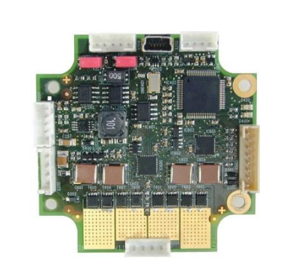
TMCM-1160
1-Axis Stepper
Controller / Driver
2.8 A / 48 V
USB, RS485, and CAN
Step/Dir Interface
sensOstep™ Encoder
+
UNIQUE FEATURES:
TRINAMIC Motion Control GmbH & Co. KG
Hamburg, Germany
www.trinamic.com
+
�TMCM-1160 TMCL Firmware V1.27 Manual (Rev. 1.04 / 2013-SEP-02)
Table of Contents
1
2
Features........................................................................................................................................................................... 4
Putting the Module into Operation ........................................................................................................................ 6
2.1
Basic Set-Up .......................................................................................................................................................... 6
2.1.1 Start the TMCL-IDE Software Development Environment ................................................................. 9
2.2
Using TMCL Direct Mode .................................................................................................................................. 10
2.2.1 Important Motor Settings ......................................................................................................................... 11
2.3
Testing with a Simple TMCL Program ......................................................................................................... 12
3
TMCL and the TMCL-IDE: Introduction ................................................................................................................. 13
3.1
Binary Command Format ................................................................................................................................ 13
3.1.1 Checksum Calculation ................................................................................................................................ 14
3.2
Reply Format ....................................................................................................................................................... 14
3.2.1 Status Codes ................................................................................................................................................. 15
3.3
Standalone Applications .................................................................................................................................. 15
3.4
TMCL Command Overview .............................................................................................................................. 16
3.4.1 TMCL Commands ......................................................................................................................................... 16
3.4.2 Commands Listed According to Subject Area .................................................................................... 17
3.5
The ASCII Interface ........................................................................................................................................... 21
3.5.1 Format of the Command Line ................................................................................................................. 21
3.5.2 Format of a Reply ....................................................................................................................................... 21
3.5.3 Configuring the ASCII Interface ............................................................................................................. 22
3.6
Commands ........................................................................................................................................................... 23
3.6.1 ROR (rotate right) ....................................................................................................................................... 23
3.6.2 ROL (rotate left) ........................................................................................................................................... 24
3.6.3 MST (motor stop)......................................................................................................................................... 25
3.6.4 MVP (move to position) ............................................................................................................................ 26
3.6.5 SAP (set axis parameter) ........................................................................................................................... 28
3.6.6 GAP (get axis parameter) .......................................................................................................................... 29
3.6.7 STAP (store axis parameter) ..................................................................................................................... 30
3.6.8 RSAP (restore axis parameter) ................................................................................................................. 31
3.6.9 SGP (set global parameter) ...................................................................................................................... 32
3.6.10 GGP (get global parameter)...................................................................................................................... 33
3.6.11 STGP (store global parameter) ................................................................................................................ 34
3.6.12 RSGP (restore global parameter) ............................................................................................................ 35
3.6.13 RFS (reference search) ................................................................................................................................ 36
3.6.14 SIO (set input / output) ............................................................................................................................. 37
3.6.15 GIO (get input /output) ............................................................................................................................. 39
3.6.16 CALC (calculate) ............................................................................................................................................ 42
3.6.17 COMP (compare)........................................................................................................................................... 43
3.6.18 JC (jump conditional) ................................................................................................................................. 44
3.6.19 JA (jump always) ......................................................................................................................................... 45
3.6.20 CSUB (call subroutine) ............................................................................................................................... 46
3.6.21 RSUB (return from subroutine) ................................................................................................................ 47
3.6.22 WAIT (wait for an event to occur) ......................................................................................................... 48
3.6.23 STOP (stop TMCL program execution) ................................................................................................... 49
3.6.24 SCO (set coordinate) ................................................................................................................................... 50
3.6.25 GCO (get coordinate) .................................................................................................................................. 51
3.6.26 CCO (capture coordinate) .......................................................................................................................... 52
3.6.27 ACO (accu to coordinate) .......................................................................................................................... 53
3.6.28 CALCX (calculate using the X register) .................................................................................................. 54
3.6.29 AAP (accumulator to axis parameter) .................................................................................................... 55
3.6.30 AGP (accumulator to global parameter) ............................................................................................... 56
3.6.31 CLE (clear error flags) ................................................................................................................................. 57
3.6.32 VECT (set interrupt vector) ........................................................................................................................ 58
3.6.33 EI (enable interrupt) ................................................................................................................................... 59
3.6.34 DI (disable interrupt) .................................................................................................................................. 60
3.6.35 RETI (return from interrupt) ..................................................................................................................... 61
www.trinamic.com
2
�TMCM-1160 TMCL Firmware V1.27 Manual (Rev. 1.04 / 2013-SEP-02)
3.6.36 Customer Specific TMCL Command Extension (UF0… UF7 / User Function) ............................... 62
3.6.37 Request Target Position Reached Event ............................................................................................... 62
3.6.38 TMCL Control Functions ............................................................................................................................. 63
4
Axis Parameters .......................................................................................................................................................... 65
4.1
stallGuard2 ........................................................................................................................................................... 72
4.2
coolStep Related Axis Parameters ................................................................................................................ 72
5
Global Parameters ...................................................................................................................................................... 74
5.1
Bank 0 ................................................................................................................................................................... 74
5.2
Bank 1 ................................................................................................................................................................... 76
5.3
Bank 2 ................................................................................................................................................................... 76
5.4
Bank 3 ................................................................................................................................................................... 77
6
Hints and Tips ............................................................................................................................................................. 78
6.1
Reference Search ............................................................................................................................................... 78
6.2
Changing the Prescaler Value of an Encoder ............................................................................................ 81
6.3
Using the RS485 Interface .............................................................................................................................. 82
7
TMCL Programming Techniques and Structure ................................................................................................. 83
7.1
Initialization ........................................................................................................................................................ 83
7.2
Main Loop ............................................................................................................................................................ 83
7.3
Using Symbolic Constants .............................................................................................................................. 83
7.4
Using Variables .................................................................................................................................................. 84
7.5
Using Subroutines ............................................................................................................................................. 84
7.6
Mixing Direct Mode and Standalone Mode ................................................................................................ 85
8
Life Support Policy ..................................................................................................................................................... 86
9
Revision History .......................................................................................................................................................... 87
9.1
Document Revision ........................................................................................................................................... 87
9.2
Firmware Revision ............................................................................................................................................ 87
10 References .................................................................................................................................................................... 88
www.trinamic.com
3
�TMCM-1160 TMCL Firmware V1.27 Manual (Rev. 1.04 / 2013-SEP-02)
4
1 Features
The TMCM-1160 is a single axis controller/driver module for 2-phase bipolar stepper motors with state of
the art feature set. It is highly integrated, offers a convenient handling and can be used in many
decentralized applications. The module can be mounted on the back of NEMA 23 (57mm flange size) or
NEMA 24 (60mm flange size) stepper motors and has been designed for coil currents up to 2.8 A RMS and
24 or 48 V DC supply voltage. With its high energy efficiency from TRINAMIC’s coolStep™ technology cost
for power consumption is kept down. The TMCL™ firmware allows for both, standalone operation and
direct mode.
MAIN CHARACTERISTICS
Motion controller
Motion profile calculation in real-time
On the fly alteration of motor parameters (e.g. position, velocity, acceleration)
High performance microcontroller for overall system control and serial communication protocol
handling
Bipolar stepper motor driver
Up to 256 microsteps per full step
High-efficient operation, low power dissipation
Dynamic current control
Integrated protection
stallGuard2 feature for stall detection
coolStep feature for reduced power consumption and heat dissipation
Encoder
sensOstep magnetic encoder (1024 increments per rotation) e.g. for step-loss detection under all
operating conditions and positioning supervision
Interface for connection of external incremental a/b/n encoder
Interfaces
- RS485 interface
- CAN (2.0B up to 1Mbit/s) interface
- USB full speed (12Mbit/s) interface
- Step/Direction interface (optically isolated)
- 3 inputs for stop switches and home switch (+24V compatible) with programmable pull-up
- 2 general purpose inputs (+24V compatible) and 2 general purpose outputs (open collector)
- Incremental a/b/n encoder interface (TTL and open-collector signals supported directly)
Safety features
- Shutdown input – driver will be disabled in hardware as long as this pin is left open or shorted to
ground
- Separate supply voltage inputs for driver and digital logic – driver supply voltage may be switched off
externally while supply for digital logic and therefore digital logic remains active
Software
TMCL:
standalone operation or remote controlled operation,
program memory (non volatile) for up to 2048 TMCL commands, and
PC-based application development software TMCL-IDE available for free.
Electrical and mechanical data
- Supply voltage: common supply voltages +12 V DC / +24 V DC / +48 V DC supported (+9 V… +51 V DC)
- Motor current: up to 2.8 A RMS (programmable)
Refer to separate Hardware Manual, too.
www.trinamic.com
�TMCM-1160 TMCL Firmware V1.27 Manual (Rev. 1.04 / 2013-SEP-02)
5
TRINAMICS UNIQUE FEATURES – EASY TO USE WITH TMCL
stallGuard2™
stallGuard2 is a high-precision sensorless load measurement using the back EMF on the
coils. It can be used for stall detection as well as other uses at loads below those which
stall the motor. The stallGuard2 measurement value changes linearly over a wide range of
load, velocity, and current settings. At maximum motor load, the value goes to zero or
near to zero. This is the most energy-efficient point of operation for the motor.
Load
[Nm]
stallGuard2
Initial stallGuard2
(SG) value: 100%
Max. load
stallGuard2 (SG) value: 0
Maximum load reached.
Motor close to stall.
Motor stalls
Figure 1.1 stallGuard2 load measurement SG as a function of load
coolStep™
coolStep is a load-adaptive automatic current scaling based on the load measurement via
stallGuard2 adapting the required current to the load. Energy consumption can be reduced
by as much as 75%. coolStep allows substantial energy savings, especially for motors
which see varying loads or operate at a high duty cycle. Because a stepper motor
application needs to work with a torque reserve of 30% to 50%, even a constant-load
application allows significant energy savings because coolStep automatically enables
torque reserve when required. Reducing power consumption keeps the system cooler,
increases motor life, and allows reducing cost.
0,9
Efficiency with coolStep
0,8
Efficiency with 50% torque reserve
0,7
0,6
0,5
Efficiency
0,4
0,3
0,2
0,1
0
0
50
100
150
200
250
300
350
Velocity [RPM]
Figure 1.2 Energy efficiency example with coolStep
www.trinamic.com
�TMCM-1160 TMCL Firmware V1.27 Manual (Rev. 1.04 / 2013-SEP-02)
6
2 Putting the Module into Operation
Here you can find basic information for putting your TMCM-1160 into operation. If you are already common
with TRINAMICs modules you may skip this chapter.
The things you need:
TMCM-1160
Interface (RS485/CAN/USB) suitable to your module with cables
Nominal supply voltage +24V DC (12 V DC / 48 V DC) for your module
TMCL-IDE program and PC
Stepper motor
PRECAUTIONS
Do not connect or disconnect the TMCM-1160 while powered!
Do not connect or disconnect the motor while powered!
Do not exceed the maximum power supply voltage of 51 V DC!
Note, that the module is not protected against reverse polarity!
START WITH POWER SUPPLY OFF!
2.1 Basic Set-Up
The following paragraph will guide you through the steps of connecting the unit and making first
movements with the motor.
CONNECTING THE MODULE
USB
Serial USB
interface
Converter
Converter
e.g. USB-2-485
CA
N
e.g. USB-2-X
CAN
Pin 2 CAN_L
Pin 1 CAN_H
Pin 3 GND
1
1
Motor
1
Motor
Figure 2.1: Starting up
www.trinamic.com
S/D
Encoder
1
USB
In/Out
POWER SUPPLY
Pin 1 VDriver
Pin 2 VLogic
Pin 3 Shutdown
Pin 4 GND
Interface
Power
RS485
Pin 5 RS485Pin 4 RS485+
Pin 3 GND
1
1
RS485
�TMCM-1160 TMCL Firmware V1.27 Manual (Rev. 1.04 / 2013-SEP-02)
1.
7
Connect power supply
Note:
- In order to enable motor driver stage connect /SHUTDOWN (pin 3) to power supply!
- In case separate power supplies for driver and logic are not used pin 2 (logic supply) and pin
3 (/SHUTDOWN input) of the power connector may be connected together in order to enable
driver stage.
Please refer to the TMCM-1160 Hardware Manual for further information about the power supply!
Pin
1
2
2.
Label
+VDriver
+VLogic
3
/SHUTDOWN
4
GND
Description
Module + driver stage power supply input
(Optional) separate digital logic power supply input
Shutdown input. Connect this input to +VDriver or +VLogic in order to activate
driver stage. Leaving this input open or connecting it to ground will disable
driver stage
Module ground (power supply and signal ground)
Choose your interface
a) Connect CAN or RS485
CAN interface will be de-activated in case USB is connected due to internal sharing of hardware
resources.
Pin
1
2
3
4
5
Label
CAN_H
CAN_L
GND
RS485+
RS485-
Description
CAN bus signal (dominant high)
CAN bus signal (dominant low)
Module ground (system and signal ground)
RS485 bus signal (non inverted)
RS485 bus signal (inverted)
b) Connect USB interface (as alternative to CAN and RS485; use a normal USB cable)
Download and install the file TMCM-1160.inf (www.trinamic.com).
Pin
1
2
3
4
5
Label
VBUS
DD+
ID
GND
www.trinamic.com
Description
+5V power
Data –
Data +
Not connected
Module ground
�TMCM-1160 TMCL Firmware V1.27 Manual (Rev. 1.04 / 2013-SEP-02)
3.
Connect In/Out connector (optional)
If you like to work with the GPIOs or switches, use the In/Out connector.
Label
Pin
4.
1
OUT_0
2
OUT_1
3
IN_0
4
IN_1
5
STOP_L
6
STOP_R
7
HOME
8
GND
Label
GND
+5V
ENC_A
ENC_B
ENC_N
Description
Module ground (system and signal ground)
+5V supply output for external encoder circuit (100 mA max.)
Encoder a channel input (internal pull-up)
Encoder b channel input (internal pull-up)
Optional encoder n / index channel input (internal pull-up)
Connect the motor
Pin
1
2
3
4
6.
Description
General purpose output, open drain (max. 1A)
Integrated freewheeling diode connected to +VLogic
General purpose output, open drain (max. 1A)
Integrated freewheeling diode connected to +VLogic
General purpose input (analog and digital), +24V compatible
Resolution when used as analog input: 12bit (0..4095)
General purpose input (analog and digital), +24V compatible
Resolution when used as analog input: 12bit (0..4095)
Left stop switch input (digital input), +24V compatible, programmable internal
pull-up to +5V
Right stop switch input (digital input), +24V compatible, programmable
internal pull-up to +5V
Home switch input (digital input), +24V compatible, programmable internal
pull-up to +5V
Module ground (system and signal ground)
Connect the encoder (optional)
If you like to work with encoder, use the encoder connector.
Pin
1
2
3
4
5
5.
8
Label
OA1
OA2
OB1
OB2
Description
Motor coil A
Motor coil A
Motor coil B
Motor coil B
Switch ON the power supply
Turn power ON. The green LED for power lights up and the motor is powered but in standstill
now.
If this does not occur, switch power OFF and check your connections as well as the power
supply!
www.trinamic.com
�TMCM-1160 TMCL Firmware V1.27 Manual (Rev. 1.04 / 2013-SEP-02)
2.1.1
Start the TMCL-IDE Software Development Environment
The TMCL-IDE is available on www.trinamic.com.
Installing the TMCL-IDE:
Make sure the COM port you intend to use is not blocked by another program.
Open TMCL-IDE by clicking TMCL.exe.
Choose Setup and Options and thereafter the Connection tab.
Choose COM port and type with the parameters shown in
Figure 2.2 (baud rate 9600). Click OK.
USB interface
If the file TMCM-1160.inf is installed correctly, the module will be identified automatically.
Figure 2.2 Setup dialogue and connection tab of the TMCL-IDE.
Please refer to the TMCL-IDE User Manual for more information (see www.TRINAMIC.com).
www.trinamic.com
9
�TMCM-1160 TMCL Firmware V1.27 Manual (Rev. 1.04 / 2013-SEP-02)
10
2.2 Using TMCL Direct Mode
1.
Start TMCL Direct Mode.
Direct Mode
2.
If the communication is established the TMCM-1160 is automatically detected.
If the module is not detected, please check all points above (cables, interface, power supply,
COM port, baud rate).
3.
Issue a command by choosing Instruction, Type (if necessary), Motor, and Value and click
Execute to send it to the module.
Examples:
- ROR rotate right, motor 0, value 500
- MST motor stop, motor 0
-> Click Execute. The motor is rotating now.
-> Click Execute. The motor stops now.
Top right of the TMCL Direct Mode window is the button Copy to editor. Click here to copy the chosen
command and create your own TMCL program. The command will be shown immediately on the editor.
Note:
Chapter 4 of this manual (axis parameters) includes a diagram which points out the coolStep related axis
parameters and their functions.
www.trinamic.com
�TMCM-1160 TMCL Firmware V1.27 Manual (Rev. 1.04 / 2013-SEP-02)
2.2.1
11
Important Motor Settings
There are some axis parameters which have to be adjusted right in the beginning after installing your
module. Please set the upper limiting values for the speed (axis parameter 4), the acceleration (axis
parameter 5), and the current (axis parameter 6). Further set the standby current (axis parameter 7) and
choose your microstep resolution with axis parameter 140. Please use the SAP (Set Axis Parameter)
command for adjusting these values. The SAP command is described in paragraph 3.6.5. You can use the
TMCL-IDE direct mode for easily configuring your module.
Attention:
The most important motor setting is the absolute maximum motor current setting, since too high values
might cause motor damage!
IMPORTANT AXIS PARAMETERS FOR MOTOR SETTING
Number
4
Axis Parameter
Maximum
positioning
speed
5
Maximum
acceleration
6
Absolute max.
current
(CS / Current
Scale)
Description
Should not exceed the physically highest possible
value. Adjust the pulse divisor (axis parameter 154), if
the speed value is very low (