0
登录后你可以
  • 下载海量资料
  • 学习在线课程
  • 观看技术视频
  • 写文章/发帖/加入社区
会员中心
创作中心
发布
  • 发文章

  • 发资料

  • 发帖

  • 提问

  • 发视频

创作活动
TMCM-1640-CABLE

TMCM-1640-CABLE

  • 厂商:

    TRINAMIC

  • 封装:

  • 描述:

    CABLE LOOM FOR TMCM-1640

  • 详情介绍
  • 数据手册
  • 价格&库存
TMCM-1640-CABLE 数据手册
MODULES FOR BLDC MOTORS MODULES Hardware Version 1.0 HARDWARE MANUAL + + TMCM-1640 1-axis BLDC controller / driver 5A / 24V DC RS485 + USB interface hall sensor interface encoder interface + TRINAMIC Motion Control GmbH & Co. KG Hamburg, Germany www.trinamic.com + TMCM-1640 Hardware Manual (V1.05 / 2017-MAR-12) Table of Contents 1 2 3 4 5 6 7 8 Life support policy ....................................................................................................................................................... 3 Features ........................................................................................................................................................................... 4 Order codes .................................................................................................................................................................... 5 Mechanical and electrical interfacing ..................................................................................................................... 6 4.1 Controller/driver board size and mounting holes ..................................................................................... 6 4.2 Connectors ............................................................................................................................................................. 7 4.2.1 Power connector............................................................................................................................................ 8 4.2.2 Motor connector............................................................................................................................................. 8 4.2.3 Hall sensor connector .................................................................................................................................. 9 4.2.4 Encoder connector......................................................................................................................................... 9 4.2.5 USB connector ................................................................................................................................................ 9 4.2.6 GPIOs and RS485 connector ..................................................................................................................... 10 4.3 Input/output circuits ......................................................................................................................................... 11 4.3.1 Hall sensor input ......................................................................................................................................... 11 4.3.2 Encoder input ............................................................................................................................................... 11 4.3.3 General purpose inputs/outputs ............................................................................................................. 12 Operational ratings .................................................................................................................................................... 13 Functional description .............................................................................................................................................. 14 6.1 System architecture ........................................................................................................................................... 14 6.2 Microcontroller .................................................................................................................................................... 14 6.2.1 TMC603 3-phase pre-driver ........................................................................................................................ 14 Revision history .......................................................................................................................................................... 15 7.1 Document revision ............................................................................................................................................ 15 7.2 Hardware revision ............................................................................................................................................. 15 References..................................................................................................................................................................... 15 Copyright © 2011-2017, TRINAMIC Motion Control GmbH & Co. KG 2 TMCM-1640 Hardware Manual (V1.05 / 2017-MAR-12) 1 Life support policy TRINAMIC Motion Control GmbH & Co. KG does not authorize or warrant any of its products for use in life support systems, without the specific written consent of TRINAMIC Motion Control GmbH & Co. KG. Life support systems are equipment intended to support or sustain life, and whose failure to perform, when properly used in accordance with instructions provided, can be reasonably expected to result in personal injury or death. © TRINAMIC Motion Control GmbH & Co. KG 2011-2017 Information given in this data sheet is believed to be accurate and reliable. However neither responsibility is assumed for the consequences of its use nor for any infringement of patents or other rights of third parties, which may result from its use. Specifications are subject to change without notice. Copyright © 2011-2017, TRINAMIC Motion Control GmbH & Co. KG 3 TMCM-1640 Hardware Manual (V1.05 / 2017-MAR-12) 4 2 Features The TMCM-1640 is a highly compact controller/driver module for brushless DC (BLDC) motors with up to 5A coil current, optional encoder and/or hall sensor feedback. For communication the module offers RS485 and (mini-)USB interfaces. Applications  Compact single-axis brushless DC motor solutions Electrical data  Supply voltage: +24VDC nom. (+12V… +28.5V DC)  Motor current: up to 5A RMS (programmable) Integrated motion controller  High performance ARM Cortex™-M3 microcontroller for system control and communication protocol handling Integrated driver  High performance integrated pre-driver (TMC603)  High-efficient operation, low power dissipation (MOSFETs with low RDS(ON))  Dynamic current control  Integrated protection Interfaces  USB: mini-USB connector, full speed (12Mbit/s) serial communication interface  RS485 serial communication interface  Hall sensor interface (+5V TTL or open-collector signals)  Encoder interface (+5V TTL or open-collector signals)  3 general purpose inputs: 2x digital (+5V / +24V compatible), 1x analogue (0… 10V)  1 general purpose output (open-drain) Software  Available with TMCL™  stand-alone operation or remote controlled operation  program memory (non volatile) for up to 2048 TMCL™ commands  PC-based application development software TMCL-IDE  PC-based application development software TMCL-BLDC for initial settings Please refer to separate TMCM-1640 TMCL™ Firmware Manual for further information Copyright © 2011-2017, TRINAMIC Motion Control GmbH & Co. KG TMCM-1640 Hardware Manual (V1.05 / 2017-MAR-12) 5 3 Order codes Cables are not included. Add the TMCM-1640-CABLE to your order if required. Order code TMCM-1640 Component parts TMCM-1640-CABLE Related motors QBL4208-41-04-006 QBL4208-61-04-013 Dimensions [mm] Description 1-axis BLDC controller/driver module with up to 5A / 42 x 42 x 15 28.5V. RS485 and USB 2.0 interface Cable-loom for TMCM-1640 QMot BLDC motor 42 mm, 4000RPM, 0.06Nm QMot BLDC motor 42 mm, 4000RPM, 0.13Nm Table 3.1: Order codes Copyright © 2011-2017, TRINAMIC Motion Control GmbH & Co. KG 42 x 42 x 41 42 x 42 x 61 TMCM-1640 Hardware Manual (V1.05 / 2017-MAR-12) 6 4 Mechanical and electrical interfacing 4.1 Controller/driver board size and mounting holes The dimensions of the controller/driver board (TMCM-164) are approx. 42mm x 42mm in order to fit on the back side of a 42mm NEMA 17 brushless DC motor. Maximum component height (height above PCB level) without mating connectors is around 10mm and about 3mm below PCB level. There are two mounting holes for M3 screws for mounting the board directly to a NEMA 17/42mm flange size brushless DC motor. 39.0 36.5 3 M3 36.5 42.0 39.0 5.5 5.5 3 42.0 Figure 4.1: Module dimension and position of mounting holes Copyright © 2011-2017, TRINAMIC Motion Control GmbH & Co. KG TMCM-1640 Hardware Manual (V1.05 / 2017-MAR-12) 7 4.2 Connectors The controller/driver board offers 6 connectors including the motor connector which is used for attaching the motor coils to the electronics. In addition to the power connector there is one connector for (optional) motor hall sensor signals and one connector for (optional) incremental encoder signals. For serial communication a mini-USB connector has been integrated on-board. There is an additional connector for RS485 serial communication, 3 general purpose inputs and one output. General purpose inputs and output may have dedicated functionality depending on firmware. 1 GPIO RS485 USB 1 Hall Power 1 1 Encoder 1 Motor Figure 4.2: Overview connectors Domain USB Hall Connector type Tyco electronics (formerly AMP) MTA-100 series (3-640456-2), 2 pol., male Tyco electronics (formerly AMP) MTA-100 series (3-640456-3), 3 pol., male 5-pin standard mini-USB connector, female 2mm pitch 5 pin JST B5B-PH-K connector Encoder 2mm pitch 5 pin JST B5B-PH-K connector I/O, RS485 2mm pitch 8 pin JST B8B-PH-K connector Power Motor Mating connector type MTA 100 series (3-640440-2), 2 pol., female MTA 100 series (3-640440-3), 3 pol., female 5-pin standard mini-USB connector, male Housing: JST PHR-5 Crimp contacts: BPH-002T-P0.5S (0.5-0.22mm) Housing: JST PHR-5 Crimp contacts: BPH-002T-P0.5S (0.5-0.22mm) Housing: JST PHR-8 Crimp contacts: BPH-002T-P0.5S (0.5-0.22mm) Copyright © 2011-2017, TRINAMIC Motion Control GmbH & Co. KG TMCM-1640 Hardware Manual (V1.05 / 2017-MAR-12) 8 4.2.1 Power connector A 2-pin Tyco electronics (formerly AMP) MTA-100 series connector (3-640456-2) is used as power connector on-board. Mating connector: Tyco electronics (formerly AMP) MTA-100 series (3-640440-2) 2 1 Pin Label 1 +U 2 GND Description Module + driver stage power supply input Module ground (power supply and signal ground) Table 4.1: Connector for power supply Please note, that there is no protection against reverse polarity and only limited protection against voltages above the upper maximum limit. The power supply typically should be within a range of +9 to +28.5V. When using supply voltages near the upper limit, a regulated power supply is mandatory. Please ensure that enough power filtering capacitors are available in the system (2200µF or more recommended) in order to absorb mechanical energy fed back by the motor in stalling conditions and in order to prevent any voltage surge e.g. during power-on (especially with longer power supply cables as there are only ceramic filter capacitors on-board). In larger systems a zener diode circuitry might be required in order to limit the maximum voltage when the motor is operated at high velocities. The power supply should be designed in a way that it supplies the nominal motor voltage at the desired maximum motor power. In no case shall the supply value exceed the upper voltage limit. To ensure reliable operation of the unit, the power supply has to have a sufficient output capacitor and the supply cables should have a low resistance, so that the chopper operation does not lead to an increased power supply ripple directly at the unit. Power supply ripple due to the chopper operation should be kept at a maximum of a few 100mV. Guidelines for power supply: a) keep power supply cables as short as possible b) use large diameters for power supply cables c) add 2200µF or larger filter capacitors near the motor driver unit especially if the distance to the power supply is large (i.e. more than 2-3m) 4.2.2 Motor connector A 3-pin Tyco electronics (formerly AMP) MTA-100 series connector (3-640456-3) is used as motor connector on-board. Mating connector: Tycos electronics (formerly AMP) MTA-100 series (3-640440-3) 3 1 Pin 1 2 3 Label BM1 BM2 BM3 Description Motor coil phase 1 / U Motor coil phase 2 / V Motor coil phase 3 / W Table 4.2: Connector for brushless DC motor Copyright © 2011-2017, TRINAMIC Motion Control GmbH & Co. KG TMCM-1640 Hardware Manual (V1.05 / 2017-MAR-12) 9 4.2.3 Hall sensor connector A 2mm pitch 5 pin JST B5B-PH-K connector is used for hall sensor signals. Mating connector housing: PHR-5 Mating connector contacts: SPH-002T-P0.5S. 5 1 Pin 1 2 3 4 5 Label GND +5V HALL_1 HALL_2 HALL_3 Description Hall sensor supply and signal ground +5V output for hall sensor supply Hall sensor signal 1 Hall sensor signal 2 Hall sensor signal 3 Table 4.3: Connector for hall sensor signals 4.2.4 Encoder connector A 2mm pitch 5 pin JST B5B-PH-K connector is used for encoder signals. Mating connector housing: PHR-5 Mating connector contacts: SPH-002T-P0.5S. 5 1 Pin 1 2 3 4 5 Label GND +5V A B N Description Hall sensor supply and signal ground +5V output for encoder supply (max. 100mA) Encoder channel a Encoder channel b Encoder index / null channel Table 4.4: Connector for encoder signals 4.2.5 USB connector A 5-pin standard mini-USB connector is available on board for serial communication. 5 1 Pin 1 2 3 4 5 Label VBUS DD+ ID GND Description +5V power Data – Data + Not connected ground Table 4.5: Mini USB connector Copyright © 2011-2017, TRINAMIC Motion Control GmbH & Co. KG TMCM-1640 Hardware Manual (V1.05 / 2017-MAR-12) 10 4.2.6 GPIOs and RS485 connector A 2mm pitch 8 pin JST B8B-PH-K connector is used for connecting general purpose inputs and outputs. Mating connector housing: PHR-8 Mating connector contacts: SPH-002T-P0.5S 1 8 Pin 1 2 Label GND +5V 3 AIN 4 IN_0 5 IN_1 6 7 OUT RS485+ Description Signal and system ground +5V output for supply of external circuit (max. 100mA) Analog input (0… 10V), may be used as velocity control input in standalone mode (depending on firmware) Digital input, may be used as stop (STOP_R) / limit switch input (depending on firmware) Digital input, may be used as stop (STOP_L) / limit switch input (depending on firmware) Digital output (open-drain, max. 100mA) RS485 2-wire serial interface (non-inverted signal) 8 RS485- RS485 2-wire serial interface (inverted signal) Table 4.6: General purpose input/output connector Copyright © 2011-2017, TRINAMIC Motion Control GmbH & Co. KG TMCM-1640 Hardware Manual (V1.05 / 2017-MAR-12) 11 4.3 Input/output circuits 4.3.1 Hall sensor input The hall sensor input circuit supports +5V push-pull (TTL) and open-collector hall sensor signals. In order to support open-collector signals the input circuit offers 2k7 pull-up resistors to +5V (generated on-board from power supply voltage). Figure 4.3: Hall sensor input circuit 4.3.2 Encoder input The encoder input circuit supports +5V push-pull (TTL) and open-collector hall sensor signals. In order to support open-collector signals the input circuit offers 2k7 pull-up resistors to +5V (+5V generated on-board from power supply voltage). Figure 4.4: Encoder input circuit Copyright © 2011-2017, TRINAMIC Motion Control GmbH & Co. KG TMCM-1640 Hardware Manual (V1.05 / 2017-MAR-12) 4.3.3 General purpose inputs/outputs Figure 4.5: General purpose input/output circuit Copyright © 2011-2017, TRINAMIC Motion Control GmbH & Co. KG 12 TMCM-1640 Hardware Manual (V1.05 / 2017-MAR-12) 13 5 Operational ratings The operational ratings shown below should be used as design values. In no case should the maximum values been exceeded during operation. Symbol Parameter Min Typ Max Unit +U Power supply voltage for operation 9 24 28.5 V DC ICOIL Continuous motor current (RMS) 0 3 5 A ISUPPLY Power supply current
TMCM-1640-CABLE
物料型号:TMCM-1640 器件简介:TMCM-1640 是一款用于无刷直流(BLDC)电机的紧凑型控制器/驱动模块,支持高达 5A 的线圈电流,可选编码器和/或霍尔传感器反馈。

模块提供 RS485 和 (mini-)USB 接口进行通信。

引脚分配: - 电源连接器:+U(1号引脚,模块+驱动级电源输入),GND(2号引脚,模块地(电源和信号地)) - 电机连接器:BM1(1号引脚,电机线圈相位1/U),BM2(2号引脚,电机线圈相位2/V),BM3(3号引脚,电机线圈相位3/W) - 霍尔传感器连接器:GND(1号引脚,霍尔传感器供电和信号地),+5V(2号引脚,+5V 输出用于霍尔传感器供电),HALL1(3号引脚,霍尔传感器信号1),HALL2(4号引脚,霍尔传感器信号2),HALL3(5号引脚,霍尔传感器信号3) - 编码器连接器:GND(1号引脚,霍尔传感器供电和信号地),+5V(2号引脚,+5V 输出用于编码器供电(最大 100mA)),A(3号引脚,编码器通道 a),B(4号引脚,编码器通道 b),N(5号引脚,编码器索引/零通道) 参数特性: - 供电电压:+24VDC 标称值(+12V… +28.5V DC) - 电机电流:高达 5A RMS(可编程) - 集成运动控制器:高性能 ARM Cortex™-M3 微控制器,用于系统控制和通信协议处理 - 集成驱动器:高性能集成预驱动器(TMC603),高效操作,低功耗(具有低 RDS(ON) 的 MOSFET),动态电流控制,集成保护 功能详解:TMCM-1640 集成了微控制器和 TMCL™(Trinamic 运动控制语言)操作系统。

运动控制实时任务由 TMC603A 实现。

ARM Cortex™-M3 CPU 32位处理器用于运行 TMCL™ 操作系统并控制 TMC603A。

微控制器的闪存 ROM 存储 TMCL™ 操作系统。

EEPROM 存储器用于永久存储配置数据。

微控制器运行 TMCL™ 操作系统,使其能够执行从主机通过接口发送到模块的 TMCL™ 命令。

微控制器解释 TMCL™ 命令并控制 TMC603A,后者执行运动命令。

应用信息:适用于紧凑型单轴无刷直流电机解决方案。

封装信息:控制器/驱动板尺寸约为 42mm x 42mm,以便安装在 42mm NEMA 17 无刷直流电机的背面。

最大元件高度(高于 PCB 级别)约为 10mm,PCB 级别下方约 3mm。

有两个 M3 螺钉安装孔,用于将板直接安装到 NEMA 17/42mm 法兰尺寸无刷直流电机。
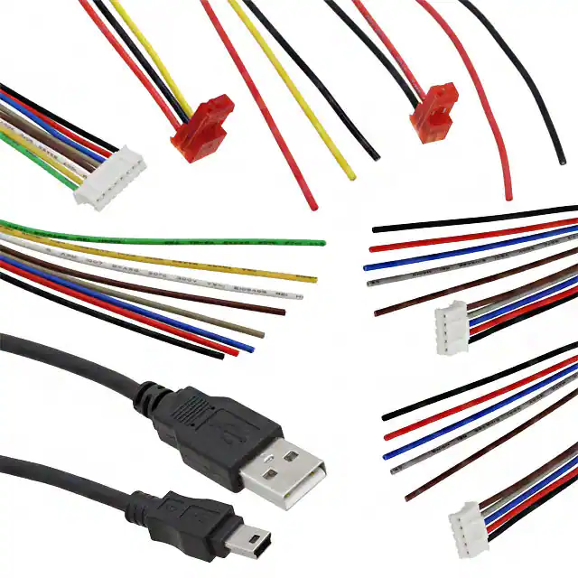
TMCM-1640-CABLE 价格&库存

很抱歉,暂时无法提供与“TMCM-1640-CABLE”相匹配的价格&库存,您可以联系我们找货

免费人工找货
TMCM-1640-CABLE

    库存:0