1.5SMC75A

1.5SMC75A

  • 厂商:

    TSC

  • 封装:

  • 描述:

    1.5SMC75A - 1500 Watts Surface Mount Transient Voltage Suppressor - Taiwan Semiconductor Company, Lt...

  • 详情介绍
  • 数据手册
  • 价格&库存
1.5SMC75A 数据手册
1.5SMC SERIES 1500 Watts Surface Mount Transient Voltage Suppressor SMC/DO-214AB .124(3.15) .112(2.85) .245(6.22) .220(5.59) Features For surface mounted application in order to optimize board space Low profile package Built-in strain relief Glass passivated junction Excellent clamping capability Fast response time: Typically less than 1.0ps from 0 volt to BV min. Typical IR less than 1μA above 10V High temperature soldering guaranteed: 260oC / 10 seconds at terminals Plastic material used carries Underwriters Laboratory Flammability Classification 94V-0 1500 watts peak pulse power capability with a 10 x 1000 us waveform by 0.01% duty cycle .280(7.11) .260(6.60) .012(.31) .006(.15) .103(2.62) .079(2.00) .008(.20) .071(1.8) .039(1.0) .320(8.13) .305(7.75) .004(.10) Dimensions in inches and (millimeters) Mechanical Data Case: Molded plastic Terminals: Solder plated Polarity: Indicated by cathode band Standard packaging: 16mm tape (EIA STD RS-481) Weight: 0.21gram Maximum Ratings and Electrical Characteristics Rating at 25 oC ambient temperature unless otherwise specified. Type Number o Peak Power Dissipation at TA=25 C, Tp=1ms (Note 1) Power Dissipation on Intinite Heatsink, TA=50oC Peak Forward Surge Current, 8.3 ms Single Half Sine-wave Superimposed on Rated Load (JEDEC method) (Note 2, 3) - Unidirectional Only Thermal Resistance Junction to Ambient Air (Note 4) Thermal Resistance Junction to Leads Operating and Storage Temperature Range Notes: Symbol PPK PM(AV) IFSM RθJA RθJL Value Minimum 1500 6.5 200 50 15 -55 to + 150 Units Watts W Amps o o C/W C/W o C Devices for Bipolar Applications 1. Non-repetitive Current Pulse Per Fig. 3 and Derated above TA=25oC Per Fig. 2. 2. Mounted on 8.0mm2 (.013mm Thick) Copper Pads to Each Terminal. 3. 8.3ms Single Half Sine-wave or Equivalent Square Wave, Duty Cycle=4 Pulses Per Minute Maximum. 4. Mounted on 5.0mm2(.013mm thick) land areas. 1. For Bidrectional Use C or CA Suffix for Types 1.5SMC6.8 through Types 1.5SMC200A. 2. Electrical Characteristics Apply in Both Directions. TJ, TSTG - 546 - Version: A06 RATINGS AND CHARACTERISTIC CURVES (1.5SMC SERIES) FIG.1- PEAK PULSE POWER RATING CURVE 100 200 FIG.2- PULSE DERATING CURVE PPPM, PEAK PULSE POWER, KW 10 1 DERATING IN PERCENTAGE. % NON-REPETITIVE PULSE WAVEFORM SHOWN in FIG.3 O TA = 25 C PEAK PULSE POWER (PPP) or CURRENT (IPPM) 150 100 50 0.1 0.1 s 1s 10 s 100 s 1.0ms 10ms 0 0 25 50 75 100 125 O 150 175 200 tp, PULSE WIDTH, sec. TA, AMBIENT TEMPERATURE. ( C) FIG.3- CLAMPING POWER PULSE WAVEFORM 150 FIG.4- MAXIMUM NON-REPETITIVE FORWARD SURGE CURRENT UNIDIRECTIONAL ONLY 200 tr = 10 sec PEAK PULSE CURRENT - % IFSM, PEAK FORWARD SURGE CURRENT, AMPERES 100 Peak Value IPPM PULSE WIDTH (td) is DEFINED as the POINT WHERE the PEAK CURRENT DECAYS to 50% of IPPM 100 8.3ms Single Half Sine Wave JEDEC Method Tj=Tj max. 50 Half Value - IPPM 2 10/1000 sec. WAVEFORM as DEFINED by R.E.A. 0 0 td 1.0 2.0 3.0 4.0 10 1 10 100 t, TIME, ms NUMBER OF CYCLES AT 60Hz FIG.5- TYPICAL JUNCTION CAPACITANCE UNIDIRECTIONAL 10000 UNIDIRECTIONAL BIDIRECTIONA CJ, JUNCTION CAPACITANCE. (pF) VR=0 1000 100 Tj = 25 C f=1.0MHz Vsig=50mVp-p VR-RATED STAND-OFF VOLTAGE O 10 1 10 100 200 V(BR), BREAKDOWN VOLTAGE. VOLTS - 547 - Version: A06 ELECTRICAL CHARACTERISTICS (TA=25OC unless otherwise noted) GENERAL Device PART Marking NUMBER Code 1.5SMC6.8 1.5SMC6.8A 1.5SMC7.5 1.5SMC7.5A 1.5SMC8.2 1.5SMC8.2A 1.5SMC9.1 1.5SMC9.1A 1.5SMC10 1.5SMC10A 1.5SMC11 1.5SMC11A 1.5SMC12 1.5SMC12A 1.5SMC13 1.5SMC13A 1.5SMC15 1.5SMC15A 1.5SMC16 1.5SMC16A 1.5SMC18 1.5SMC18A 1.5SMC20 1.5SMC20A 1.5SMC22 1.5SMC22A 1.5SMC24 1.5SMC24A 1.5SMC27 1.5SMC27A 1.5SMC30 1.5SMC30A 1.5SMC33 1.5SMC33A 1.5SMC36 1.5SMC36A 1.5SMC39 1.5SMC39A 1.5SMC43 1.5SMC43A 1.5SMC47 1.5SMC47A 1.5SMC51 1.5SMC51A 1.5SMC56 1.5SMC56A 1.5SMC62 1.5SMC62A 1.5SMC68 1.5SMC68A 1.5SMC75 1.5SMC75A 1.5SMC82 1.5SMC82A 1.5SMC91 1.5SMC91A DDJ DEJ DFJ DGJ DHJ DKJ DLJ DMJ DNJ DPJ DQJ DRJ DSJ DTJ DUJ DVJ DWJ DXJ DYJ DZJ EDJ EEJ EFJ EGJ EHJ EKJ ELJ EMJ ENJ EPJ EQJ ERJ ESJ ETJ EUJ EVJ EWJ EXJ EYJ EZJ FDJ FEJ FFJ FGJ FHJ FKJ FLJ FMJ FNJ FPJ FQJ FRJ FSJ FTJ FUJ FVJ Maximum Maximum Maximum Maximum Breakdown Voltage Test Stand-Off Current Voltage Reverse Leakage Peak Surge Clamping Temperature VBR @ IT VWM at Vwm Current IPPM Voltage at IPPM Coefficient (Volts) (Note 1) O Min Max (mA) (Volts) ID (uA) (Note 2)(Amps) VC(Volts) of VBR(% / C) 6.12 6.45 6.75 7.13 7.38 7.79 8.19 8.65 9.00 9.50 9.90 10.5 10.8 11.4 11.7 12.4 13.5 14.3 14.4 15.2 16.2 17.1 18.0 19.0 19.8 20.9 21.6 22.8 24.3 25.7 27.0 28.5 29.7 31.4 32.4 34.2 35.1 37.1 38.7 40.9 42.3 44.7 45.9 48.5 50.4 53.2 55.8 58.9 61.2 64.6 67.5 71.3 73.8 77.9 81.9 86.5 7.48 7.14 8.25 7.88 9.02 8.61 10.0 9.55 11.0 10.5 12.1 11.6 13.2 12.6 14.3 13.7 16.5 15.8 17.6 16.8 19.8 18.9 22.0 21.0 24.2 23.1 26.4 25.2 29.7 28.4 33.0 31.5 36.3 34.7 39.6 37.8 42.9 41.0 47.3 45.2 51.7 49.4 56.1 53.6 61.8 58.8 68.2 65.1 74.8 71.4 82.5 78.8 90.2 86.1 100.0 95.50 10 10 10 10 10 10 1.0 1.0 1.0 1.0 1.0 1.0 1.0 1.0 1.0 1.0 1.0 1.0 1.0 1.0 1.0 1.0 1.0 1.0 1.0 1.0 1.0 1.0 1.0 1.0 1.0 1.0 1.0 1.0 1.0 1.0 1.0 1.0 1.0 1.0 1.0 1.0 1.0 1.0 1.0 1.0 1.0 1.0 1.0 1.0 1.0 1.0 1.0 1.0 1.0 1.0 5.50 5.80 6.05 6.40 6.63 7.02 7.37 7.78 8.10 8.55 8.92 9.40 9.72 10.2 10.5 11.1 12.1 12.8 12.9 13.6 14.5 15.3 16.2 17.1 17.8 18.8 19.4 20.5 21.8 23.1 24.3 25.6 26.8 28.2 29.1 30.8 31.6 33.3 34.8 36.8 38.1 40.2 41.3 43.6 45.4 47.8 50.2 53.0 55.1 58.1 60.7 64.1 66.4 70.1 73.7 77.8 1000 1000 500 500 200 200 50 50 10 10 5.0 5.0 5.0 5.0 5.0 5.0 5.0 5.0 5.0 5.0 5.0 5.0 5.0 5.0 5.0 5.0 5.0 5.0 5.0 5.0 5.0 5.0 5.0 5.0 5.0 5.0 5.0 5.0 5.0 5.0 5.0 5.0 5.0 5.0 5.0 5.0 5.0 5.0 5.0 5.0 5.0 5.0 5.0 5.0 5.0 5.0 145 150 134 139 126 130 114 117 105 108 97 100 91 94 82 86 71 74 67 70 59 60 54 56 10.8 10.5 11.7 11.3 12.5 12.1 13.8 13.4 15.0 14.5 16.2 15.6 17.3 16.7 19.0 18.2 22.0 21.2 23.5 22.5 26.5 25.2 29.1 27.7 0.057 0.057 0.061 0.061 0.065 0.065 0.068 0.068 0.073 0.073 0.075 0.075 0.078 0.078 0.081 0.081 0.084 0.084 0.086 0.086 0.088 0.088 0.090 0.090 Dimensions in inches and (millimeters) 49 51 45 47 40 42 36 38 33 34 30 31 27 29 25 26 23 24 21 22 19 20 17 18 16 17 14 15 13 13.9 12 12.6 31.9 30.6 34.7 33.2 39.1 37.5 43.5 41.4 47.7 45.7 52.0 49.9 56.4 53.9 61.9 59.3 67.8 64.8 73.5 70.1 80.5 77.0 89.0 85.0 98.0 92.0 108.0 103.0 118.0 113.0 131.0 125.0 0.092 0.092 0.094 0.094 0.096 0.096 0.097 0.097 0.098 0.098 0.099 0.099 0.100 0.100 0.101 0.101 0.101 0.101 0.102 0.102 0.103 0.103 0.104 0.104 0.104 0.104 0.105 0.105 0.105 0.105 0.106 0.106 - 548 - ELECTRICAL CHARACTERISTICS (TA=25OC unless otherwise noted) Breakdown Voltage Stand-Off Maximum Maximum Maximum Maximum VBR GENERAL Device Test Current Voltage Reverse Leakage Peak Surge Clamping Temperature (Volts) (Note 1) @IT(mA) PART Marking VWM at Vwm Current IPPM Voltage at IPPM Coefficient O NUMBER Code Min Max (Volts) ID (uA) (Note 2)(Amps) VC(Volts) of VBR(% / C) 1.5SMC100 FWJ 90.0 110.0 1.0 81.0 5.0 10.9 144.0 0.106 1.5SMC100A FXJ 95.0 105.0 1.0 85.5 5.0 11.4 137.0 0.106 1.5SMC110 FYJ 99.0 121.0 1.0 89.2 5.0 9.9 158.0 0.107 1.5SMC110A FZJ 105.0 116.0 1.0 94.0 5.0 10.3 152.0 0.107 1.5SMC120 GDJ 108.0 132.0 1.0 97.2 5.0 9.1 173.0 0.107 1.5SMC120A GEJ 114.0 126.0 1.0 102.0 5.0 9.5 165.0 0.107 1.5SMC130 GFJ 117.0 143.0 1.0 106.0 5.0 8.4 187.0 0.107 1.5SMC130A GGJ 124.0 137.0 1.0 111.0 5.0 8.7 179.0 0.107 1.5SMC150 GHJ 135.0 165.0 1.0 121.0 5.0 7.3 215.0 0.108 1.5SMC150A GKJ 143.0 158.0 1.0 128.0 5.0 7.6 207.0 0.108 1.5SMC160 GLJ 144.0 176.0 1.0 130.0 5.0 6.8 230.0 0.108 1.5SMC160A GMJ 152.0 168.0 1.0 136.0 5.0 7.1 219.0 0.108 1.5SMC170 GNJ 153.0 187.0 1.0 138.0 5.0 6.4 244.0 0.108 1.5SMC170A GPJ 162.0 179.0 1.0 145.0 5.0 6.7 234.0 0.108 1.5SMC180 GQJ 162.0 198.0 1.0 146.0 5.0 6.1 258.0 0.108 1.5SMC180A GRJ 171.0 189.0 1.0 154.0 5.0 6.4 246.0 0.108 1.5SMC200 GSJ 180.0 220.0 1.0 162.0 5.0 5.4 287.0 0.108 1.5SMC200A GTJ 190.0 210.0 1.0 171.0 5.0 5.7 274.0 0.108 Notes: 1. VBR measured after IT applied for 300us, IT =square wave pulse or equivalent. 2. Surge current waveform per Figure 3 and derate per Figure 2. 3. For bipolar types having VWM of 10 volts and under, the ID limit is doubled. 4. For bidirectional use C or CA suffix for types 1.5SMC 6.8 through 1.5SMC200A. 5. All terms and symbols are consistent with ANSI/IEEE C62.35. - 549 -
1.5SMC75A
物料型号: - 型号为1.5SMC系列,具体型号包括1.5SMC6.8、1.5SMC7.5等,直至1.5SMC200A。
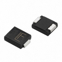
器件简介: - 1.5SMC系列为表面贴装型瞬态电压抑制器,采用SMC/DO-214AB封装,适用于优化板空间的表面贴装应用,具有低轮廓和内置的应力缓解功能。

引脚分配: - 极性通过阴极带表示。

参数特性: - 峰值脉冲功率:在25°C环境温度下,1ms脉冲时间,最小1500瓦特。 - 功率耗散:在无限大散热器上,环境温度为50°C时,平均功率耗散为6.5瓦特。 - 峰值正向浪涌电流:按照JEDEC方法,8.3ms单半正弦波叠加在额定负载上,单向使用时为200安培。 - 热阻:结到环境空气的热阻为50°C/W,结到引线的热阻为15°C/W。 - 工作和储存温度范围:-55到+150°C。

功能详解: - 器件具有优异的钳位能力,快速响应时间(从0伏到BV最小值的典型时间小于1.0ps)。 - 典型IR在10V以上时小于1μA。

应用信息: - 1500瓦特峰值脉冲功率能力,10x1000us波形,0.01%占空比。

封装信息: - 封装为模塑塑料,端子为镀锡处理,标准包装为16mm胶带(EIA STD RS-481)。
1.5SMC75A 价格&库存

很抱歉,暂时无法提供与“1.5SMC75A”相匹配的价格&库存,您可以联系我们找货

免费人工找货