物料型号:
- MUR160
- MUR190
器件简介:
这些器件是超快速玻璃钝化整流器,设计用于开关电源、逆变器以及作为自由轮流通路二极管。它们具有低正向电压降、高可靠性和超快速恢复时间,以实现高效率。
引脚分配:
- 引脚为轴向引线,符合MIL-STD-202方法208的可焊性保证。
参数特性:
- 电压范围:600至900伏特
- 电流:1.0安培
- 封装:DO-204AC(DO-15)
功能详解:
- 低正向电压降
- 高可靠性
- 175°C的工作结温
- 超快速恢复时间,提高效率
应用信息:
- 开关电源
- 逆变器
- 自由轮流通道二极管
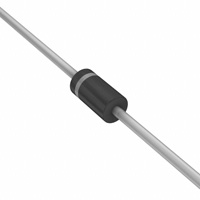
封装信息:
- 外壳:模塑塑料环氧树脂,UL 94V-0级阻燃
- 极性:色环表示阴极端,引线长度在5磅(2.3公斤)张力下
- 高温焊接保证:260℃/10秒/0.375英寸(9.5毫米)引线
- 重量:0.34克
- 尺寸:英寸和毫米
- 最大额定值和电气特性:在25°C环境温度下,单相半波60Hz,阻性或感性负载。对于电容性负载,电流降低20%。