0
登录后你可以
  • 下载海量资料
  • 学习在线课程
  • 观看技术视频
  • 写文章/发帖/加入社区
会员中心
创作中心
发布
  • 发文章

  • 发资料

  • 发帖

  • 提问

  • 发视频

创作活动
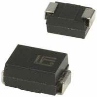
SMBJ28

SMBJ28

  • 厂商:

    TSC

  • 封装:

  • 描述:

    SMBJ28 - Surface Mount Transient Voltage Suppressor - Taiwan Semiconductor Company, Ltd

  • 数据手册
  • 价格&库存
SMBJ28 数据手册
SMBJ SERIES Surface Mount Transient Voltage Suppressor Voltage Range 5.0 to 170 Volts 600 Watts Peak Power Features For surface mounted application Low profile package Built-in strain relief Glass passivated junction Excellent clamping capability Fast response time: Typically less than 1.0ps from 0 volt to BV min. Typical IR less than 1μA above 10V High temperature soldering guaranteed: 260OC / 10 seconds at terminals Plastic material used carries Underwriters Laboratory Flammability Classification 94V-0 600 watts peak pulse power capability with a 10 x 1000 us waveform by 0.01% duty cycle .082(2.08) .076(1.93) SMB/DO-214AA .147(3.73) .137(3.48) .187(4.75) .167(4.25) .012(.31) .006(.15) .103(2.61) .078(1.99) .012(.31) .006(.15) .056(1.41) .035(0.90) .208(5.28) .200(5.08) .008(.20) .004(.10) Mechanical Data Case: Molded plastic Terminals: Solder plated Polarity: Indicated by cathode bandexcept bipolar Standard packaging: 12mm tape (EIA STD RS-481) Weight: 0.093gram Dimensions in inches and (millimeters) Maximum Ratings and Electrical Characteristics Rating at 25℃ambient temperature unless otherwise specified. Type Number Peak Power Dissipation at TA=25 C, Tp=1ms(Note O Symbol PPK Pd IFSM VF RθJL RθJA TJ, TSTG Value Minimum 600 3 100 3.5 / 5.0 10 55 -65 to + 150 O Units Watts Watts Amps Volts ℃/W O 1) Steady State Power Dissipation Peak Forward Surge Current, 8.3 ms Single Half Sine-wave Superimposed on Rated Load (JEDEC method) (Note 2, 3) - Unidirectional Only Maximum Instantaneous Forward Voltage at 50.0A for Unidirectional Only (Note 4) Typical Thermal Resistance (Note 5) Operating and Storage Temperature Range C Notes: 1. Non-repetitive Current Pulse Per Fig. 3 and Derated above TA=25 C Per Fig. 2. 2. Mounted on 0.4 x 0.4" (10 x 10mm) Copper Pads to Each Terminal. 3. 8.3ms Single Half Sine-wave or Equivalent Square Wave, Duty Cycle=4 pulses Per Minute Maximum. 4. VF=3.5V on SMBJ5.0 thru SMBJ90 Devices and VF=5.0V on SMBJ100 thru SMBJ170 Devices. 5. Measured on P.C.B. with 0.27” x 0.27” (7.0mm x 7.0mm) Copper Pad Areas. Devices for Bipolar Applications 1. For Bidrectional Use C or CA Suffix for Types SMBJ5.0 through Types SMBJ170. 2. Electrical Characteristics Apply in Both Directions. - 602 - RATINGS AND CHARACTERISTIC CURVES (SMBJ SERIES) FIG.1- PEAK PULSE POWER RATING CURVE NON-REPETITIVE PULSE WAVEFORM SHOWN in FIG. 3 TA=250C FIG.2- PULSE DERATING CURVE PEAK PULSE POWER (Pppm) or CURRENT (lpp) DERATING IN PERCENTAGE, % 100 100 Pppm, PEAK PULSE POWER, KW 75 10 50 1 25 0.2" sq 5.0mm2 COPPER PAD AREAS 0.1 0.1 s 1.0 s 10 s 100 s 1.0ms 10ms 0 0 25 50 75 100 125 O 150 175 200 td. PULSE WIDTH, sec. TA, AMBIENT TEMPERATURE. C FIG.3- PULSE WAVEFORM 150 FIG.4- MAXIMUM NON-REPETITIVE FORWARD SURGE CURRENT PEAK FORWARD SURGE CURRENT. (A) 200 8.3ms Single Half Sine Wave JEDEC Method UNIDIRECTIONAL ONLY lppm, PEAK PULSE CURRENT % IRSM PULSE WIDTH (td) is DEFINED tr=10 sec. AS THE POINT WHERE THE PEAK CURRENT DECAYS to 50% of lppm 100 100 PEAK VALUE lppm HALF VALUE- lpp 2 50 10/1000 sec. WAVEFORM AS DEFINED BY R.E.A. 0 0 td 10 1.0 2.0 t, TIME, ms 3.0 4.0 1 10 NUMBER OF CYCLES AT 60Hz 100 FIG.5- TYPICAL JUNCTION CAPACITANCE 6000 Tj=25 0C f=1.0MHz Vsig=50mVp-p MEASURED AT ZERO BIAS 1000 Cj, JUNCTION CAPACITANCE, pF 100 VR MEASURED AT STAND-OFF VOLTAGE,VWM 10 1 2 10 20 100 200 VWM, REVERSE STAND-OFF VOLTAGE. (V) - 603 - ELECTRICAL CHARACTERISTICS (TA=25OC unless otherwise noted) Device Device Marking code KD KE KF KG KH KK KL KM KN KP KQ KR KS KT KU KV KW KX KY KZ LD LE LF LG LH LK LL LM LN LP LQ LR LS LT LU LV LW LX LY LZ MD ME MF MG MH MK ML MM MN MP MQ MR MS MT MU MV MW MX MY MZ ND NE NF NG NH NK NL NM NN NP NQ NR NS NT NU NV NW NX NY NZ PD PE PF PG PH PK PL PM PN PP PQ PR Breakdown Voltage VBR (Volts) (Note 1) Min Max 6.40 6.40 6.67 6.67 7.22 7.22 7.78 7.78 8.33 8.33 8.89 8.89 9.44 9.44 10.0 10.0 11.1 11.1 12.2 12.2 13.3 13.3 14.4 14.4 15.6 15.6 16.7 16.7 17.8 17.8 18.9 18.9 20.0 20.0 22.2 22.2 24.4 24.4 26.7 26.7 28.9 28.9 31.1 31.1 33.3 33.3 36.7 36.7 40.0 40.0 44.4 44.4 47.8 47.8 50.0 50.0 53.3 53.3 56.7 56.7 60.0 60.0 64.4 64.4 66.7 66.7 71.1 71.1 77.8 77.8 83.3 83.3 86.7 86.7 94.4 94.4 100 100 111 111 122 122 133 133 144 144 167 167 178 178 189 189 7.30 7.00 8.15 7.37 8.82 7.98 9.51 8.60 10.3 9.21 10.9 9.83 11.5 10.4 12.2 11.1 13.6 12.3 14.9 13.5 16.3 14.7 17.6 15.9 19.1 17.2 20.4 18.5 21.8 19.7 23.1 20.9 24.4 22.1 27.1 24.5 29.8 26.9 32.6 29.5 35.3 31.9 38.0 34.4 40.7 36.8 44.9 40.6 48.9 44.2 54.3 49.1 58.4 52.8 61.1 55.3 65.1 58.9 69.3 62.7 73.3 66.3 78.7 71.2 81.5 73.7 86.9 78.6 95.1 86.0 102 92.1 106 95.8 115 104 122 111 136 123 149 135 163 147 176 159 204 185 218 197 231 209 Test Current @IT(mA) 10 10 10 10 10 10 10 10 1.0 1.0 1.0 1.0 1.0 1.0 1.0 1.0 1.0 1.0 1.0 1.0 1.0 1.0 1.0 1.0 1.0 1.0 1.0 1.0 1.0 1.0 1.0 1.0 1.0 1.0 1.0 1.0 1.0 1.0 1.0 1.0 1.0 1.0 1.0 1.0 1.0 1.0 1.0 1.0 1.0 1.0 1.0 1.0 1.0 1.0 1.0 1.0 1.0 1.0 1.0 1.0 1.0 1.0 1.0 1.0 1.0 1.0 1.0 1.0 1.0 1.0 1.0 1.0 1.0 1.0 1.0 1.0 1.0 1.0 1.0 1.0 1.0 1.0 1.0 1.0 1.0 1.0 1.0 1.0 1.0 1.0 1.0 1.0 Stand-Off Voltage VWM (Volts) 5.0 5.0 6.0 6.0 6.5 6.5 7.0 7.0 7.5 7.5 8.0 8.0 8.5 8.5 9.0 9.0 10 10 11 11 12 12 13 13 14 14 15 15 16 16 17 17 18 18 20 20 22 22 24 24 26 26 28 28 30 30 33 33 36 36 40 40 43 43 45 45 48 48 51 51 54 54 58 58 60 60 64 64 70 70 75 75 78 78 85 85 90 90 100 100 110 110 120 120 130 130 150 150 160 160 170 170 Maximum Maximum Maximum Reverse Leakage Peak Surge Clamping at Vwm Current IPPM Voltage at IPPM ID (uA) (Note 2)(Amps) VC(Volts) 800.0 800.0 800.0 800.0 500.0 500.0 200.0 200.0 100.0 100.0 50.0 50.0 20.0 20.0 10.0 10.0 5.0 5.0 5.0 5.0 5.0 5.0 5.0 5.0 5.0 5.0 5.0 5.0 5.0 5.0 5.0 5.0 5.0 5.0 5.0 5.0 5.0 5.0 5.0 5.0 5.0 5.0 5.0 5.0 5.0 5.0 5.0 5.0 5.0 5.0 5.0 5.0 5.0 5.0 5.0 5.0 5.0 5.0 5.0 5.0 5.0 5.0 5.0 5.0 5.0 5.0 5.0 5.0 5.0 5.0 5.0 5.0 5.0 5.0 5.0 5.0 5.0 5.0 5.0 5.0 5.0 5.0 5.0 5.0 5.0 5.0 5.0 5.0 5.0 5.0 5.0 5.0 65 68 55 61 51 56 47 52 44 48 42 46 39 43 37 40 33 37 31 34 28 31 26 29 24.4 27 23.1 25.1 21.8 24.2 20.0 22.8 19.5 21.5 17.6 19.4 15.0 17.7 14.6 16.0 13.5 14.9 12.6 13.8 11.7 13.0 10.6 11.8 9.8 10.8 8.8 9.7 8.2 9.0 7.8 8.6 7.3 8.1 6.9 7.6 6.5 7.2 6.1 6.7 5.8 6.5 5.5 6.1 5.0 5.5 4.7 5.2 4.5 5.0 4.1 4.6 3.9 4.3 3.5 3.8 3.2 3.5 2.9 3.2 2.7 3.0 2.3 2.5 2.2 2.4 2.0 2.2 9.6 9.2 11.4 10.3 12.3 11.2 13.3 12.0 14.3 12.9 15.0 13.6 15.9 14.4 16.9 15.4 18.8 17.0 20.1 18.2 22.0 19.9 23.8 21.5 25.8 23.2 26.9 24.4 28.8 26.0 30.5 27.6 32.2 29.2 35.8 32.4 39.4 35.5 43.0 38.9 46.6 42.1 50.0 45.4 53.5 48.4 59.0 53.3 64.3 58.1 71.4 64.5 76.7 69.4 80.3 72.7 85.5 77.4 91.1 82.4 96.3 87.1 103 93.6 107 96.8 114 103 125 113 134 121 139 126 151 137 160 146 179 162 196 177 214 193 231 209 268 243 287 259 304 275 SMBJ5.0 SMBJ5.0A SMBJ6.0 SMBJ6.0A SMBJ6.5 SMBJ6.5A SMBJ7.0 SMBJ7.0A SMBJ7.5 SMBJ7.5A SMBJ8.0 SMBJ8.0A SMBJ8.5 SMBJ8.5A SMBJ9.0 SMBJ9.0A SMBJ10 SMBJ10A SMBJ11 SMBJ11A SMBJ12 SMBJ12A SMBJ13 SMBJ13A SMBJ14 SMBJ14A SMBJ15 SMBJ15A SMBJ16 SMBJ16A SMBJ17 SMBJ17A SMBJ18 SMBJ18A SMBJ20 SMBJ20A SMBJ22 SMBJ22A SMBJ24 SMBJ24A SMBJ26 SMBJ26A SMBJ28 SMBJ28A SMBJ30 SMBJ30A SMBJ33 SMBJ33A SMBJ36 SMBJ36A SMBJ40 SMBJ40A SMBJ43 SMBJ43A SMBJ45 SMBJ45A SMBJ48 SMBJ48A SMBJ51 SMBJ51A SMBJ54 SMBJ54A SMBJ58 SMBJ58A SMBJ60 SMBJ60A SMBJ64 SMBJ64A SMBJ70 SMBJ70A SMBJ75 SMBJ75A SMBJ78 SMBJ78A SMBJ85 SMBJ85A SMBJ90 SMBJ90A SMBJ100 SMBJ100A SMBJ110 SMBJ110A SMBJ120 SMBJ120A SMBJ130 SMBJ130A SMBJ150 SMBJ150A SMBJ160 SMBJ160A SMBJ170 SMBJ170A Note: Notes: 1. VBR measured after IT applied for 300us, IT=square wave pulse or equivatent. 2. Surge current waveform per Figure 3 and derate per Figure 2. 3. All terms and symbols are consistant with ANSI/IEEE C62.35. 4. For bidirectional use C or CA suffix for types SMBJ5.0 thorugh types SMBJ170. 5. For bipolar types having VWM of 10 volts(SMBJ8.0C) and under the ID limit is doubled. - 604 - TVS APPLICATION NOTES: Transient Voltage Suppressors may be used at various points in a circuit to provide various degrees of protection. The following is a typical linear power supply with transient voltage suppressor units placed at different points. All provide protection of the load. FIGURE 1 Transient Voltage Suppressors 1 provides maximum protection. However, the system will probably require replacement of the line fuse(F) since it provides a dominant portion of the series impedance when a surge is encountered. However, we do not recommend to use the TVS diode here, unless we can know the electric circuit impedance and the magnitude of surge rushed into the circuit. Otherwise the TVS diode is easy to be destroyed by voltage surge. Transient Voltage Suppressor 2 provides execllent protection of circuitry excluding the transformer(T). However, since the transformer is a large part of the series impedance, the chance of the line fuse opening during the surge condition is reduced. Transient Voltage Suppressor 3 provides the load with complete protection. It uses a unidirectional Transient Voltage Suppressor, which is a cost advantage. The series impedance now includes the line fuse, transformer, and bridge rectifier(B) so failure of the line fuse is further reduced. If only Transient Voltage Suppressor 3 is in use, then the bridge rectifier is unprotected and would require a higher voltage and current rating to prevent failure by transients. Any combination of these three, or any one of these applications, will prevent damage to the load. This would require varying trade-offs in power supply protection versus maintenance(changing the time fuse). An additional method is to utilize the Transient Voltage Suppressor units as a controlled avalanche bridge. This reduces the parts count and incorporates the protection within the bridge rectifier. FIGURE 2 RECOMMENDED PAD SIZES The pad dimensions should be 0.010"(0.25mm) longer than the contact size, in the lead axis. This allows a solder fillet to form, see figure below. Contact factory for soldering methods. - 605 -
SMBJ28 价格&库存

很抱歉,暂时无法提供与“SMBJ28”相匹配的价格&库存,您可以联系我们找货

免费人工找货
SMBJ28A
  •  国内价格
  • 20+0.13365
  • 200+0.1254
  • 500+0.11715
  • 1000+0.1089
  • 3000+0.10478
  • 6000+0.099

库存:131

SMBJ28A
    •  国内价格
    • 10+0.25025
    • 50+0.23285
    • 200+0.21835
    • 600+0.20385
    • 1500+0.19225
    • 3000+0.185

    库存:2552

    SMBJ28A
    •  国内价格
    • 1+0.16537
    • 10+0.15881
    • 100+0.14306
    • 500+0.13519

    库存:2405

    SMBJ28A
    •  国内价格
    • 1+0.1953
    • 10+0.18755
    • 100+0.16895
    • 500+0.15965

    库存:1422

    SMBJ28A
      •  国内价格
      • 1+0.20439
      • 30+0.19709
      • 100+0.18979
      • 500+0.1752
      • 1000+0.1679
      • 2000+0.16352

      库存:990

      SMBJ28A
        •  国内价格
        • 5+0.5794
        • 20+0.52913
        • 100+0.47885
        • 500+0.42857
        • 1000+0.40511
        • 2000+0.38835

        库存:1358

        SMBJ28CA
        •  国内价格
        • 1+0.12084
        • 10+0.11204
        • 30+0.11028
        • 100+0.105

        库存:15

        SMBJ28CA
          •  国内价格
          • 5+0.23578
          • 20+0.21497
          • 100+0.19417
          • 500+0.17336
          • 1000+0.16366
          • 2000+0.15673

          库存:2888

          SMBJ28A
          •  国内价格
          • 20+0.23115
          • 200+0.21543
          • 600+0.19971
          • 3000+0.184

          库存:3302

          SMBJ28A
            •  国内价格
            • 1+0.22162
            • 10+0.20332
            • 30+0.19966

            库存:891