USER GUIDE | UG:501
Development Kit User Guide
Mike DeGaetano
Applications Engineering
November 2015
Contents Page
Features 1
Introduction 1
System Overview
2
Front-End (FE) Chassis
2
Hold-up Bank (HUB)
3
Point-of-Load (PoL)
Chassis
Set-up Instructions
3
Bill of Materials
5
3
Features
n From bulk power distribution to Point-of-Load in two simple steps
n Universal AC input
n Multiplicity of Point-of-Load options
n Small size, low profile, easy-to-use, highly flexible
IMPORTANT NOTICE:
Please read this user guide before operating the Vicor Development Kit.
The Development Kit is for evaluation purposes only. Compliance testing on the
Development Kit is not permissible.
Introduction
The Vicor Development Kit contains a Front-End (FE) Chassis, a Hold-up Bank (HUB),
and a Point-of-Load (PoL) Chassis. The Front End Chassis has chassis mount versions
of the AIM in a VIA package and PFM in a VIA package that may be connected to
worldwide AC mains. A HUB is included to provide proper holdup for the PFM.
The PoL Chassis has an Input Board and three Picor Cool-Power ZVS Buck Regulator
evaluation boards. The Input Board interfaces with the Front End Chassis and HUB to
provide a 24 V or 48 V voltage rail on the PoL Chassis. The included Picor regulators
provide 3.3 V, 5 V, and 12 V outputs.
Please visit www.vicorpower.com for datasheets and more information on the individual
products used in the Development Kit. Part numbers can be found in the Bill of
Materials on Page 5.
UG:501
vicorpower.com
Applications Engineering: 800 927.9474
Page 1
�
DANGER! HIGH VOLTAGE!
DANGER! HOT SURFACE!
The Development Kit contains exposed hazardous voltages on the Front-End Chassis.
The Front-End Chassis may be operating at surface temperatures which may pose a
thermal hazard to the operator. Please use caution not to touch the Front-End Chassis
unless the power is disconnected and the Front-End Chassis has been given sufficient
time to cool.
IMPORTANT NOTICE:
AC Input Fusing
The Vicor Development Kit is meant for bench evaluation purposes only.
A power supply with an adjustable current limit must be used when powering the
Development Kit.
Although a 7A input fuse is installed in the AC cord adapter, this fuse does not meet
safety approvals outlined for the AIM and PFM. It is the user’s responsibility to select
proper fusing at the system level to meet the desired application requirements.
Please refer to the section titled Input Fuse Selection on page 16 in the PFM data
sheet for guidelines on proper fuse selection.
System Overview
Front-End (FE) Chassis
Figure 1.
Front-End Chassis
Vicor AIM and PFM in a VIA package chassis mount modules are mounted on the
Front-End Chassis of the Development Kit. The AIM interfaces directly with worldwide
AC mains and provides a rectified AC input for the PFM. The AIM combines a bridge
rectifier, EMI filter, and surge protection circuitry in an easy to use VIA plastic housing.
The PFM in a VIA package is a 400 W power factor corrected AC-DC converter operating
from a rectified universal AC input which delivers an isolated and regulated Safety
Extra-Low Voltage (SELV) 24 V or 48 V (model dependent) secondary output.
These modules are mounted on the Front End Chassis of the Development Kit to
showcase their efficient, simple, and cost effective AC-DC solution compliant to IEC
61000-3-2 Class B EMC standard. The metallic stand acts as a heat sink for the AIM
and PFM. Please use caution not to touch the Front End chassis unless the power is
disconnected and the front end chassis has been given sufficient time to cool.
UG:501
vicorpower.com
Applications Engineering: 800 927.9474
Page 2
�Hold-up Bank (HUB)
The PFM uses secondary-side energy storage to maintain output hold up through line
dropouts and brownouts. A hold-up capacitor bank is included in the kit to achieve the
required hold up functionality. Moreover, the HUB provides a viable path for the second
harmonic due to the PFM power factor correction function.
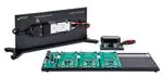
Point-of-Load (PoL) Chassis
Figure 2.
PoL Chassis
Point-of-Load evaluation boards are on mounted on the PoL Chassis and have 3.3 V,
5 V, and 12 V outputs. The Input Board, on the left side of the PoL Chassis, interfaces
with the Front-End Chassis and HUB using the three black right angle connectors. The
PoL Chassis showcases Vicor’s high power density, flexible, and high-efficiency
Point-of-Load offerings.
A communications port is available on the Input Board which can be connected to the
VIA module mounted on the Front-End Chassis.
Note: This feature will be available in the future.
I2C communications will be available in the future for VOUT margining, fault reporting,
and EN pin polarity for the Picor converters.
Set-up Instructions
Figure 3.
Front-End Chassis Set Up
UG:501
vicorpower.com
Applications Engineering: 800 927.9474
Page 3
�Figure 4.
PoL Chassis Setup
1.
Ensure the evaluation boards on the PoL Chassis are securely plugged into the white
plastic board-to-board edge connectors and that all nuts on the evaluation boards
are screwed down. The toggle switches on the evaluation boards control the enable
for each PoL converter.
Note: Any load connected to the PoL converters should be off or disabled until the Front-End
Chassis has been powered on.
2. Connect the red and black HUB cable to one of the black right angle connectors on
the Input Board of the PoL Chassis. Input Board is labeled 2 in Figure 4.
3. Remove black plastic cable retainer on the Front-End Chassis, labeled 8 in Figure 3,
and the plastic insert that is screwed down on the AIM input. The plastic insert can
be discarded.
4.
Insert provided AC cord into the cord retainer. The AC cord should be fed through
the retainer to the location where the black insulation ends and the Line, Neutral,
and Ground wires are exposed. Screw retainer back to the Front-End Chassis and
screw down the Ground wire ring lug using the screw hole below the retainer as
seen in Figure 3. Install the Line/Black wire to the top terminal of the AIM and
install the Neutral/White wire to the bottom terminal of the AIM.
5. Ensure all screws are secure on the Front-End Chassis.
6. Plug in the red and black Front-End Chassis output cable, labeled 11 in Figure 3, to
one of the black right angle connectors on the Input Board of the PoL Chassis.
7.
Connect the outputs of the PCBs on the PoL Chassis to the desired load(s) via the
large screw-down output connectors. Test points are available near the top of each
PoL PCB to observe the output voltage from the Front-End chassis, and test points
between the output connectors are available to observe the output voltage from the
PoL converter.
8. Connect the AC cord to a bench power supply.
9. Once power has been applied to the Front-End Chassis, the load(s) connected to
PoL Chassis can be enabled.
UG:501
vicorpower.com
Applications Engineering: 800 927.9474
Page 4
�Bill of Materials
Table 1.
Hardware Bill of Materials
common to all Development Kits
Description
Manufacturer
Manufacturer
Part Number
M3.5 X 14 SSTL PH PHILLIPS SCREW
Fastenal
0145078
M3.5x8 SSTL PH PHILLIPS SCREW, BLACK
Fastenal
0145082
CLAMP .375 PA66 BLACK .250 BUNDLE DIA
HellermannTyton
T3D02500M4
CLAMP .375 PA66 BLACK .375 BUNDLE DIA
HellermannTyton
T3D03750M4
AC LINE CORD KIT
Quail Electronics
2573.048S
UNIVERSAL AC ADAPTER TO UK
Quail Electronics
0522.B
UNIVERSAL AC ADAPTER TO EURO SCHUKO
Quail Electronics
0521.B
INTERCONNECT TO POL ASSEMBLY
Vicor
42982
TIM PAD, VIA, 4414PFM
Vicor
43151
TIM PAD, VIA, 1714
Vicor
43150
M4x12 SSTL HEX HEAD CAP SCREW
McMaster-Carr
91287A113
SPACER, 8 mm OD, 4.2 mm ID, 2.5 mm HT
Vicor
42603
M4 SSTL THIN HEX NUT
McMaster-Carr
90710A035
10 Position Open Edge Board to Board Connector
AVX
9159010061916
Table 2.
Development Kit Bill of Materials
Development Kit
Part Number
DKIT-AC-24-POL-00
DKIT-AC-48-POL-00
Description
Front-End / PoL Chassis
Part Number
VIA package/PoL Converter or HUB Part Number
Front End Chassis
PFM4414EB6M24D0T00
AIM1714VB6MC7D5T00
PFM4414VB6M24D0T00
HUB30-24
PoL Chassis
PI33-24-3-5-12-00
PI3301-00-EVAL2
PI3302-00-EVAL2
PI3303-00-EVAL2
Front End Chassis
PFM4414EB6M48D0T00
AIM1714VB6MC7D5T00
PFM4414VB6M48D0T00
HUB13-48
PoL Chassis
PI35-48-3-5-12-00
PI3543-00-EVAL2
PI3545-00-EVAL2
PI3546-00-EVAL2
The Power Behind Performance
Rev 1.1
12/15
vicorpower.com
Applications Engineering: 800 927.9474
Page 5
�