USER GUIDE | UG:312
QPI-12-CB1-EVAL
QPI-12LZ Filter Carrier Board for 48V VI Chip® EMI Evaluation
Contents Page
Introduction 1
Bill of Materials
2
Board Assembly
3
EMI Bypass Configurations
4
EMI Performance and
Test Set Up
4
Ordering Information
7
Introduction
The QPI-12-CB1 carrier board is an evaluation board platform designed to demonstrate the EMI
capabilities of a QPI-12LZ filter, with any combination of 48V input PRM™ / VTM™ or BCM® evaluation
boards. The QPI-12-CB1 board includes a pre-mounted filter along with some additional components
necessary to demonstrate the full functionality of the filter, along with mounting areas for VI Chip
evaluation boards. This user guide provides basic instructions for assembly and use of the board. Further
information on the functionality of the VI Chip boards, as well as the QPI-12LZ can be found in the
VI Chip Evaluation Board user guide as well as the VI Chip and QPI-12LZ data sheets.
QPI-12LZ Product Description
The QPI-12LZ EMI filter is specifically designed to attenuate conducted common-mode (CM) and
differential-mode (DM) noise of Vicor VI Chip products to comply with the CISPR22 standard
requirements for conducted noise measurements. The filter is designed to operate up to 80VDC
continuous, with a 100VDC surge for 100ms, and supports 7A loads up to 60°C without derating.
Designed for the telecom bus range, the VI Chip EMI Filter supports the PICMG® 3.0 specification for
filtering system boards to the EN55022 Class B limits.
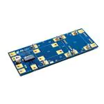
Figure 1
QPI-12-CB1 carrier board
featuring the QPI-12LZ EMI filter
UG:312
Page 1
�Figure 2
QPI-12-CB1 board overview
Bill of Materials
Reference Designator
Description
QPI
QPI-12LZ SiP
CI
Capacitor, electrolytic, 47µF, 100V
C2
Capacitor, ceramic, 2.2µF, 100V
CY5 – CY10
Capacitor, X7R ceramic, 4.7nF, 1,000V
Hardware
Machine screw, pan head, 0.373in, 1/2in long, #10-24 thread
Hardware
Machine nut, hex, 3/8in, #10-24 thread
CY1 – CY4
Optional Y-Cap configuration (not populated)
Figure 3
QPI-12-CB1
carrier board schematic
1
VTM_IN+
2
JBCM+
3
1
VTM_OUT+
As noted above: CY1 thru CY4 not populated.
2
C1
47µF
VIN–
VIN–
VIN–A
JVIN–
Shield
1
8 BUS+
9 BUS+
EMI+ 7
EMI+ 6
10 BUS–
1 BUS–
EMI– 5
EMI– 4
SHIELD
C2
2.2µF
+IN
Shield
1
2
3
4
–IN
CY5
4.7nF
2
CY8
4.7nF
Carrier
QPI-12LZ
SHIELD
VIN+
VIN+
CY7
4.7nF
4.7nF
2
VIN+A
JVOUT+
3
VTM_IN+
CY3
1
3
JVIN+
2
CY6
4.7nF
PRM+
VTM_IN+ 5
BCM+
VTM_OUT+ 6
VTM_OUT– 7
BCM–
PRM–
VTM_IN–
CY1
4.7nF
CY2
4.7nF
8
CY9
4.7nF
CY4
4.7nF
VTM_OUT+
VOUT+
VOUT–
VTM_OUT–
CY10
4.7nF
VTM_IN–
1
VTM_OUT–
2
3
JVOUT–
1
VTM_IN–
UG:312
2
3
JBCM–
Page 2
�Board Assembly
The VI Chip® evaluation boards should be attached to the carrier board using the hardware provided.
Begin by removing the top nuts from the bolts in the space provided for mounting the evaluation board.
Check to see that the lower bolts are tightened. Remove rubber spacers from the VI Chip evaluation
board(s). Place the VI Chip evaluation board on the bolts. Make sure that the evaluation board is placed
in the proper input to output orientation with respect to the carrier board (the input side will have the
capacitor). Replace the top nuts and tighten gently with a wrench. Attach input and output leads, be
careful to confirm proper polarity before powering up.
When using the carrier board, pay special attention to the wiring and grounding. Wires should be kept
as short as possible and positioned to minimize radiated noise pick up on the QPI-12LZ.
Figure 4
Side-view hardware assembly
Figure 5
QPI-12-CB1 carrier board
assembled with PRM™ and
VTM™ evaluation boards
Figure 6
QPI-12-CB1 carrier board
assembled with a BCM®
evaluation board
UG:312
Page 3
�EMI Bypass Configurations
EMI bypass capacitors (“Y” capacitors) are an essential element in a switch-mode DC-DC filter
application as these capacitors provide a return path for common-mode noise currents to their source;
so careful attention to bypass capacitor implementation is essential for a successful EMI filter design.
This carrier board is preconfigured in a “baseplate” EMI topology, which uses six “Y” capacitors (only
four are actually used in a BCM® configuration), as illustrated in Figure 7 below. This is the preferred
topology for VI Chip® applications. The carrier board can be manually reconfigured to an “open frame”
topology, which uses four “Y” caps in a PRM™ / VTM™ combination (two for a BCM), as shown
in Figure 8. The open-frame approach may attenuate certain load dependent noise better than the
baseplate method. The carrier board provides an ideal test vehicle for making a comparison between
the two “Y” capacitor configurations. To reconfigure to “open frame” carefully remove capacitors CY5
through CY10 and place four of those six capacitors in the positions marked as CY1 through CY4.
EMI Performance and Test Set Up
The EMI plots in Figures 9 through 14 are the total noise measurements, on both the positive and
negative lines of the QPI-12LZ with various VI Chip® configurations, using the basic baseplate standard
“Y” cap configuration. Figure 7 shows the basic EMI measurement set up that was used to achieve
these results. Figure 8 shows the alternate set up method when converting to the open-frame approach.
In Figure 7 (baseplate method), capacitors CY5 through CY10 represent the recirculation capacitors that
are connected to each of the four input and output terminals, then are commoned to a shield plane
that has been created underneath the converter. Since the PRM / VTM pair is similar to a conventional
converter, which is split into to halves, two additional “Y” caps (CY7 and CY9) were added to the PRM’s
output (the input to the VTM), referenced to the shield plane.
In Figure 8 (open-frame method), four “Y” capacitors are used (CY1 through CY4) rather than the
two “Y” caps that a conventional converter would require, once again because of the topology split
created by the pair.
In a BCM application there is no topology split so the set up would require two fewer capacitors for
either configuration. The open-frame method would only need one pair of input an output caps,
referenced to the shield plane on either side of the BCM. And for open-frame method a pair of “Y”
caps across the positive input to positive output, and negative input and negative output would
be sufficient.
Figure 7
Basic EMI measurement set up
for “baseplate” configuration
Shielded Box
~1.25m
PCB Board
PCB Plane Under Converter
BUS+
LISN
QPI+
VIN+
VOUT+
VIN+
VOUT+
C1
BUS
SUPPLY
QPI
47µF
SHIELD
BUS–
LISN
PRM
QPI–
VIN–
CY5
VTM
VOUT–
CY6
VIN–
CY9
VOUT–
CY7
CY10
CY8
Shield Plane (Earth Ground)
Figure 8
Basic EMI measurement set up
for “open-frame” configuration
Shielded Box
~1.25m
CY3
PCB Board
BUS+
LISN
QPI+
VIN+
VOUT+
CY1
VIN+
VOUT+
C1
BUS
SUPPLY
QPI
47µF
SHIELD
BUS–
LISN
PRM
QPI–
VIN–
VOUT–
CY4
VTM
VIN–
PCB Plane
Under Converter
VOUT–
CY2
Shield Plane (Earth Ground)
UG:312
Page 4
�Figure 9
Total noise QPI-12LZ [a] with
48V input PRM™ and
3V output VTM™;
3.27A input current;
160W output load
Figure 10
Total noise QPI-12LZ [a] with
48V input PRM and
12V output VTM;
4.03A input current;
180W output load
Figure 11
Total noise QPI-12LZ [a] with
48V input PRM and
48V output VTM;
3.45A input current;
160W output load
[a]
These EMI plots are actually based on QPI-10LZ, which includes the same filter elements but includes integrated
hot swap.
UG:312
Page 5
�Figure 12
Total noise QPI-12LZ [a] with
48V input, 3V output BCM®;
3.18A input current;
160W output load
Figure 13
Total noise QPI-12LZ [a] with
48V input, 12V output BCM;
3.75A input current;
180W output load
Figure 14
Total noise QPI-12LZ [a] with
48V input, 48V output BCM;
3.20A input current;
153W output load
[a]
These EMI plots are actually based on QPI-10LZ, which includes the same filter elements but includes integrated
hot swap.
UG:312
Page 6
�4.585
2.435
0.000
Figure 15
Mechanical drawing
for QPI-12-CB1
3.200
3.200
+IN
C1
BCM
QPI-12LZ
0.400
CY6
Plane CY4
–IN
5/07 revC
Carrier
CY9
VOUT–
CY10
2.350
2.150
1.950
1.250
1.050
0.850
0.385
CY2
0.000
2.500
0.850
0.250
VOUT–
SHIELD
VIN–
0.000
VOUT+
–IN
VIN–
0.000
BCM+
VTM
BCM-
PRM
7.200
1.050
0.850
0.650
+IN
7.950
VIN+
C2
2.815
CY8
VOUT+
5.600
VIN+
2.250
2.150
2.050
CY7
CY5
QPI / VIChip Carrier Board
For QPI-11 or QPI-12 filter models
Reorder # QPI-xx-CB1*
* xx indicates model
5.100
2.800
CY1
CY3
Ordering Information
Carrier Board Part Number
Compatible VI Chip® Evaluation Boards (sold separately) [b]
PRMs™:
P048F048T12AL-CB
P048F048T24AL-CB
P048F048T17AL-CB
P048F048T32AL-CB
QPI-12-CB1
VTMs™: All 48V input models
BCMs®: All 48V input models
[b]
Some VI Chip products exceed the current rating and therefore may not be compatible when operating at
full load.
Additional Resources
nn
QPI-12LZ Data Sheet
nn
Compatible VI Chip® Converters
nnPRM and VTM
nnBCM
UG:312
Page 7
�Limitation of Warranties
Information in this document is believed to be accurate and reliable. HOWEVER, THIS INFORMATION
IS PROVIDED “AS IS” AND WITHOUT ANY WARRANTIES, EXPRESSED OR IMPLIED, AS TO THE
ACCURACY OR COMPLETENESS OF SUCH INFORMATION. VICOR SHALL HAVE NO LIABILITY FOR THE
CONSEQUENCES OF USE OF SUCH INFORMATION. IN NO EVENT SHALL VICOR BE LIABLE FOR ANY
INDIRECT, INCIDENTAL, PUNITIVE, SPECIAL OR CONSEQUENTIAL DAMAGES (INCLUDING, WITHOUT
LIMITATION, LOST PROFITS OR SAVINGS, BUSINESS INTERRUPTION, COSTS RELATED TO THE REMOVAL
OR REPLACEMENT OF ANY PRODUCTS OR REWORK CHARGES).
Vicor reserves the right to make changes to information published in this document, at any time
and without notice. You should verify that this document and information is current. This document
supersedes and replaces all prior versions of this publication.
All guidance and content herein are for illustrative purposes only. Vicor makes no representation or
warranty that the products and/or services described herein will be suitable for the specified use without
further testing or modification. You are responsible for the design and operation of your applications
and products using Vicor products, and Vicor accepts no liability for any assistance with applications or
customer product design. It is your sole responsibility to determine whether the Vicor product is suitable
and fit for your applications and products, and to implement adequate design, testing and operating
safeguards for your planned application(s) and use(s).
VICOR PRODUCTS ARE NOT DESIGNED, AUTHORIZED OR WARRANTED FOR USE IN LIFE SUPPORT,
LIFE-CRITICAL OR SAFETY-CRITICAL SYSTEMS OR EQUIPMENT. VICOR PRODUCTS ARE NOT CERTIFIED
TO MEET ISO 13485 FOR USE IN MEDICAL EQUIPMENT NOR ISO/TS16949 FOR USE IN AUTOMOTIVE
APPLICATIONS OR OTHER SIMILAR MEDICAL AND AUTOMOTIVE STANDARDS. VICOR DISCLAIMS
ANY AND ALL LIABILITY FOR INCLUSION AND/OR USE OF VICOR PRODUCTS IN SUCH EQUIPMENT OR
APPLICATIONS AND THEREFORE SUCH INCLUSION AND/OR USE IS AT YOUR OWN RISK.
Terms of Sale
The purchase and sale of Vicor products is subject to the Vicor Corporation Terms and Conditions of Sale
which are available at: (http://www.vicorpower.com/termsconditionswarranty)
Export Control
This document as well as the item(s) described herein may be subject to export control regulations.
Export may require a prior authorization from U.S. export authorities.
Contact Us: http://www.vicorpower.com/contact-us
Vicor Corporation
25 Frontage Road
Andover, MA, USA 01810
Tel: 800-735-6200
Fax: 978-475-6715
www.vicorpower.com
email
Customer Service: custserv@vicorpower.com
Technical Support: apps@vicorpower.com
©2019 Vicor Corporation. All rights reserved. The Vicor name is a registered trademark of Vicor Corporation.
PICMG® is a trademark of the PICMG consortium.
All other trademarks, product names, logos and brands are property of their respective owners.
01/19
Rev 1.1
Page 8
�


 工商网监
湘ICP备2023018690号
工商网监
湘ICP备2023018690号
