USER GUIDE | UG:313
QPO-1-EVAL1
QPO™ Active Output Filter Evaluation Board
Contents Page
Introduction 1
Features 1
QPO-1-EVAL1 BOM
3
Installed Components
3
User Defined Components
3
Function Descriptions
4
Introduction
The QPO-1-EVAL1 is designed to allow full testing of the QPO-1LZ, along with its various performance
options, to fully optimize a final system design. The board offers two terminal options for vertical or
horizontal mounting. The user must select the required values for the RHR, RSCSET and RSA resistors
and solder them in the designated positions before applying power to the EVAL1. Please refer to
the QPO-1LZ product data sheet, schematics and the following pages for the proper application
of this board.
The QPO-1 output ripple attenuator SiP uses active filtering to reduce output ripple and noise (PARD)
over 30dB from 500Hz to 500kHz and can be extended down to 50Hz with additional capacitance
added to the VREF pin. The QPO-1LZ operates over a voltage range from 3 to 30VDC and supports load
currents as high as 10A. Output regulation is maintained with remote sense or trim adjustment of the
power supply. The closed loop architecture improves transient response and ensures quiet point-of-load
regulation when used in conjunction with the power supply’s control loop or trim node.
Slope Adjust
4
Headroom Adjust
4
SC Function
4
Remote Sense
4
Start-up Circuit
6
Features
Peak Detector
6
nn
> 30dB PARD attenuation, 1 – 500kHz
Ordering Information
8
nn
3 – 30VDC operating range
nn
10A rating
nn
Supports precise point-of-load regulation through use of remote sensing or converter trimming
nn
Optional start-up circuit included
nn
User-selectable performance optimization for attenuation, power dissipation and transient response
nn
Horizontal or vertical mounting options
nn
Evaluation board includes a Johnson Jack for low-noise measurement of the QPO’s
filtering performance
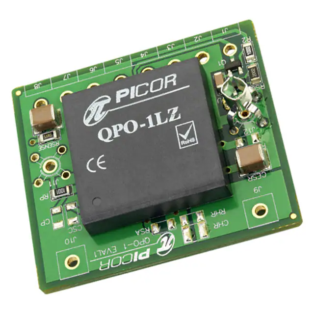
Figure 1
Top view of evaluation board
UG:313
Page 1
�QPO-1 Performance
The waveforms in Figure 2 highlight the QPO-1’s ability to both filter a converter’s output ripple
and maintain a constant output voltage during a load transient. The input voltage of the QPO-1
(dark blue) shows varying amplitude and frequency PARD before and during the load transient, but
the QPO-1 output voltage (light blue) remains relatively unaffected. The load transient is a 1 – 10A
load step (green).
The converter used is a Vicor Mini, 48V to 5V converter (Model number: V48B5C200BN).
Figure 2
PARD and Transient Attenuation
Figure 3
Evaluation board schematic
J11
J12
J8
C1
15µF
RSENSE
51.1
J7
J6
J5
J3
RP
RSA
1.00kΩ
J9
QPO OUT
Peak Det
CESR
SC Set
SC
TBD
CESR
RHR
CHR
CP
TBD
Opt
Opt
R2
DZ1
18V
100Ω
RSU
Q1
IRLML5103TRPBF
20.0kΩ
Gnd
CSU
1µF
J10
J6
Start-up Circuit
TBD
VREF
VREF Gnd
J2
15µF
RSCSET
Slope Adj
J1
J4
QPO IN
J1
UG:313
Page 2
�QPO-1-EVAL1 BOM
Qty
Description
Value
Designator
Vendor
2
Capacitor, X7R eramic,
15µF, 25V, 1812
15µF
C1, CESR
TDK
C4532X7R1E156MT
1
Capacitor, X7R Ceramic,
1µF, 50V, 1206
1µF
CSU
TDK
C3216X7R1H105K
1
Diode, Zener,
12V, 0.15W, SOT-23
18V
DZ1
ON Semi
8
Samtec, 0.2in,
Rt-Angle Header
J1, J2, J3, J4,
J5, J6, J7, J8
Samtec
2
Connector, Johnson Jack
Johnson Jack
Vendor Part Number
BZX84C18LT1G
FWS-08-02-T-S-RA
J11, J12
Tektronix
RLML5103TRPBF
Q1
International
Recifier
131503100
QPO-1LZ
QPO-1
VICOR
QPO-1LZ
F
1
Transistor, PFET, 30V, 0.6A
IRLML5103TRPB
1
QPO-1LZ
1
Resistor, 5%, 0.25W, 1206
100
R2
Rohm
MCR18EZPJ101
1
Resistor, 5%, 0.25W, 1206
1.00kΩ
RP
Rohm
MCR18EZHF1001
1
Resistor, 5%, 0.25W, 1206
51.1
RSENSE
Rohm
MCR18EZPF51R1
1
Resistor, 1%, 0.25W, 1206
20kΩ
RSU
Rohm
MCR18EZHF2002
Installed Components
The QPO-1-EVAL1 board comes with the following components pre-stuffed:
Remote Sense Components
C1, RSENSE
Start-up Assist Circuit
CSU, RSU, DZ1, R2, Q1
Peak Detector
RP
CESR CESR
User-Defined Components
The QPO-1-EVAL1 board comes with the following components not installed; values to be
determined by customer:
Headroom Resistor
RHR (not optional, must be installed for proper operation)
Headroom Capacitor
CHR (optional)
Slope Adjust
RSA (optional)
SC Function
CSC, RSCSET (optional)
Peak Detector
CP (optional)
UG:313
Page 3
�Function Descriptions
Slope Adjust
The slope adjust function allows the user to modify the voltage drop across the QPO-1 (headroom
voltage) dependent on the current passing through the QPO-1. This function is used to maintain
a constant power across the QPO-1 over a varying range of load currents. The RSA resistor can be
calculated by using the following equation:
RSA =
0.05V ∆ IOUT
∆V 2.5kΩ
A
HR
(1)
Where:
∆IOUT = Maximum change in load current (A)
∆VHR = headroom voltage change over load range (V)
RSA = slope adjust resistor (Ω)
The slope adjust feature can be disabled by either using a large resistor value (100kΩ or greater) for RSA
or by omitting this resistor entirely.
Headroom Adjust
The RHR resistor is used to program the desired voltage drop across the QPO-1. This voltage must be
greater than the ripple voltage that the QPO-1 is to filter, with additional voltage added for the voltage
drops in the attenuation path. Like the RP resistor, the RHR resistor must always be installed for proper
operation. The value of RHR can be calculated using this equation:
RHR =
QPOOUT 2.5kΩ
VHR
(2)
Where:
RHR = headroom setting resistor value (Ω)
QPOOUT = the voltage on the QPO’s output (V)
VHR = the target headroom voltage (V)
If this resistor is omitted, then the reference pin will be at the same voltage as the input pin, forcing the
output pin to be the same voltage as the input pin.
SC Function
The function of the SC circuit is to use a converter’s trim or SC (secondary control) pin to compensate
for the voltage drop across the QPO-1, thereby maintaining the desired output voltage on
the QPO’s output.
The RSCSET resistor (listed as RSC in the data sheet) determines the amount of current the SC pin of the
QPO-1 will source. The current is calculated by dividing the headroom voltage (the voltage drop from
QPOIN to QPOOUT ) by RSCSET.
RSCSET =
RIN � VOUT
VRPT
(3)
Where:
VOUT = nominal converter output voltage (V)
VRPT = internal reference voltage (V)
RIN = internal series resistor (Ω)
When using one of the Vicor Micro, Mini or Maxi converters, the RIN = 1kΩ and the VRPT = 1.23V.
Figure 4 shows the QPO-1-EVAL1 board connected so as to use the SC function to compensate for the
QPO-1’s voltage drop.
Remote Sense
Compensation for the QPO-1’s voltage drop can be done using the converter’s remote-sense pins, if
available. The on-board sensing network can be attached as is shown in Figure 5.
UG:313
Page 4
�Figure 4
Evaluation board in
SC configuration
–
–
QPO-1
US AND FOREIGN PATENTS, PATENTS PENDING
Figure 5
Evaluation board in
remote‑sense configuration
–
–
QPO-1
US AND FOREIGN PATENTS, PATENTS PENDING
UG:313
Page 5
�Figure 6
Start-up waveforms; without
(top) and with (bottom) the
optional start-up circuit
Start-up Circuit
The start-up circuit (Figure 3) on the evaluation board is used to connect the QPO-1’s reference pin to its
input pin during start up. In both waveform pictures of Figure 6, the Output Voltage (light blue) follows
the VREF voltage (purple) of the QPO-1.
In the picture on the top in Figure 6, without the optional start-up circuit, the QPO-1 input voltage (the
converter’s output voltage) can be seen to be greater than the nominal 5V output of the converter.
This is due to the QPO-1’s SC circuit having greater headroom voltage during start up and therefore
over‑driving the SC of the converter. After about 40ms, the VREF voltage reaches its 5V pre-set limit and
the converter’s output voltage starts to drop, eventually steadying out at 5.35V, the nominal output
voltage plus the QPO-1’s headroom voltage.
The potential problem with this start up is that the converter could fault due to its output being forced
to be greater than 110% of the nominal value. For converters with lower nominal output voltages, this
could be very serious condition.
The waveforms on the bottom are the same converter with the optional start-up circuit enabled. Here,
the VREF is forced to follow VIN, so VOUT follows as well. After about 25ms, the start-up circuit releases
the VREF pin and it adjusts it value down to generate the proper headroom voltage across the QPO-1.
Using this method, there is no possibility of over-driving the converter and causing a fault.
Peak Detector
The QPO-1 peak detector is used to adapt the headroom voltage in response to increasing converter
ripple. The greater the ripple on the QPO-1’s input, the greater the headroom voltage across the QPO-1.
This feature can be disabled by adding the CP capacitor to the evaluation board. The addition of this
capacitor creates an RC filter network that filters out the converter’s ripple to the peak detector.
The RP resistor must always be installed for proper operation. The peak detector creates the
internal reference voltage rail that gets divided down by the headroom resistor RHR.
UG:313
Page 6
�
UG:313
Page 7
QPO-1
US AND FOREIGN PATENTS, PATENTS PENDING
Figure 7
Mounting options
�Figure 8
Mechanical drawing
QPO-1
EVAL1
Ordering Information
Carrier Board Part Number
QPO-1-EVAL1
Compatible VI Chip® Evaluation Boards (sold separately) [b]
Evaluation Board for QPO-1L
UG:313
Page 8
�Limitation of Warranties
Information in this document is believed to be accurate and reliable. HOWEVER, THIS INFORMATION
IS PROVIDED “AS IS” AND WITHOUT ANY WARRANTIES, EXPRESSED OR IMPLIED, AS TO THE
ACCURACY OR COMPLETENESS OF SUCH INFORMATION. VICOR SHALL HAVE NO LIABILITY FOR THE
CONSEQUENCES OF USE OF SUCH INFORMATION. IN NO EVENT SHALL VICOR BE LIABLE FOR ANY
INDIRECT, INCIDENTAL, PUNITIVE, SPECIAL OR CONSEQUENTIAL DAMAGES (INCLUDING, WITHOUT
LIMITATION, LOST PROFITS OR SAVINGS, BUSINESS INTERRUPTION, COSTS RELATED TO THE REMOVAL
OR REPLACEMENT OF ANY PRODUCTS OR REWORK CHARGES).
Vicor reserves the right to make changes to information published in this document, at any time
and without notice. You should verify that this document and information is current. This document
supersedes and replaces all prior versions of this publication.
All guidance and content herein are for illustrative purposes only. Vicor makes no representation or
warranty that the products and/or services described herein will be suitable for the specified use without
further testing or modification. You are responsible for the design and operation of your applications
and products using Vicor products, and Vicor accepts no liability for any assistance with applications or
customer product design. It is your sole responsibility to determine whether the Vicor product is suitable
and fit for your applications and products, and to implement adequate design, testing and operating
safeguards for your planned application(s) and use(s).
VICOR PRODUCTS ARE NOT DESIGNED, AUTHORIZED OR WARRANTED FOR USE IN LIFE SUPPORT,
LIFE-CRITICAL OR SAFETY-CRITICAL SYSTEMS OR EQUIPMENT. VICOR PRODUCTS ARE NOT CERTIFIED
TO MEET ISO 13485 FOR USE IN MEDICAL EQUIPMENT NOR ISO/TS16949 FOR USE IN AUTOMOTIVE
APPLICATIONS OR OTHER SIMILAR MEDICAL AND AUTOMOTIVE STANDARDS. VICOR DISCLAIMS
ANY AND ALL LIABILITY FOR INCLUSION AND/OR USE OF VICOR PRODUCTS IN SUCH EQUIPMENT OR
APPLICATIONS AND THEREFORE SUCH INCLUSION AND/OR USE IS AT YOUR OWN RISK.
Terms of Sale
The purchase and sale of Vicor products is subject to the Vicor Corporation Terms and Conditions of Sale
which are available at: (http://www.vicorpower.com/termsconditionswarranty)
Export Control
This document as well as the item(s) described herein may be subject to export control regulations.
Export may require a prior authorization from U.S. export authorities.
Contact Us: http://www.vicorpower.com/contact-us
Vicor Corporation
25 Frontage Road
Andover, MA, USA 01810
Tel: 800-735-6200
Fax: 978-475-6715
www.vicorpower.com
email
Customer Service: custserv@vicorpower.com
Technical Support: apps@vicorpower.com
©2019 Vicor Corporation. All rights reserved. The Vicor name is a registered trademark of Vicor Corporation.
All other trademarks, product names, logos and brands are property of their respective owners.
01/19
Rev 1.5
Page 9
�


 工商网监
湘ICP备2023018690号
工商网监
湘ICP备2023018690号
