Data Sheet
28V Wide Input Micro Family
DC-DC Converter Module
Features
• • • • • • • • • • •
DC input range: 9 - 36 V Input surge withstand: 50 V for 100 ms DC output: 3.3 – 48 V Programmable output: 10 to 110% Regulation: ±0.4% no load to full load Efficiency: Up to 81% Maximum operating temp: 100°C, full load Power density: up to 60 W per cubic inch Height above board: 0.43 in. (10,9 mm) Parallelable, with N+M fault tolerance Low noise ZCS / ZVS architecture
Shown actual size: 2.28 x 1.45 x 0.5 in 57,9 x 36,8 x 12,7 mm
Product Overview
These DC-DC converter modules use advanced power processing, control and packaging technologies to provide the performance, flexibility, reliability and cost effectiveness of a mature power component. High frequency ZCS / ZVS switching provides high power density with low noise and high efficiency.
Absolute Maximum Ratings
Parameter +In to -In voltage PC to -In voltage PR to -In voltage SC to -Out voltage Isolation voltage in to out Rating -0.5 to +53 -0.5 to +7.0 -0.5 to +7.0 -0.5 to +1.5 3000 1500 500 -55 to +100 -65 to +125 500 (260) 750 (390) Mounting torque 5 (0.57) Unit Vdc Vdc Vdc Vdc Vrms Vrms Vrms °C °C °F (°C) °F (°C) in-lbs (N-m) Test voltage Test voltage Test voltage M-Grade M-Grade 100 ms off) No load No load to full load; nominal input Output voltage 95% of nominal Output voltage < 250 mV
0 8.49 5.83
15 Vout, 100 W (e.g. V28C15C100BL)
Parameter Efficiency Ripple and noise Output OVP set point Dissipation, standby Load regulation Load current Current limit Short circuit current Min 79 17.1 Typ 80.7 200 17.8 7.1 ±0.02 7.67 7.67 Max 250 18.5 10 ±0.2 6.67 9.01 9.01 Unit % mV Volts Watts % Amps Amps Amps Notes Nominal input; full load; 25°C p-p; Nominal input; full load; 20 MHz bandwith 25°C; recycle input voltage to restart (>100 ms off) No load No load to full load; nominal input Output voltage 95% of nominal Output voltage < 250 mV
0 6.8 4.66
Vicor Corp.
Tel: 800-735-6200, 978-470-2900 Fax: 978-475-6715
28V Micro Family
Rev. 1.2
Page 4 of 11
Set your site on VICOR at vicorpower.com
�MODULE SPECIFIC OPERATING SPECIFICATIONS (CONT.) 24 Vout, 100 W (e.g. V28C24C100BL)
Parameter Efficiency Ripple and noise Output OVP set point Dissipation, standby Load regulation Load current Current limit Short circuit current Min 80.3 27.1 Typ 81.8 180 28.1 5.3 ±0.02 4.8 4.8 Max 225 29.1 6.2 ±0.2 4.17 5.63 5.63 Unit % mV Volts Watts % Amps Amps Amps Notes Nominal input; full load; 25°C p-p; Nominal input; full load; 20 MHz bandwith 25°C; recycle input voltage to restart (>100 ms off) No load No load to full load; nominal input Output voltage 95% of nominal Output voltage 100 ms off) No load No load to full load; nominal input Output voltage 95% of nominal Output voltage < 250 mV
0 3.64 2.49
36 Vout, 100 W (e.g. V28C36C100BL)
Parameter Efficiency Ripple and noise Output OVP set point Dissipation, standby Load regulation Load current Current limit Short circuit current Min 79.5 40.4 Typ 80.9 180 41.9 5.8 ±0.02 3.2 3.2 Max 225 43.4 6.2 ±0.2 2.78 3.76 3.76 Unit % mV Volts Watts % Amps Amps Amps Notes Nominal input; full load; 25°C p-p; Nominal input; full load; 20 MHz bandwith 25°C; recycle input voltage to restart (>100 ms off) No load No load to full load; nominal input Output voltage 95% of nominal Output voltage 100 ms off) No load No load to full load; nominal input Output voltage 95% of nominal Output voltage < 250 mV
0 2.12 1.45
Vicor Corp.
Tel: 800-735-6200, 978-470-2900 Fax: 978-475-6715
28V Micro Family
Rev. 1.2
Page 5 of 11
Set your site on VICOR at vicorpower.com
�CONTROL FUNCTIONS - PC PIN
Module Enable/Disable The module may be disabled by pulling PC below 2.3 V with respect to the –Input. This may be done with an open collector transistor, relay, or optocoupler. Multiple converters may be disabled with a single transistor or relay either directly or via “OR’ing” diodes. See Figure 1. Primary Auxiliary Supply At 5.7 V, PC can source up to 1.5 mA. In the example shown in Figure 3, PC powers a module enabled LED. Module Alarm The module contains “watchdog” circuitry which monitors input voltage, operating temperature and internal operating parameters. In the event that any of these parameters are outside of their allowable operating range, the module will shut down and PC will go low. PC will periodically go high and the module will check to see if the fault (as an example, overtemperature) has cleared. If the fault has not been cleared, PC will go low again and the cycle will restart. The SC pin will go low in the event of a fault and return to its normal state after the fault has been cleared. See Figures 2 and 4.
+In PC
+IN PC PR
1M 5.7 Vdc (0-3 mA) SW1 Auto Restart
Input Undervoltage Input Overvoltage [a] Over Temperature Module Faults
+OUT
50 Ω
2-20 ms typ. f(VIN)
SW2
SW3
1K
SC
Disable
PR –In
6K 1.23 Vdc
–IN
SW1, 2, & 3 shown in "Fault" position
–OUT
Disable = PC
很抱歉,暂时无法提供与“V28C24C100BG2”相匹配的价格&库存,您可以联系我们找货
免费人工找货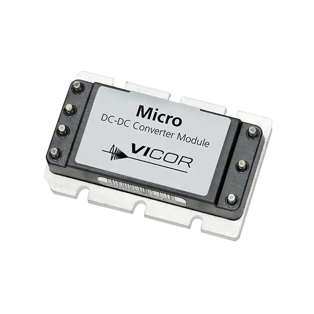


 工商网监
湘ICP备2023018690号
工商网监
湘ICP备2023018690号
