597D
Vishay Sprague
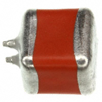
Solid Tantalum Chip Capacitors TANTAMOUNT®, Ultra-Low ESR, Conformal Coated, Maximum CV
FEATURES
• New case size offerings • Case profiles: E case (4 mm) and R case (3.6 mm) • Low profile case: V case (2 mm) • Terminations: Tin (2) standard • Extremely low ESR • Ripple current up to 4.1 A
Pb-free Available
RoHS*
COMPLIANT
PERFORMANCE CHARACTERISTICS
Operating Temperature: - 55 °C to + 85 °C (To + 125 °C with voltage derating)
Note: Refer to doc. 40088
Capacitance Range: 15 µF to 1500 µF Capacitance Tolerance: ± 10 %, ± 20 % standard Voltage Rating: 4 WVDC to 63 WVDC
ORDERING INFORMATION
597D TYPE 687 CAPACITANCE This is expressed in picofarads. The first two digits are the significant figures. The third is the number of zeros to follow. X0 CAPACITANCE TOLERANCE X0 = ± 20 % X9 = ± 10 % 6R3 DC VOLTAGE RATING AT + 85 °C This is expressed in volts. To complete the three-digit block, zeros precede the voltage rating. A decimal point is indicated by an “R” (6R3 = 6.3 V). E CASE CODE See Ratings and Case Codes Table 2 TERMINATION 2 = 100 % Tin 8 = Solder Plated (60/40) Special Order T REEL SIZE AND PACKAGING T =Tape and Reel 7" [500] Reel W = 13" [N/A] Reel
Note: Preferred Tolerance and reel sizes are in bold. We reserve the right to supply higher voltage ratings and tighter capacitance tolerance capacitors in the same case size Voltage substitutions will be marked with the higher voltage rating
DIMENSIONS in inches [millimeters]
Tantalum wire Nib identifies Anode (+) Terminal L
W
J
D B A
H
CASE CODE E F R V Z
L (MAX.) 0.287 ± 0.012 [7.3 ± 0.3] 0.287 ± 0.012 [7.3 ± 0.3] 0.287 ± 0.012 [7.3 ± 0.3] 0.287 ± 0.012 [7.3 ± 0.3] 0.287 ± 0.012 [7.3 ± 0.3]
W 0.173 ± 0.016 [4.4 ± 0.4] 0.238 ± 0.016 [6.0 ± 0.4] 0.238 + 0.016/- 0.024 [6.0 + 0.4/- 0.6] 0.173 ± 0.016 [4.4 ± 0.4] 0.238 ± 0.016 [6.0 ± 0.4]
H 0.157 ± 0.016 [4.0 ± 0.4] 0.187 ± 0.016 [4.7 ± 0.4] 0.142 ± 0.016 [3.6 ± 0.4] 0.079 [2.0] Max. 0.238 ± 0.016 [6.0 ± 0.4]
A 0.051 ± 0.012 [1.3 ± 0.3] 0.051 ± 0.012 [1.3 ± 0.3] 0.051 ± 0.012 [1.3 ± 0.3] 0.051 ± 0.012 [1.3 ± 0.3] 0.051 ± 0.012 [1.3 ± 0.3]
B 0.180 ± 0.025 [4.6 ± 0.6] 0.180 ± 0.025 [4.6 ± 0.6] 0.180 ± 0.025 [4.6 ± 0.6] 0.180 ± 0.025 [4.6 ± 0.6] 0.180 ± 0.025 [4.6 ± 0.6]
D (REF.) 0.253 [6.4] 0.243 [6.2] 0.243 [6.2] 0.253 [6.4] 0.243 [6.2]
J (MAX.) 0.004 [0.1] 0.004 [0.1] 0.004 [0.1] 0.004 [0.1] 0.004 [0.1]
Note: The anode termination (D less B) will be a minimum of 0.012" [0.3 mm] * Pb containing terminations are not RoHS compliant, exemptions may apply Document Number: 40047 Revision: 01-Aug-08 For technical questions, contact: tantalum@vishay.com www.vishay.com 107
�597D
Vishay Sprague
Solid Tantalum Chip Capacitors TANTAMOUNT®, Ultra-Low ESR, Conformal Coated, Maximum CV
6.3 V 10 V 16 V 20 V 25 V 35 V 50 V E/R R F Z* 63 V 75 V
RATINGS AND CASE CODE
µF 10 15 22 33 47 68 100 150 220 330 470 680 1000 1500 2200 4V
F*
R R F E V E E/R R V E E R E E R F* R F*
STANDARD RATINGS
CAPACITANCE (µF) 470 680 1000 1000 1500 330 470 680 1000 330 470 680 220 470 220 330 68 150 47 15 15 22 33 47 CASE CODE MAX. DCL MAX. DF MAX. ESR AT + 25 °C AT + 25 °C AT + 25 °C (µA) 120 Hz (%) 100 kHz (mΩ) 4 WVDC AT + 85 °C, SURGE = 5.2 V . . . 2.7 WVDC AT + 125 °C, SURGE = 3.4 V V 597D477X_004V__ 19 8 30 E 597D687X_004E__ 27 6 25 E 597D108X_004E__ 40 8 20 R 597D108X_004R__ 40 8 18 R 597D158X_004R__ 60 8 15 6.3 WVDC AT + 85 °C, SURGE = 8 V . . . 4 WVDC AT + 125 °C, SURGE = 5 V V 597D337X_6R3V__ 21 8 35 E 597D477X_6R3E__ 30 6 30 E 597D687X_6R3E__ 43 6 25 R 597D108X_6R3R__ 63 8 20 10 WVDC AT + 85 °C, SURGE = 13 V . . . 7 WVDC AT + 125 °C, SURGE = 8 V E 597D337X_010E__ 33 6 35 E 597D477X_010E__ 47 6 28 R 597D687X_010R__ 68 6 28 16 WVDC AT + 85 °C, SURGE = 20 V . . . 10 WVDC AT + 125 °C, SURGE = 12 V E 597D227X_016E__ 35 8 40 F 597D477X_016F__ * 75 14 100 20 WVDC AT + 85 °C, SURGE = 26 V . . . 13 WVDC AT + 125 °C, SURGE = 16 V R 597D227X_020R__ 44 8 80 F 597D337X_020F__* 66 10 100 25 WVDC AT + 85 °C, SURGE = 32 V . . . 17 WVDC AT + 125 °C, SURGE = 20 V 17 6 100 R 597D686X_025R__ 38 8 80 F 597D157X_025F__ 35 WVDC AT + 85 °C, SURGE = 46 V . . . 23 WVDC AT + 125 °C, SURGE = 28 V R 597D476X_035R__ 17 6 80 50 WVDC AT + 85 °C, SURGE = 65 V . . . 33 WVDC AT + 125 °C, SURGE = 38 V E 597D156X_050E__ 8 6 300 R 597D156X_050R__ 8 6 250 R 597D226X_050R__ 11 6 170 F 597D336X_050F__ 17 6 150 Z 597D476X_050Z__* 24 6 145 63 WVDC AT + 85 °C, SURGE = 81 V . . . 42 WVDC AT + 125 °C, SURGE = 54 V F 597D226X_063F__* 14 6 200 PART NUMBER MAX. RIPPLE 100 kHz IRMS (A) 2.2 2.9 3.3 3.7 4.1 2.0 2.7 2.9 3.5 2.5 2.8 2.9 2.3 1.4 1.8 1.4 1.6 1.8 1.8 0.8 1.0 0.8 0.8 1.1 0.9
22 Note: * Contact factory for availability www.vishay.com 108
For technical questions, contact: tantalum@vishay.com
Document Number: 40047 Revision: 01-Aug-08
�597D
Solid Tantalum Chip Capacitors TANTAMOUNT®, Ultra-Low ESR, Conformal Coated, Maximum CV
TYPICAL CURVES
T97 1500 µF - 4 V 'R' CASE SIZE ESR and Z vs. FREQUENCY 1 ESR
ESR and Z (Ω)
ESR and Z (Ω)
Vishay Sprague
T97 330 µF - 10 V 'E' CASE SIZE ESR and Z vs. FREQUENCY 1 ESR Z
Z
0.1
0.1
0.01 100 Hz 1 kHz 10 kHz FREQUENCY 100 kHz 1 MHz
0.01 100 Hz 1 kHz 10 kHz FREQUENCY (Hz ) 100 kHz 1 MHz
T97 1000 µF - 4 V 'E' CASE SIZE ESR and Z vs. FREQUENCY 1 ESR
T97 1000 µF - 6.3 V 'R' CASE SIZE ESR and Z vs. FREQUENCY 1
ESR
ESR and Z (Ω)
Z
ESR and Z (Ω)
Z
0.1
0.1
0.01 100 Hz 1 kHz 10 kHz FREQUENCY 100 kHz 1 MHz
0.01 100 Hz 1 kHz 10 kHz FREQUENCY 100 kHz 1 MHz
T97 330 µF - 6.3 V 'V' CASE SIZE ESR and Z vs. FREQUENCY 10 ESR
T97 470 µF - 4 V 'V' CASE SIZE ESR and Z vs. FREQUENCY 10 ESR
ESR and Z (Ω)
ESR and Z (Ω)
1
Z
1
Z
0.1
0.1
0.01 100 Hz 1 kHz 10 kHz FREQUENCY 100 kHz 1 MHz
0.01 100 Hz 1 kHz 10 kHz FREQUENCY 100 kHz 1 MHz
Document Number: 40047 Revision: 01-Aug-08
For technical questions, contact: tantalum@vishay.com
www.vishay.com 109
�Legal Disclaimer Notice
Vishay
Disclaimer
All product specifications and data are subject to change without notice. Vishay Intertechnology, Inc., its affiliates, agents, and employees, and all persons acting on its or their behalf (collectively, “Vishay”), disclaim any and all liability for any errors, inaccuracies or incompleteness contained herein or in any other disclosure relating to any product. Vishay disclaims any and all liability arising out of the use or application of any product described herein or of any information provided herein to the maximum extent permitted by law. The product specifications do not expand or otherwise modify Vishay’s terms and conditions of purchase, including but not limited to the warranty expressed therein, which apply to these products. No license, express or implied, by estoppel or otherwise, to any intellectual property rights is granted by this document or by any conduct of Vishay. The products shown herein are not designed for use in medical, life-saving, or life-sustaining applications unless otherwise expressly indicated. Customers using or selling Vishay products not expressly indicated for use in such applications do so entirely at their own risk and agree to fully indemnify Vishay for any damages arising or resulting from such use or sale. Please contact authorized Vishay personnel to obtain written terms and conditions regarding products designed for such applications. Product names and markings noted herein may be trademarks of their respective owners.
Document Number: 91000 Revision: 18-Jul-08
www.vishay.com 1
�


 工商网监
湘ICP备2023018690号
工商网监
湘ICP备2023018690号
