VLMG310./VLMH310./VLMO310./VLMP310./VLMY310.
Vishay Semiconductors
Standard SMD LED PLCC-2
FEATURES • • • • • • Lead (Pb)-free product-RoHS compliant SMD LEDs with exceptional brightness Luminous intensity categorized e3 Compatible with automatic placement equipment EIA and ICE standard package Compatible with infrared, vapor phase and wave solder processes according to CECC 00802 and J-STD-020B Available in 8 mm tape Low profile package Non-diffused lens: excellent for coupling to light pipes and backlighting Low power consumption Luminous intensity ratio in one packaging unit IVmax/IVmin ≤ 1.6 Preconditioning: acc. to JEDEC level 2a
94 8553
• • • • • •
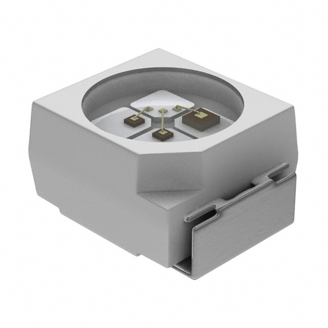
DESCRIPTION These devices have been designed to meet the increasing demand for surface mounting technology. The package of the VLM.310. is the PLCC-2. It consists of a lead frame which is embedded in a white thermoplast. The reflector inside this package is filled up with clear epoxy. PRODUCT GROUP AND PACKAGE DATA • Product group: LED • Package: SMD PLCC-2 • Product series: standard • Angle of half intensity: ± 60° PARTS TABLE
PART VLMH3100-GS08 VLMH3100-GS18 VLMH3101-GS08 VLMH3101-GS18 VLMH3102-GS08 VLMH3102-GS18 VLMO3100-GS08 VLMO3100-GS18 VLMO3101-GS08 VLMO3101-GS18 VLMY3100-GS08
APPLICATIONS • Automotive: backlighting in dashboards and switches • Telecommunication: indicator and backlighting in telephone and fax • Indicator and backlight for audio and video equipment • Indicator and backlight in office equipment • Flat backlight for LCDs, switches and symbols • General use
COLOR, LUMINOUS INTENSITY Red, IV > 2.8 mcd Red, IV > 2.8 mcd Red, IV = (4.5 to 11.2) mcd Red, IV = (4.5 to 11.2) mcd Red, IV = (7.1 to 18) mcd Red, IV = (7.1 to 18) mcd Soft orange, IV > 2.8 mcd Soft orange, IV > 2.8 mcd Soft orange, IV = (4.5 to 11.2) mcd Soft orange, IV = (4.5 to 11.2) mcd Yellow, IV > 2.8 mcd For technical support, please contact: LED@vishay.com
TECHNOLOGY GaAsP on GaP GaAsP on GaP GaAsP on GaP GaAsP on GaP GaAsP on GaP GaAsP on GaP GaAsP on GaP GaAsP on GaP GaAsP on GaP GaAsP on GaP GaAsP on GaP
Document Number 84789 Rev. 1.5, 16-May-08
www.vishay.com 1
�VLMG310./VLMH310./VLMO310./VLMP310./VLMY310.
Vishay Semiconductors
PARTS TABLE
PART VLMY3100-GS18 VLMY3101-GS08 VLMY3101-GS18 VLMY3102-GS08 VLMY3102-GS18 VLMG3100-GS08 VLMG3100-GS18 VLMG3102-GS08 VLMG3102-GS18 VLMG3105-GS08 VLMG3105-GS18 VLMP3100-GS08 VLMP3100-GS18 VLMP3101-GS08 VLMP3101-GS18 VLMP3107-GS08 VLMP3107-GS18 VLMP3102-GS08 VLMP3102-GS18 COLOR, LUMINOUS INTENSITY Yellow, IV > 2.8 mcd Yellow, IV = (4.5 to 11.2) mcd Yellow, IV = (4.5 to 11.2) mcd Yellow, IV = (7.1 to 18) mcd Yellow, IV = (7.1 to 18) mcd Green, IV > 4.5 mcd Green, IV > 4.5 mcd Green, IV = (11.2 to 18) mcd Green, IV = (11.2 to 18) mcd Green, IV = (7.1 to 18) mcd Green, IV = (7.1 to 18) mcd Pure green, IV > 1.12 mcd Pure green, IV > 1.12 mcd Pure green, IV = (1.8 to 4.5) mcd Pure green, IV = (1.8 to 4.5) mcd Pure green, IV = (2.8 to 5.6) mcd Pure green, IV = (2.8 to 5.6) mcd Pure green, IV = (2.8 to 7.1) mcd Pure green, IV = (2.8 to 7.1) mcd TECHNOLOGY GaAsP on GaP GaAsP on GaP GaAsP on GaP GaAsP on GaP GaAsP on GaP GaP on GaP GaP on GaP GaP on GaP GaP on GaP GaP on GaP GaP on GaP GaP on GaP GaP on GaP GaP on GaP GaP on GaP GaP on GaP GaP on GaP GaP on GaP GaP on GaP
ABSOLUTE MAXIMUM RATINGS 1) VLMG310. ,VLMH310. ,VLMO310. ,VLMP310. ,VLMY310.
PARAMETER Reverse voltage DC forward current Surge forward current Power dissipation Junction temperature Operating temperature range Storage temperature range Soldering temperature Thermal resistance junction/ ambient t≤5s mounted on PC board (pad size > 16 mm2) Tamb ≤ 60 °C tp ≤ 10 µs Tamb ≤ 60 °C TEST CONDITION SYMBOL VR IF IFSM PV Tj Tamb Tstg Tsd RthJA VALUE 6 30 0.5 100 100 - 40 to + 100 - 40 to + 100 260 400 UNIT V mA A mW °C °C °C °C K/W
Note: 1) Tamb = 25 °C, unless otherwise specified
OPTICAL AND ELECTRICAL CHARACTERISTICS 1) VLMH310., RED
PARAMETER Luminous intensity 2) Dominant wavelength Peak wavelength Angle of half intensity Forward voltage Reverse voltage Junction capacitance Note: 1) T amb = 25 °C, unless otherwise specified 2) In one packing unit IVmax/IVmin ≤ 1.6 www.vishay.com 2 For technical support, please contact: LED@vishay.com Document Number 84789 Rev. 1.5, 16-May-08 TEST CONDITION IF = 10 mA IF = 10 mA IF = 10 mA IF = 10 mA IF = 20 mA IR = 10 µA VR = 0, f = 1 MHz PART VLMH3100 VLMH3101 VLMH3102 SYMBOL IV IV IV λd λp ϕ VF VR Cj 6 MIN. 2.8 4.5 7.1 612 635 ± 60 2 15 15 2.8 TYP. 10 11.2 18 625 MAX. UNIT mcd mcd mcd nm nm deg V V pF
�VLMG310./VLMH310./VLMO310./VLMP310./VLMY310.
Vishay Semiconductors
OPTICAL AND ELECTRICAL CHARACTERISTICS 1) VLMO310., SOFT ORANGE
PARAMETER Luminous intensity 2) Dominant wavelength Peak wavelength Angle of half intensity Forward voltage Reverse voltage Junction capacitance Note: 1) Tamb = 25 °C, unless otherwise specified 2) In one packing unit I Vmax/IVmin ≤ 1.6 TEST CONDITION IF = 10 mA IF = 10 mA IF = 10 mA IF = 10 mA IF = 20 mA IR = 10 µA VR = 0, f = 1 MHz PART VLMO3100 VLMO3101 SYMBOL IV IV λd λp ϕ VF VR Cj 6 MIN. 2.8 4.5 598 605 ± 60 2 15 15 2.8 TYP. 8 11.2 611 MAX. UNIT mcd mcd nm nm deg V V pF
OPTICAL AND ELECTRICAL CHARACTERISTICS 1) VLMY310., YELLOW
PARAMETER Luminous intensity
2)
TEST CONDITION IF = 10 mA IF = 10 mA IF = 10 mA IF = 10 mA IF = 20 mA IR = 10 µA VR = 0, f = 1 MHz
PART VLMY3100 VLMY3101 VLMY3102
SYMBOL IV IV IV λd λp ϕ VF VR Cj
MIN. 2.8 4.5 7.1 581
TYP. 10
MAX. 11.2 18 594
UNIT mcd mcd mcd nm nm deg
Dominant wavelength Peak wavelength Angle of half intensity Forward voltage Reverse voltage Junction capacitance Note: Tamb = 25 °C, unless otherwise specified 2) In one packing unit I Vmax/IVmin ≤ 1.6
1)
585 ± 60 2.1 6 15 15 2.8
V V pF
OPTICAL AND ELECTRICAL CHARACTERISTICS 1) VLMG310., GREEN
PARAMETER Luminous intensity
2)
TEST CONDITION IF = 10 mA IF = 10 mA IF = 10 mA IF = 10 mA IF = 20 mA IR = 10 µA VR = 0, f = 1 MHz
PART VLMG3100 VLMG3102 VLMG3105
SYMBOL IV IV IV λd λp ϕ VF VR Cj
MIN. 4.5 11.2 7.1 562
TYP. 16
MAX. 18 18 575
UNIT mcd mcd mcd nm nm deg
Dominant wavelength Peak wavelength Angle of half intensity Forward voltage Reverse voltage Junction capacitance Note: Tamb = 25 °C, unless otherwise specified 2) In one packing unit IVmax/IVmin ≤ 1.6
1)
565 ± 60 2.2 6 15 15 2.8
V V pF
Document Number 84789 Rev. 1.5, 16-May-08
For technical support, please contact: LED@vishay.com
www.vishay.com 3
�VLMG310./VLMH310./VLMO310./VLMP310./VLMY310.
Vishay Semiconductors
OPTICAL AND ELECTRICAL CHARACTERISTICS 1) VLMP310., PURE GREEN
PARAMETER TEST CONDITION PART VLMP3100 Luminous intensity 2) IF = 10 mA VLMP3101 VLMP3102 VLMP3107 Dominant wavelength Peak wavelength Angle of half intensity Forward voltage Reverse voltage Junction capacitance Note: 1) Tamb = 25 °C, unless otherwise specified 2) In one packing unit IVmax/IVmin ≤ 1.6 IF = 10 mA IF = 10 mA IF = 10 mA IF = 20 mA IR = 10 µA VR = 0, f = 1 MHz SYMBOL IV IV IV IV λd λp ϕ VF VR Cj 6 MIN. 1.12 1.8 2.8 2.8 555 555 ± 60 2.1 15 15 2.8 TYP. 4 4.5 7.1 5.6 565 MAX. UNIT mcd mcd mcd mcd nm nm deg V V pF
COLOR CLASSIFICATION
YELLOW GROUP MIN. 0 1 2 3 4 5 6 7 8 581 583 585 587 589 591 584 586 588 590 592 594 564 566 568 570 572 567 569 571 573 575 598 600 602 604 606 608 606 608 601 603 605 607 609 611 609 611 MAX. MIN. GREEN MAX. SOFTORANGE MIN. MAX. PURE GREEN MIN. 555 558 560 562 MAX. 559 561 563 565 DOM. WAVELENGTH (nm) DOM. WAVELENGTH (nm)
LUMINOUS INTENSITY CLASSIFICATION
GROUP STANDARD F G H J K L M 2 1 2 1 2 1 2 1 2 1 2 1 2 LIGHT INTENSITY (mcd) OPTIONAL MIN. 1.40 1.80 2.24 2.80 3.55 4.50 5.60 7.10 9.00 11.20 14.00 18.00 22.40 MAX. 1.80 2.24 2.80 3.55 4.50 5.60 7.10 9.00 11.20 14.00 18.00 22.40 28.00
Note: Luminous intensity is tested at a current pulse duration of 25 ms and an accuracy of ± 11 %. The above Type Numbers represent the order groups which include only a few brightness groups. Only one group will be shipped on each reel (there will be no mixing of two groups on each reel). In order to ensure availability, single brightness groups will not be orderable. In a similar manner for colors where wavelength groups are measured and binned, single wavelength groups will be shipped on any one reel. In order to ensure availability, single wavelength groups will not be orderable.
www.vishay.com 4
For technical support, please contact: LED@vishay.com
Document Number 84789 Rev. 1.5, 16-May-08
�VLMG310./VLMH310./VLMO310./VLMP310./VLMY310.
Vishay Semiconductors
CROSSING TABLE
VISHAY VLMH3100 VLMH3101 VLMH3102 VLMO3100 VLMO3101 VLMY3100 VLMY3101 VLMY3102 VLMG3100 VLMG3102 VLMG3105 VLMP3100 VLMP3101 VLMP3102 VLMP3107 OSRAM LOT670J1L2 LOT670J1K2 LYT670J1L2 LYT670J1K2 LYT670K1L2 LGT670K1M2 LGT670L1L2 LGT671K1L2 LPT670F2J2 LPT670G1H2 LPT670H1J2 LPT670H1J1 STANLEY VYBG1104B VYBG1101W -
TYPICAL CHARACTERISTICS Tamb = 25 °C, unless otherwise specified
0° 10° 20° 30°
IV rel - Relative Luminous Intensity
60
IF - Forward Current (mA)
50 40 30 20 10 0 0 20 40 60 80 100
40° 1.0 0.9 0.8 0.7 50° 60° 70° 80° 0.6 0.4 0.2 0
95 10319
95 10905
Tamb - Ambient Temperature (°C)
Figure 1. Maximum Permissible Forward Current vs. Ambient Temperature
Figure 3. Relative Luminous Intensity vs. Angular Displacement
10000
t p /T = 0.005 Tamb < 60 °C 0.01 0.02 0.05
100 red IF - Forward Current (mA)
I F - Forward Current (mA)
1000
10
100
0.2 0.5 DC
1
10
0.1
1 0.01
95 9985
0.1 0.1 1 10 100 0
95 9989_1
1
2
3
4
5
t p - Pulse Length (ms)
VF - Forward Voltage (V)
Figure 2. Permissible Pulse Forward Current vs. Pulse Duration
Figure 4. Forward Current vs. Forward Voltage
Document Number 84789 Rev. 1.5, 16-May-08
For technical support, please contact: LED@vishay.com
www.vishay.com 5
ϕ - Angular Displacement
�VLMG310./VLMH310./VLMO310./VLMP310./VLMY310.
Vishay Semiconductors
2.0 IV rel - Relative Luminous Intensity red
1.2 red 1.0
I rel - Relative Intensity
1.6
0.8 0.6 0.4 0.2 0 590
1.2
0.8 0.4 0 0 20 40 60 80 100
610
630
650
670
690
95 9993_1
Tamb - Ambient Temperature (°C)
95 10040_1
λ - Wavelength (nm)
Figure 5. Relative Luminous Intensity vs. Ambient Temperature
Figure 8. Relative Intensity vs. Wavelength
2.4
100
red
soft orange I F - Forward Current (mA)
Ispec - Specific Luminous Intensity
2.0 1.6 1.2 0.8 0.4 0 10 20 0.5 50 0.2 100 0.1 200 0.05 500 I F (mA) 0.02 tp /T
10
1
0.1 0
95 9990
1
2
3
4
5
95 10321_1
1
V F - Forward Voltage (V)
Figure 6. Spec. Luminous Intensity vs. Forw. Current/Duty Cycle
Figure 9. Forward Current vs. Forward Voltage
10 IV rel - Relative Luminous Intensity IV rel - Relative Luminous Intensity red
2.0 soft orange 1.6
1
1.2
0.1
0.8 0.4 0
0.01 1
95 9995_1
10 IF - Forward Current (mA)
100
95 9994
0
20
40
60
80
100
Tamb - Ambient Temperature (°C)
Figure 7. Relative Luminous Intensity vs. Forward Current
Figure 10. Relative Luminous Intensity vs. Ambient Temperature
www.vishay.com 6
For technical support, please contact: LED@vishay.com
Document Number 84789 Rev. 1.5, 16-May-08
�VLMG310./VLMH310./VLMO310./VLMP310./VLMY310.
Vishay Semiconductors
2.4 Ispec - Specific Luminous Intensity soft orange 2.0 1.6 1.2 0.8 0.4 0 10
95 10259
100 yellow
- Forward Current (mA) I
F
10
1
0.1
20 0.5
50 0.2
100 0.1
200 0.05
500 I F (mA) 0.02 tp /T
95 9987
0
1
2
3
4
5
1
V F - Forward Voltage (V)
Figure 11. Specific Luminous Intensity vs. Forw. Current/Duty Cycle
Figure 14. Forward Current vs. Forward Voltage
I v rel - Relative Luminous Intensity
10
I v rel - Relative Luminous Intensity
2.0
soft orange
yellow 1.6
1
1.2
0.8
0.1
0.4
0.01 1
95 9997
0
10 I F - Forward Current (mA)
100
95 9992
0
20
40
60
80
100
T amb - Ambient Temperature (°C)
Figure 12. Relative Luminous Intensity vs. Forward Current
Figure 15. Relative Luminous Intensity vs. Ambient Temperature
1.2 Ispec - Specific Luminous Intensity soft orange 1.0
Irel - Relative Intensity
2.4 yellow 2.0 1.6 1.2 0.8 0.4 0 590 610 630 650 670
95 10260
0.8 0.6 0.4 0.2 0 570
95 10324
λ - Wavelength (nm)
10 1
20 0.5
50 0.2
100 0.1
200 0.05
500 I F (mA) 0.02 tp /T
Figure 13. Relative Intensity vs. Wavelength
Figure 16. Specific Luminous Intensity vs. Forw. Current/Duty Cycle
Document Number 84789 Rev. 1.5, 16-May-08
For technical support, please contact: LED@vishay.com
www.vishay.com 7
�VLMG310./VLMH310./VLMO310./VLMP310./VLMY310.
Vishay Semiconductors
10
I v rel - Relative Luminous Intensity
2.0
I v rel - Relative Luminous Intensity
yellow
green 1.6
1
1.2
0.8
0.1
0.4
0.01 1
95 9999
0
10 I F - Forward Current (mA)
100
0
95 10320
20
40
60
80
100
T amb - Ambient Temperature (°C)
Figure 17. Relative Luminous Intensity vs. Forward Current
Figure 20. Relative Luminous Intensity vs. Ambient Temperature
1.2 1.0
Irel - Relative Intensity
2.4
Ispec - Specific Luminous Intensity
yellow
green 2.0 1.6 1.2 0.8 0.4 0
0.8 0.6 0.4 0.2 0 550
570
590
610
630
650
95 10263
10 1
20 0.5
50 0.2
100 0.1
200 0.05
500 0.02
IF (mA)
t p /T
95 10039
λ - Wavelength (nm)
Figure 18. Relative Intensity vs. Wavelength
Figure 21. Specific Luminous Intensity vs. Forward Current
green
I v rel - Relative Luminous Intensity
100
10 green
I F - Forward Current (mA)
10
1
1
0.1
0.1 0
95 9986
0.01
1
2
3
4
5
95 9996
1
10
100
V F - Forward Voltage (V)
I F - Forward Current (mA)
Figure 19. Forward Current vs. Forward Voltage
Figure 22. Relative Luminous Intensity vs. Forward Current
www.vishay.com 8
For technical support, please contact: LED@vishay.com
Document Number 84789 Rev. 1.5, 16-May-08
�VLMG310./VLMH310./VLMO310./VLMP310./VLMY310.
Vishay Semiconductors
1.2 green
2.4
I Spec - Specific Luminous Flux
pure green
2.0 1.6 1.2 0.8 0.4 0
1.0
Irel - Relative Intensity
0.8 0.6 0.4 0.2 0 520
540
560
580
600
620
10
95 10261
100
1000
95 10038
λ - Wavelength (nm)
I F - Forward Current (mA)
Figure 23. Relative Intensity vs. Wavelength
Figure 26. Specific Luminous Intensity vs. Forward Current
100
10 I Vrel - Relative Luminous Intensity pure green
pure green
I F - Forward Current (mA)
10
1
1
0.1
0.1 0
95 9988
0.01
1 2 3 4 5
95 9998
1
V F - Forward Voltage (V)
10 I F - Forward Current (mA)
100
Figure 24. Forward Current vs. Forward Voltage
Figure 27. Relative Luminous Intensity vs. Forward Current
2.0
1.2
pure green Irel - Relative Intensity
I Vrel - Relative Luminous Intensity
pure green 1.0
0.8 0.6 0.4 0.2 0 500
95 10325
1.6
1.2
0.8
0.4
0 0
95 9991
20
40
60
80
100
520
540
560
580
600
Tamb - Ambient Temperature (°C)
λ - Wavelength (nm)
Figure 25. Relative Luminous Intensity vs. Ambient Temperature
Figure 28. Relative Intensity vs. Wavelength
Document Number 84789 Rev. 1.5, 16-May-08
For technical support, please contact: LED@vishay.com
www.vishay.com 9
�VLMG310./VLMH310./VLMO310./VLMP310./VLMY310.
Vishay Semiconductors
PACKAGE DIMENSIONS in millimeters
Mounting Pad Layout 1.2 area covered with solder resist
2.6 (2.8)
4 1.6 (1.9)
20541
METHOD OF TAPING/POLARITY AND TAPE AND REEL SMD LED (VLM3-SERIES) Vishay’s LEDs in SMD packages are available in an antistatic 8 mm blister tape (in accordance with DIN IEC 40 (CO) 564) for automatic component insertion. The blister tape is a plastic strip with impressed component cavities, covered by a top tape. TAPING OF VLM.3..
4
3.5 3.1
2.2 2.0
5.75 5.25 3.6 3.4
1.85 1.65
4.0 3.6 8.3 7.7
Adhesive tape
Blister tape
1.6 1.4
4.1 3.9
2.05 1.95
4.1 3.9
0.25
94 8668
Figure 29. Tape Dimensions in mm for PLCC-2
Component cavity
94 8670
www.vishay.com 10
For technical support, please contact: LED@vishay.com
Document Number 84789 Rev. 1.5, 16-May-08
�VLMG310./VLMH310./VLMO310./VLMP310./VLMY310.
Vishay Semiconductors
REEL PACKAGE DIMENSION IN MM FOR SMD LEDS, TAPE OPTION GS08 (= 1500 PCS.)
120° 10.0 9.0
SOLDERING PROFILE
IR Reflow Soldering Profile for Lead (Pb)-free Soldering
Preconditioning acc. to JEDEC Level 2a
300 250 Temperature (°C) 200 max. 30 s 150 max. 120 s 100 50 max. ramp up 3 °C/s max. ramp down 6 °C/s max. 100 s 255 °C 240 °C 217 °C max. 260 °C 245 °C
4.5 3.5 2.5 1.5
13.00 12.75 63.5 60.5
Identification Label: Vishay Type Group Tape Code Production Code Quantity
180 178
14.4 max.
94 8665
0 0
19885
50
100
150 Time (s)
200
250
300
Figure 30. Reel Dimensions - GS08
max. 2 cycles allowed
Figure 32. Vishay Lead (Pb)-free Reflow Soldering Profile (acc. to J-STD-020B)
REEL PACKAGE DIMENSION IN MM FOR SMD LEDS, TAPE OPTION GS18 (= 8000 PCS.) PREFERRED
10.4 8.4
TTW Soldering 300 250 5s 235 °C to 260 °C first wave ca. 200 K/s 100 °C to 130 °C 100 50 0 0 50
(acc. to CECC00802)
948626-1
lead temperature second wave ca. 2 K/s full line: typical dotted line: process limits
120°
Temperature (°C)
62.5 60.0
200 150
4.5 3.5 2.5 1.5
13.00 12.75
Identification Label: Vishay Type Group Tape Code Production Code Quantity
2 K/s forced cooling 100 Time (s) 150
ca. 5 K/s
200
250
321 329
14.4 max.
18857
Figure 33. Double Wave Soldering of Opto Devices (all Packages)
Figure 31. Reel Dimensions - GS18
Document Number 84789 Rev. 1.5, 16-May-08
For technical support, please contact: LED@vishay.com
www.vishay.com 11
�VLMG310./VLMH310./VLMO310./VLMP310./VLMY310.
Vishay Semiconductors
BAR CODE PRODUCT LABEL EXAMPLE: RECOMMENDED METHOD OF STORAGE Dry box storage is recommended as soon as the aluminum bag has been opened to prevent moisture absorption. The following conditions should be observed, if dry boxes are not available: • Storage temperature 10 °C to 30 °C • Storage humidity ≤ 60 % RH max. After more than 672 h under these conditions moisture content will be too high for reflow soldering. In case of moisture absorption, the devices will recover to the former condition by drying under the following condition: 192 h at 40 °C + 5 °C/- 0 °C and < 5 % RH (dry air/nitrogen) or 96 h at 60 °C + 5 °C and < 5 % RH for all device containers or 24 h at 100 °C + 5 °C not suitable for reel or tubes. An EIA JEDEC standard JESD22-A112 level 2a label is included on all dry bags.
LEVEL This bag contains MOISTURE –SENSITIVE DEVICES
106
A H VISHAY
37
B
C
D
E
F
G
19788
A) Type of component B) Manufacturing plant C) SEL - selection code (bin): e.g.: K1 = code for luminous intensity group 4 = code for color group D) Date code year/week E) Day code (e.g. 2: Tuesday) F) Batch no. G) Total quantity H) Company code DRY PACKING The reel is packed in an anti-humidity bag to protect the devices from absorbing moisture during transportation and storage.
CAUTION
2a
1. Shelf life in sealed bag 12 months at