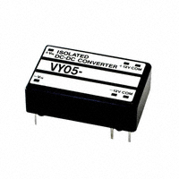
Correspond to Analog Ciruits, Ultra Low Noise 8mVp-p Small Size, Long-Life, Isolated Type DC-DC Converter
1.5 Watt VY-L Series
VY-L series is a long-life, ultra low noise and isolated type DC-DC converter which is most suitable for analog circuits and analog-digital circuits. It has achieved low conducted emission and low radiated emission with the improved TCT circuit. The output noise is ultra low noise of 8mVp-p and has the ability to become the industry leader.
- Ultra Low Noise, 8mVp-p typ. - 24pin DIP IC Size, 5-Side Metallic Shield Case - Wide Operating Temp. Range -25°C to +71°C - Possible to start-up from -30°C (No guarantee) - No Electrolytic Capacitor, No Tantalum Capacitor - MTBF 1,000,000Hrs , All aging - High Reliability with the Latest SMD Structure - Over-Heat Protection - Over-Current protection - Isolation Capacitance 100pF max. - Isolated Type: DC500V - Most Suitable for Analog and Digital Circuits -High Reliability, Long-Life, High Performance - New TCT Circuits (Patented) Table 1 Rating lnput Voltage VY-L(1.5W) Series VY05-05S30L VY05-09S16L VY05-12S12L VY05-15S10L VY05-05W08L VY05-12W06L VY05-15W05L Vdc 5 5 5 5 5 5 5 Input Voltage Range Vdc-Vdc 4.75-6 4.75-6 4.75-6 4.75-6 4.75-6 4.75-6 4.75-6 Output Voltage Vdc 5 9 12 15 ±5 ±12 ±15 Output I Current mA 0-300 0-160 0-120 0-100 ±0-80 ±0-65 ±0-53 %(max.) 0.3 0.3 0.3 0.3 0.5 0.5 0.5 %(max.) 0.3 0.3 0.3 0.3 0.5 0.5 0.5 mVpp(typ.) 10 10 10 10 8 8 8 %(typ.) 60 60 60 60 45 60 60 Line Reg Load Reg Noise Efficiency
Model
* This model is compatible with the old VY series to be used for substitutions. Table 2 Input Voltage/ Range 5V±0.25V (Refer to the derating curve when input is 5.25-6.0V) Output Voltage Refer to Table 1 Line Regulation Refer to Table 1 (For the input voltage range of 5V±5%, at rating load) Load Regulation Refer to Table 1 (For the load regulation of 0-100%, at rating input voltage) Temperature Coefficient ±0.02%/°C typ. (When operating temperature changes between -20°C to +70°C ) Short Term Drift 50mV/ 8H max. (Except initial drift) Ripple & Noise (1)VY-SL: 10mVp-p typ. 15mVp-p max. (2)VY-WL: 8mVp-p typ. 15mVp-p max. (20MHz bandwidth) Efficiency 60% typ. (Rating input/ output, room temperature, refer to Table 1) Over-Current Protection Operates at 105% or more rating load current, auto recovery type. Over-Voltage Protection None Over-Heat Protection Built-in in the regulator part EMI Line Filter Built-in LC type line filter MTBF 1,000,000Hr (EIAJ RCR-9102) Isolation Voltage Between primary and secondary DC500V: for 1min., between case and input/ output DC500V: for 1min. Isolation Resistance Between primary and secondary DC500V: 10M ohm or more, between case and input/output DC500V: 10M ohm or more. Isolation Capacitance Between primary and secondary capacitance: 100pF max. Operating Temperature Range -25°C to +71°C (Temperature derating required from +50°C) Storage Temperature Range -30°C to +85°C Humidity Range 95%R. H. max. Cooling Condition Natural convection 5-10Hz All amplitude 10mm (1hour in each of 3 directional axes), Vibration 10-55Hz acceleration 2G (1 hour in each of 3 directional axes) Shock Acceleration 20G (3 times in each of 3 directional axes), Shocking time 11±5ms Weight 14g typ. Outline W=20.42 L=32.6 H=10.3 (mm) (For detail dimensions refer to the outline.) *The above specification is provided with rating value, unless otherwise specified.
Kaga Electronics/Volgen DC-DC CONVERTERS
www.volgen.com
�1.5 Watt VY-L Series
VY-SL Series
N.P
VY-WL Series
N.P
10.3
10.3
9.8
9.8
5typ
0.5
0.5
2.54
2.54
Φ0.6
2.54
2.54
Φ0.6
20.42
20.42
15.24
15.24
1
10
12
1
10
12
24
15
13
24
15
13
(2.33)
22.86 32.6
5.08
(2.33)
(2.33)
22.86 32.6
5.08 (2.33)
Figure 1 - Dimensions: mm, Weight: 14g typ. - 5-Side Metallic Shield Case, black plating (with a standoff)
Figure 2
- Pin side is not shielded. It is recommended to set a pattern wider than the converter's bottom area right under the converter.
VY-SL Series (5V, 9V, 12V, 15V)
VY-WL Series (±12V, ±15V)
- Recommended capacitor C1=22µF -33µF (Electrolytic or multilayer ceramic capacitor) C2=0.47-10µF (Electrolytic or multilayer ceramic capacitor) Figure 3 - High frequency and low impedance capacitors are recommended.
- Recommended capacitor C1=22µF -33µF (Electrolytic or multilayer ceramic capacitor) C2, C3=0.47-10µF (Electrolytic or multilayer ceramic capacitor) Figure 4
- Basically, external capacitors are not required, but noise can be lowered by reducing power line impedance and load line impedance. - Noise can also be lowered by designing the pattern with short lead and not to make a loop.
VY-SL Series
+Vin 24
L1 T1 TR1 CT1 C1 C2 C3 IC1 C4 C5 D3 C6 D1 L2 D4
VY-WL Series
+Vout 15 13
C1 C2
+Vin 24
L1 TR1 C3 CT1
T1
D1,2
L2 IC1
D5
C4
C6
D6
C8
NEW NEW TCT TCT
TR2 R1 D2
NEW TCT TCT
R1 C5 C7 IC2 D3,4 L3 D8 D7 C9 TR2
12 1 -Vin 10 -Vout
1 -Vin
Figure 5
Figure 6
2
Kaga Electronics/Volgen DC-DC CONVERTERS
BDD20050408-021212
5typ
+Vout 15 Common 13 12 10 -Vout
�
很抱歉,暂时无法提供与“VY05-12S12L”相匹配的价格&库存,您可以联系我们找货
免费人工找货