Data sheet
OMNIMATE Signal - series LMF
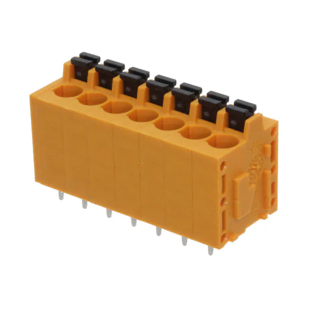
LMF 5.00/07/180 3.5SN OR BX
Weidmüller Interface GmbH & Co. KG
Klingenbergstraße 16
D-32758 Detmold
Germany
Fon: +49 5231 14-0
Fax: +49 5231 14-292083
www.weidmueller.com
Product image
Similar to illustration
The new LMF allows us to meet the current market
requirements for a PCB terminal with PUSH IN connection
system for wire cross-sections up to 2.5 mm2
• PUSH IN connection system
• LMF with pusher for opening the terminal point
• LMFS without pusher, the terminal point is opened with
a screwdriver
• Integrated test point
• 90° and 180° wire outlet direction
General ordering data
Type
Order No.
Version
GTIN (EAN)
Qty.
Product data
Packaging
LMF 5.00/07/180 3.5SN OR BX
1330230000
PCB terminal, 5.00 mm, No. of poles: 7, 180°,
Solder pin length (l): 3.5 mm, tinned, Orange,
PUSH IN, Clamping range, max. : 2.5 mm², Box
4050118133950
40 pc(s).
IEC: 400 V / 24 A / 0.2 - 2.5 mm²
UL: 300 V / 20 A / AWG 24 - AWG 12
Box
Creation date December 11, 2018 9:08:23 PM CET
Catalogue status 07.12.2018 / We reserve the right to make technical changes.
1
�
Data sheet
OMNIMATE Signal - series LMF
LMF 5.00/07/180 3.5SN OR BX
Weidmüller Interface GmbH & Co. KG
Klingenbergstraße 16
D-32758 Detmold
Germany
Fon: +49 5231 14-0
Fax: +49 5231 14-292083
www.weidmueller.com
Technical data
Dimensions and weights
Width
Height
Height of lowest version
Depth (inches)
37.7 mm
22.7 mm
19.2 mm
0.583 inch
Width (inches)
Height (inches)
Depth
Net weight
Wire connection method
Conductor outlet direction
Pitch in inches (P)
Fitted by customer
Solder pin length (l)
Solder eyelet hole diameter (D)
Number of solder pins per pole
Screwdriver blade standard
L1 in mm
Touch-safe protection acc. to DIN VDE
0470
Colour
CTI
UL 94 flammability rating
1.484 inch
0.894 inch
14.8 mm
12.5 g
System parameters
Product family
OMNIMATE Signal - series
LMF
Mounting onto the PCB
THT solder connection
Pitch in mm (P)
5 mm
No. of poles
7
Max. adjacent poles per row
24
Solder pin dimensions
d = 0.8 mm
Solder eyelet hole diameter tolerance (D)+ 0,1 mm
Screwdriver blade
0.6 x 3.5
Stripping length
10 mm
L1 in inches
1.181 inch
Touch-safe protection acc. to DIN VDE
57 106
Safe from finger touch
PUSH IN
180°
0.197 inch
No
3.5 mm
1.1 mm
2
DIN 5264
30 mm
IP 20
Material data
Insulating material
Colour chart (similar)
Insulation resistance
Contact material
Coating
Layer structure of solder connection
Storage temperature, max.
Operating temperature, min.
Temperature range, installation, min.
Wemid (PA)
RAL 2000
≥ 108 Ω
CuSn
4-6 μm SN
4-6 µm Sn matt
55 °C
-50 °C
-25 °C
Contact surface
Tinning type
Storage temperature, min.
Max. relative humidity during storage
Operating temperature, max.
Temperature range, installation, max.
Orange
≥ 600
V-0
tinned
matt
-25 °C
80 %
120 °C
120 °C
Conductors suitable for connection
Clamping range, min.
0.12 mm²
Wire connection cross section AWG,
min.
AWG 24
Solid, min. H05(07) V-U
0.2 mm²
Flexible, min. H05(07) V-K
0.2 mm²
w. plastic collar ferrule, DIN 46228 pt 4,
min.
0.25 mm²
w. wire end ferrule, DIN 46228 pt 1, min
0.25 mm²
Plug gauge in accordance with EN
60999 a x b; ø
2.4 mm x 1.5 mm
Clamping range, max.
2.5 mm²
Wire connection cross section AWG,
max.
AWG 12
Solid, max. H05(07) V-U
2.5 mm²
Flexible, max. H05(07) V-K
2.5 mm²
w. plastic collar ferrule, DIN 46228 pt 4,
max.
2.5 mm²
w. wire end ferrule, DIN 46228 pt 1,
max.
2.5 mm²
Creation date December 11, 2018 9:08:23 PM CET
Catalogue status 07.12.2018 / We reserve the right to make technical changes.
2
�
Data sheet
OMNIMATE Signal - series LMF
LMF 5.00/07/180 3.5SN OR BX
Weidmüller Interface GmbH & Co. KG
Klingenbergstraße 16
D-32758 Detmold
Germany
Fon: +49 5231 14-0
Fax: +49 5231 14-292083
www.weidmueller.com
Technical data
Rated data acc. to IEC
tested acc. to standard
Rated current, max. no. of poles
(Tu=20°C)
Rated current, max. no. of poles
(Tu=40°C)
Rated voltage for surge voltage class /
pollution degree III/2
Rated impulse voltage for surge voltage
class/ pollution degree II/2
Rated impulse voltage for surge voltage
class/ contamination degree III/3
Rated current, min. no. of poles
(Tu=20°C)
Rated current, min. no. of poles
(Tu=40°C)
Rated voltage for surge voltage class /
pollution degree II/2
Rated voltage for surge voltage class /
pollution degree III/3
Rated impulse voltage for surge voltage
class/ pollution degree III/2
Short-time withstand current resistance
Certificate No. (CSA)
Rated voltage (use group D)
Rated current (use group D)
Wire cross-section, AWG, max.
Certificate No. (cURus)
300 V
20 A
AWG 24
Specifications are
maximum values, details see approval certificate.
Rated voltage (use group D)
Rated current (use group D)
Wire cross-section, AWG, max.
Box
110 mm
VPE length
VPE height
40 mm
225 mm
EC001284
EC002643
27-26-11-01
27-44-04-01
27-44-04-01
ETIM 4.0
ETIM 6.0
eClass 7.1
eClass 9.0
EC002643
EC002643
27-44-04-01
27-44-04-01
IEC 60664-1, IEC 61984
24 A
24 A
320 V
4 kV
4 kV
24 A
24 A
400 V
250 V
4 kV
3 x 1s with 120 A
Rated data acc. to CSA
Institute (CSA)
Rated voltage (Use group B)
Rated current (use group B)
Wire cross-section, AWG, min.
Reference to approval values
300 V
20 A
AWG 24
Specifications are
maximum values, details see approval certificate.
20039-1815154
300 V
10 A
AWG 12
Rated data acc. to UL 1059
Institute (cURus)
Rated voltage (use group B)
Rated current (use group B)
Wire cross-section, AWG, min.
Reference to approval values
E60693
300 V
10 A
AWG 12
Packaging
Packaging
VPE width
Classifications
ETIM 3.0
ETIM 5.0
eClass 6.2
eClass 8.1
eClass 9.1
Creation date December 11, 2018 9:08:23 PM CET
Catalogue status 07.12.2018 / We reserve the right to make technical changes.
3
�
Data sheet
OMNIMATE Signal - series LMF
LMF 5.00/07/180 3.5SN OR BX
Technical data
Weidmüller Interface GmbH & Co. KG
Klingenbergstraße 16
D-32758 Detmold
Germany
Fon: +49 5231 14-0
Fax: +49 5231 14-292083
www.weidmueller.com
Notes
Notes
• Additional colours on request
• Rated current related to rated cross-section & min. No. of poles.
• Wire end ferrule without plastic collar to DIN 46228/1
• Wire end ferrule with plastic collar to DIN 46228/4
• P on drawing = pitch
• Rated data refer only to the component itself. Clearance and creepage distances to other components are to
be designed in accordance with the relevant application standards.
IPC conformity
• The test point can only be used as potential-pickup point.
Conformity: The products are developed, manufactured and delivered according international recognized
standards and norms and comply with the assured properties in the data sheet resp. fulfill decorative properties
in accordance with IPC-A-610 "Class 2". Further claims on the products can be evaluated on request.
Approvals
Approvals
ROHS
Conform
Downloads
Approval/Certificate/Document of
Conformity
Brochure/Catalogue
Engineering Data
Declaration of the Manufacturer
FL DRIVES EN
FL ANALO.SIGN.CONV. EN
MB DEVICE MANUF. EN
FL DRIVES DE
CAT 2 PORTFOLIOGUIDE EN
FL BUILDING SAFETY EN
FL APPL LED LIGHTING EN
FL INDUSTR.CONTROLS EN
FL MACHINE SAFETY EN
FL HEATING ELECTR EN
FL APPL_INVERTER EN
FL_BASE_STATION_EN
FL ELEVATOR EN
FL POWER SUPPLY EN
FL 72H SAMPLE SER EN
PO OMNIMATE EN
EPLAN, WSCAD
Creation date December 11, 2018 9:08:23 PM CET
Catalogue status 07.12.2018 / We reserve the right to make technical changes.
4
�
Data sheet
OMNIMATE Signal - series LMF
LMF 5.00/07/180 3.5SN OR BX
Weidmüller Interface GmbH & Co. KG
Klingenbergstraße 16
D-32758 Detmold
Germany
Fon: +49 5231 14-0
Fax: +49 5231 14-292083
www.weidmueller.com
Drawings
Dimensional drawing
Graph
Graph
Creation date December 11, 2018 9:08:23 PM CET
Catalogue status 07.12.2018 / We reserve the right to make technical changes.
5
�Wave Solder Profile
Recommended wave solderding profiles
Weidmüller Interface GmbH & Co. KG
Klingenbergstraße 16
D-32758 Detmold
Germany
Fon: +49 5231 14-0
Fax: +49 5231 14-292083
www.weidmueller.com
Single Wave:
260
Contact time appr. 3 sec.
260 °C
255 °C
250 °C
240
220
200
Temperature [°C]
180
160
140
appr. 150 °C
Preheating
120
100
Cooling rate < 6 °K/s
80
60
Typical process
Prozess limits
Temperature on board
40
Heating rate < 3 °K/s
20
0
0
20
40
60
80
100
120
time [s]
140
160
180
200
220
240
Double Wave:
255 °C
Total contact time max. 10 sec.
260
240
260 °C
250 °C
220
200
Temperature [°C]
180
160
140
appr. 150°C
Preheating
120
100
Cooling rate < 6 °K/s
80
60
Typical process
Process limits
Temperature on board
40
Heating rate < 3 °K/s
20
0
0
20
40
60
Wave soldering profiles
80
100
120
time [s]
140
160
180
200
220
240
Wired connection elements should be processed in accordance with the DIN EN 61760-1 standard. We have included
two recommendations for practical wave soldering profiles, with which Weidmüller PCB terminals and connectors are
qualified.
When choosing a suitable profile for your application, the following factors also need to be considered:
- PCB thickness
- Proportion of Cu in the layers
- Single/double-sided assembly
- Product range
- Heating and cooling rates
The single and double wave profiles each indicate the recommended operating range, including the maximum
soldering temperature of 260°C. In practice, the maximum soldering temperature is quite often well below the above
maximum profile.
We reserve the right to make technical changes.
�